CN103857504A - Apparatus for preparing plastic materials - Google Patents
Apparatus for preparing plastic materials Download PDFInfo
- Publication number
- CN103857504A CN103857504A CN201280050421.4A CN201280050421A CN103857504A CN 103857504 A CN103857504 A CN 103857504A CN 201280050421 A CN201280050421 A CN 201280050421A CN 103857504 A CN103857504 A CN 103857504A
- Authority
- CN
- China
- Prior art keywords
- screw
- container
- housing
- conveyor
- opening
- Prior art date
- Legal status (The legal status is an assumption and is not a legal conclusion. Google has not performed a legal analysis and makes no representation as to the accuracy of the status listed.)
- Granted
Links
Images


Classifications
-
- B—PERFORMING OPERATIONS; TRANSPORTING
- B29—WORKING OF PLASTICS; WORKING OF SUBSTANCES IN A PLASTIC STATE IN GENERAL
- B29C—SHAPING OR JOINING OF PLASTICS; SHAPING OF MATERIAL IN A PLASTIC STATE, NOT OTHERWISE PROVIDED FOR; AFTER-TREATMENT OF THE SHAPED PRODUCTS, e.g. REPAIRING
- B29C48/00—Extrusion moulding, i.e. expressing the moulding material through a die or nozzle which imparts the desired form; Apparatus therefor
- B29C48/25—Component parts, details or accessories; Auxiliary operations
- B29C48/285—Feeding the extrusion material to the extruder
- B29C48/288—Feeding the extrusion material to the extruder in solid form, e.g. powder or granules
-
- B—PERFORMING OPERATIONS; TRANSPORTING
- B29—WORKING OF PLASTICS; WORKING OF SUBSTANCES IN A PLASTIC STATE IN GENERAL
- B29B—PREPARATION OR PRETREATMENT OF THE MATERIAL TO BE SHAPED; MAKING GRANULES OR PREFORMS; RECOVERY OF PLASTICS OR OTHER CONSTITUENTS OF WASTE MATERIAL CONTAINING PLASTICS
- B29B17/00—Recovery of plastics or other constituents of waste material containing plastics
- B29B17/04—Disintegrating plastics, e.g. by milling
- B29B17/0412—Disintegrating plastics, e.g. by milling to large particles, e.g. beads, granules, flakes, slices
-
- B—PERFORMING OPERATIONS; TRANSPORTING
- B01—PHYSICAL OR CHEMICAL PROCESSES OR APPARATUS IN GENERAL
- B01F—MIXING, e.g. DISSOLVING, EMULSIFYING OR DISPERSING
- B01F35/00—Accessories for mixers; Auxiliary operations or auxiliary devices; Parts or details of general application
- B01F35/71—Feed mechanisms
-
- B—PERFORMING OPERATIONS; TRANSPORTING
- B01—PHYSICAL OR CHEMICAL PROCESSES OR APPARATUS IN GENERAL
- B01F—MIXING, e.g. DISSOLVING, EMULSIFYING OR DISPERSING
- B01F35/00—Accessories for mixers; Auxiliary operations or auxiliary devices; Parts or details of general application
- B01F35/75—Discharge mechanisms
- B01F35/754—Discharge mechanisms characterised by the means for discharging the components from the mixer
- B01F35/75455—Discharge mechanisms characterised by the means for discharging the components from the mixer using a rotary discharge means, e.g. a screw beneath the receptacle
- B01F35/754551—Discharge mechanisms characterised by the means for discharging the components from the mixer using a rotary discharge means, e.g. a screw beneath the receptacle using helical screws
-
- B—PERFORMING OPERATIONS; TRANSPORTING
- B02—CRUSHING, PULVERISING, OR DISINTEGRATING; PREPARATORY TREATMENT OF GRAIN FOR MILLING
- B02C—CRUSHING, PULVERISING, OR DISINTEGRATING IN GENERAL; MILLING GRAIN
- B02C18/00—Disintegrating by knives or other cutting or tearing members which chop material into fragments
- B02C18/06—Disintegrating by knives or other cutting or tearing members which chop material into fragments with rotating knives
- B02C18/08—Disintegrating by knives or other cutting or tearing members which chop material into fragments with rotating knives within vertical containers
- B02C18/086—Disintegrating by knives or other cutting or tearing members which chop material into fragments with rotating knives within vertical containers specially adapted for disintegrating plastics, e.g. cinematographic films
-
- B—PERFORMING OPERATIONS; TRANSPORTING
- B29—WORKING OF PLASTICS; WORKING OF SUBSTANCES IN A PLASTIC STATE IN GENERAL
- B29B—PREPARATION OR PRETREATMENT OF THE MATERIAL TO BE SHAPED; MAKING GRANULES OR PREFORMS; RECOVERY OF PLASTICS OR OTHER CONSTITUENTS OF WASTE MATERIAL CONTAINING PLASTICS
- B29B13/00—Conditioning or physical treatment of the material to be shaped
- B29B13/10—Conditioning or physical treatment of the material to be shaped by grinding, e.g. by triturating; by sieving; by filtering
-
- B—PERFORMING OPERATIONS; TRANSPORTING
- B29—WORKING OF PLASTICS; WORKING OF SUBSTANCES IN A PLASTIC STATE IN GENERAL
- B29B—PREPARATION OR PRETREATMENT OF THE MATERIAL TO BE SHAPED; MAKING GRANULES OR PREFORMS; RECOVERY OF PLASTICS OR OTHER CONSTITUENTS OF WASTE MATERIAL CONTAINING PLASTICS
- B29B17/00—Recovery of plastics or other constituents of waste material containing plastics
- B29B17/0026—Recovery of plastics or other constituents of waste material containing plastics by agglomeration or compacting
-
- B—PERFORMING OPERATIONS; TRANSPORTING
- B29—WORKING OF PLASTICS; WORKING OF SUBSTANCES IN A PLASTIC STATE IN GENERAL
- B29B—PREPARATION OR PRETREATMENT OF THE MATERIAL TO BE SHAPED; MAKING GRANULES OR PREFORMS; RECOVERY OF PLASTICS OR OTHER CONSTITUENTS OF WASTE MATERIAL CONTAINING PLASTICS
- B29B17/00—Recovery of plastics or other constituents of waste material containing plastics
- B29B17/04—Disintegrating plastics, e.g. by milling
-
- B—PERFORMING OPERATIONS; TRANSPORTING
- B29—WORKING OF PLASTICS; WORKING OF SUBSTANCES IN A PLASTIC STATE IN GENERAL
- B29B—PREPARATION OR PRETREATMENT OF THE MATERIAL TO BE SHAPED; MAKING GRANULES OR PREFORMS; RECOVERY OF PLASTICS OR OTHER CONSTITUENTS OF WASTE MATERIAL CONTAINING PLASTICS
- B29B7/00—Mixing; Kneading
- B29B7/30—Mixing; Kneading continuous, with mechanical mixing or kneading devices
- B29B7/34—Mixing; Kneading continuous, with mechanical mixing or kneading devices with movable mixing or kneading devices
- B29B7/38—Mixing; Kneading continuous, with mechanical mixing or kneading devices with movable mixing or kneading devices rotary
- B29B7/40—Mixing; Kneading continuous, with mechanical mixing or kneading devices with movable mixing or kneading devices rotary with single shaft
- B29B7/42—Mixing; Kneading continuous, with mechanical mixing or kneading devices with movable mixing or kneading devices rotary with single shaft with screw or helix
-
- B—PERFORMING OPERATIONS; TRANSPORTING
- B29—WORKING OF PLASTICS; WORKING OF SUBSTANCES IN A PLASTIC STATE IN GENERAL
- B29B—PREPARATION OR PRETREATMENT OF THE MATERIAL TO BE SHAPED; MAKING GRANULES OR PREFORMS; RECOVERY OF PLASTICS OR OTHER CONSTITUENTS OF WASTE MATERIAL CONTAINING PLASTICS
- B29B7/00—Mixing; Kneading
- B29B7/30—Mixing; Kneading continuous, with mechanical mixing or kneading devices
- B29B7/34—Mixing; Kneading continuous, with mechanical mixing or kneading devices with movable mixing or kneading devices
- B29B7/38—Mixing; Kneading continuous, with mechanical mixing or kneading devices with movable mixing or kneading devices rotary
- B29B7/46—Mixing; Kneading continuous, with mechanical mixing or kneading devices with movable mixing or kneading devices rotary with more than one shaft
- B29B7/48—Mixing; Kneading continuous, with mechanical mixing or kneading devices with movable mixing or kneading devices rotary with more than one shaft with intermeshing devices, e.g. screws
-
- B—PERFORMING OPERATIONS; TRANSPORTING
- B29—WORKING OF PLASTICS; WORKING OF SUBSTANCES IN A PLASTIC STATE IN GENERAL
- B29B—PREPARATION OR PRETREATMENT OF THE MATERIAL TO BE SHAPED; MAKING GRANULES OR PREFORMS; RECOVERY OF PLASTICS OR OTHER CONSTITUENTS OF WASTE MATERIAL CONTAINING PLASTICS
- B29B7/00—Mixing; Kneading
- B29B7/30—Mixing; Kneading continuous, with mechanical mixing or kneading devices
- B29B7/58—Component parts, details or accessories; Auxiliary operations
- B29B7/60—Component parts, details or accessories; Auxiliary operations for feeding, e.g. end guides for the incoming material
-
- B—PERFORMING OPERATIONS; TRANSPORTING
- B29—WORKING OF PLASTICS; WORKING OF SUBSTANCES IN A PLASTIC STATE IN GENERAL
- B29B—PREPARATION OR PRETREATMENT OF THE MATERIAL TO BE SHAPED; MAKING GRANULES OR PREFORMS; RECOVERY OF PLASTICS OR OTHER CONSTITUENTS OF WASTE MATERIAL CONTAINING PLASTICS
- B29B7/00—Mixing; Kneading
- B29B7/80—Component parts, details or accessories; Auxiliary operations
- B29B7/88—Adding charges, i.e. additives
- B29B7/885—Adding charges, i.e. additives with means for treating, e.g. milling, the charges
-
- B—PERFORMING OPERATIONS; TRANSPORTING
- B29—WORKING OF PLASTICS; WORKING OF SUBSTANCES IN A PLASTIC STATE IN GENERAL
- B29C—SHAPING OR JOINING OF PLASTICS; SHAPING OF MATERIAL IN A PLASTIC STATE, NOT OTHERWISE PROVIDED FOR; AFTER-TREATMENT OF THE SHAPED PRODUCTS, e.g. REPAIRING
- B29C48/00—Extrusion moulding, i.e. expressing the moulding material through a die or nozzle which imparts the desired form; Apparatus therefor
- B29C48/022—Extrusion moulding, i.e. expressing the moulding material through a die or nozzle which imparts the desired form; Apparatus therefor characterised by the choice of material
-
- B—PERFORMING OPERATIONS; TRANSPORTING
- B29—WORKING OF PLASTICS; WORKING OF SUBSTANCES IN A PLASTIC STATE IN GENERAL
- B29C—SHAPING OR JOINING OF PLASTICS; SHAPING OF MATERIAL IN A PLASTIC STATE, NOT OTHERWISE PROVIDED FOR; AFTER-TREATMENT OF THE SHAPED PRODUCTS, e.g. REPAIRING
- B29C48/00—Extrusion moulding, i.e. expressing the moulding material through a die or nozzle which imparts the desired form; Apparatus therefor
- B29C48/25—Component parts, details or accessories; Auxiliary operations
- B29C48/285—Feeding the extrusion material to the extruder
- B29C48/287—Raw material pre-treatment while feeding
-
- B—PERFORMING OPERATIONS; TRANSPORTING
- B29—WORKING OF PLASTICS; WORKING OF SUBSTANCES IN A PLASTIC STATE IN GENERAL
- B29C—SHAPING OR JOINING OF PLASTICS; SHAPING OF MATERIAL IN A PLASTIC STATE, NOT OTHERWISE PROVIDED FOR; AFTER-TREATMENT OF THE SHAPED PRODUCTS, e.g. REPAIRING
- B29C48/00—Extrusion moulding, i.e. expressing the moulding material through a die or nozzle which imparts the desired form; Apparatus therefor
- B29C48/25—Component parts, details or accessories; Auxiliary operations
- B29C48/36—Means for plasticising or homogenising the moulding material or forcing it through the nozzle or die
- B29C48/395—Means for plasticising or homogenising the moulding material or forcing it through the nozzle or die using screws surrounded by a cooperating barrel, e.g. single screw extruders
- B29C48/40—Means for plasticising or homogenising the moulding material or forcing it through the nozzle or die using screws surrounded by a cooperating barrel, e.g. single screw extruders using two or more parallel screws or at least two parallel non-intermeshing screws, e.g. twin screw extruders
-
- B—PERFORMING OPERATIONS; TRANSPORTING
- B29—WORKING OF PLASTICS; WORKING OF SUBSTANCES IN A PLASTIC STATE IN GENERAL
- B29C—SHAPING OR JOINING OF PLASTICS; SHAPING OF MATERIAL IN A PLASTIC STATE, NOT OTHERWISE PROVIDED FOR; AFTER-TREATMENT OF THE SHAPED PRODUCTS, e.g. REPAIRING
- B29C48/00—Extrusion moulding, i.e. expressing the moulding material through a die or nozzle which imparts the desired form; Apparatus therefor
- B29C48/25—Component parts, details or accessories; Auxiliary operations
- B29C48/36—Means for plasticising or homogenising the moulding material or forcing it through the nozzle or die
- B29C48/50—Details of extruders
- B29C48/68—Barrels or cylinders
- B29C48/685—Barrels or cylinders characterised by their inner surfaces, e.g. having grooves, projections or threads
- B29C48/686—Barrels or cylinders characterised by their inner surfaces, e.g. having grooves, projections or threads having grooves or cavities
-
- B—PERFORMING OPERATIONS; TRANSPORTING
- B29—WORKING OF PLASTICS; WORKING OF SUBSTANCES IN A PLASTIC STATE IN GENERAL
- B29B—PREPARATION OR PRETREATMENT OF THE MATERIAL TO BE SHAPED; MAKING GRANULES OR PREFORMS; RECOVERY OF PLASTICS OR OTHER CONSTITUENTS OF WASTE MATERIAL CONTAINING PLASTICS
- B29B17/00—Recovery of plastics or other constituents of waste material containing plastics
- B29B17/04—Disintegrating plastics, e.g. by milling
- B29B2017/0424—Specific disintegrating techniques; devices therefor
- B29B2017/048—Cutter-compactors, e.g. of the EREMA type
-
- B—PERFORMING OPERATIONS; TRANSPORTING
- B29—WORKING OF PLASTICS; WORKING OF SUBSTANCES IN A PLASTIC STATE IN GENERAL
- B29C—SHAPING OR JOINING OF PLASTICS; SHAPING OF MATERIAL IN A PLASTIC STATE, NOT OTHERWISE PROVIDED FOR; AFTER-TREATMENT OF THE SHAPED PRODUCTS, e.g. REPAIRING
- B29C2793/00—Shaping techniques involving a cutting or machining operation
- B29C2793/0081—Shaping techniques involving a cutting or machining operation before shaping
-
- B—PERFORMING OPERATIONS; TRANSPORTING
- B29—WORKING OF PLASTICS; WORKING OF SUBSTANCES IN A PLASTIC STATE IN GENERAL
- B29C—SHAPING OR JOINING OF PLASTICS; SHAPING OF MATERIAL IN A PLASTIC STATE, NOT OTHERWISE PROVIDED FOR; AFTER-TREATMENT OF THE SHAPED PRODUCTS, e.g. REPAIRING
- B29C48/00—Extrusion moulding, i.e. expressing the moulding material through a die or nozzle which imparts the desired form; Apparatus therefor
- B29C48/03—Extrusion moulding, i.e. expressing the moulding material through a die or nozzle which imparts the desired form; Apparatus therefor characterised by the shape of the extruded material at extrusion
- B29C48/04—Particle-shaped
-
- B—PERFORMING OPERATIONS; TRANSPORTING
- B29—WORKING OF PLASTICS; WORKING OF SUBSTANCES IN A PLASTIC STATE IN GENERAL
- B29C—SHAPING OR JOINING OF PLASTICS; SHAPING OF MATERIAL IN A PLASTIC STATE, NOT OTHERWISE PROVIDED FOR; AFTER-TREATMENT OF THE SHAPED PRODUCTS, e.g. REPAIRING
- B29C48/00—Extrusion moulding, i.e. expressing the moulding material through a die or nozzle which imparts the desired form; Apparatus therefor
- B29C48/25—Component parts, details or accessories; Auxiliary operations
- B29C48/36—Means for plasticising or homogenising the moulding material or forcing it through the nozzle or die
- B29C48/395—Means for plasticising or homogenising the moulding material or forcing it through the nozzle or die using screws surrounded by a cooperating barrel, e.g. single screw extruders
- B29C48/397—Means for plasticising or homogenising the moulding material or forcing it through the nozzle or die using screws surrounded by a cooperating barrel, e.g. single screw extruders using a single screw
-
- B—PERFORMING OPERATIONS; TRANSPORTING
- B29—WORKING OF PLASTICS; WORKING OF SUBSTANCES IN A PLASTIC STATE IN GENERAL
- B29K—INDEXING SCHEME ASSOCIATED WITH SUBCLASSES B29B, B29C OR B29D, RELATING TO MOULDING MATERIALS OR TO MATERIALS FOR MOULDS, REINFORCEMENTS, FILLERS OR PREFORMED PARTS, e.g. INSERTS
- B29K2105/00—Condition, form or state of moulded material or of the material to be shaped
- B29K2105/26—Scrap or recycled material
-
- Y—GENERAL TAGGING OF NEW TECHNOLOGICAL DEVELOPMENTS; GENERAL TAGGING OF CROSS-SECTIONAL TECHNOLOGIES SPANNING OVER SEVERAL SECTIONS OF THE IPC; TECHNICAL SUBJECTS COVERED BY FORMER USPC CROSS-REFERENCE ART COLLECTIONS [XRACs] AND DIGESTS
- Y02—TECHNOLOGIES OR APPLICATIONS FOR MITIGATION OR ADAPTATION AGAINST CLIMATE CHANGE
- Y02W—CLIMATE CHANGE MITIGATION TECHNOLOGIES RELATED TO WASTEWATER TREATMENT OR WASTE MANAGEMENT
- Y02W30/00—Technologies for solid waste management
- Y02W30/50—Reuse, recycling or recovery technologies
- Y02W30/62—Plastics recycling; Rubber recycling
Landscapes
- Engineering & Computer Science (AREA)
- Mechanical Engineering (AREA)
- Environmental & Geological Engineering (AREA)
- Food Science & Technology (AREA)
- Chemical & Material Sciences (AREA)
- Chemical Kinetics & Catalysis (AREA)
- Processing And Handling Of Plastics And Other Materials For Molding In General (AREA)
- Separation, Recovery Or Treatment Of Waste Materials Containing Plastics (AREA)
- Accessories For Mixers (AREA)
- Mixers Of The Rotary Stirring Type (AREA)
- Screw Conveyors (AREA)
- Crushing And Pulverization Processes (AREA)
- Extrusion Moulding Of Plastics Or The Like (AREA)
Abstract
Description
技术领域 technical field
本发明涉及一种按权利要求1前序部分所述的装置。
The invention relates to a device according to the preamble of
背景技术 Background technique
由现有技术公开了不同类型的大量类似的装置,其包括容纳容器或者说用于粉碎、加热、软化以及提供有待回收的塑料材料的切碎压缩机以及连接在其上的输送机或者说挤出机以用于熔化这种预备材料。在此,目的是获得品质尽可能高的大多数颗粒形式的最终产物。 A large number of similar devices of different types are known from the prior art, which comprise a container or shredder compressor for crushing, heating, softening and supplying the plastic material to be recycled and a conveyor or squeezer connected thereto. Exit the machine for melting this preparatory material. Here, the aim is to obtain the final product in the form of mostly granules of the highest possible quality.
例如在EP 123 771或者EP 303 929中描述了具有容纳容器以及连接在其上的挤出机的装置,其中输入容纳容器的塑料材料通过粉碎以及拌和工具的旋转进行粉碎并且置入旋风旋转之中并且同时通过置入的能量进行加热。由此构成了具有足够良好热均匀性的拌和物。该拌和物在相应的停留时间之后从容纳容器分送、输送到螺杆挤出机中并且在此进行塑化或者说熔化。在此,螺杆挤出机大致布置在粉碎工具的高度上。以这种方式通过拌和工具主动地将软化的塑料材料粒子挤压或者说塞到挤出机中。 For example, in EP 123 771 or EP 303 929, a device with a holding container and an extruder connected thereto is described, wherein the plastic material input into the holding container is crushed by comminution and the rotation of the mixing tool and placed in a cyclone And at the same time heating is carried out by the energy introduced. This results in a mix with sufficiently good thermal homogeneity. After a corresponding residence time, the mixture is dispensed from the holding container, conveyed into the screw extruder and plasticized or melted there. Here, the screw extruder is arranged approximately at the level of the comminution tool. In this way, the softened plastic material granules are actively pressed or pushed into the extruder by means of the mixing tool.
大多数这种很久以来公开的装置在加工的塑料材料的在螺杆出口处获得的质量方面并且/或者在螺杆的量产出方面不能满足要求。试验证明,在运行过程中改变对容器后面的螺杆大多数是塑化螺杆的要求,有待处理的物质的单独的部分在拌和容器中停留得比其它部分更长并且单独的部分在螺杆中表现出不同的特性。这种偏差可以追溯到在容器或者说螺杆中在后面并且置于后面的物体部分的不同特性,例如塑料材料如薄片残渣等的也通过不可控制的几率引起的不同特性或不同强度。 Most of these devices which have been known for a long time do not meet the requirements with regard to the quality of the processed plastic material obtained at the screw outlet and/or with regard to the mass output of the screw. Tests have shown that, changing the requirement that the screws behind the container are mostly plasticizing screws during operation, individual parts of the material to be treated stay longer in the mixing container than others and the individual parts exhibit different properties. Such deviations can be traced to different properties of the downstream and disposed body parts in the container or screw, for example different properties or different strengths of plastic materials such as flake residues etc. also caused by uncontrollable chances.
当螺杆的计量区的螺纹深度很大并且螺杆中的压缩保持得很小时,通常为热以及机械均匀的材料改善在螺杆出口处获得的物品的质量。然而如果所述值提高了螺杆的产量或者改善了撕碎机-挤出机组合的功率,那么必须提高螺杆转速,这意味着也提高了剪切。然而由此由螺杆对处理的材料施加更大的机械以及热应力,也就是说存在损坏塑料材料分子链的危险。作为其它问题会出现螺杆以及其壳体的更大的磨损,尤其在通过包含在材料中的脏物例如研磨部分、金属部分等处理回收材料时,所述脏物会对螺杆或者说其轴承的相互滑动的金属部分产生磨损。螺杆在螺杆壳体的开始区域内的进入特性也是螺杆中材料处理的质量的相当重要的参数。 When the flight depth of the metering zone of the screw is large and the compression in the screw is kept small, generally a thermally and mechanically homogeneous material improves the quality of the article obtained at the screw outlet. However, if the stated values increase the throughput of the screw or improve the performance of the shredder-extruder combination, the screw speed must be increased, which means that the shear is also increased. However, this results in greater mechanical and thermal stresses being exerted on the processed material by the screw, ie there is a risk of damaging the molecular chains of the plastic material. As a further problem, greater wear of the screw and its housing can occur, especially when recycling material is processed by dirt contained in the material, such as grinding parts, metal parts, etc., which can damage the screw or its bearings. Metal parts that slide against each other produce wear. The entry behavior of the screw in the start region of the screw housing is also a rather important parameter for the quality of the material treatment in the screw.
所述公开的装置共同点的是,拌和以及粉碎工具的输送或者说旋转方向以及由此材料粒子在容纳容器中旋转的方向与输送机尤其挤出机的输送方向基本上相同或者说同向。这意味着如此选择的装置通过意愿引导,使得材料很可能填塞到螺杆中或者说强制供给给螺杆。粒子沿着螺杆输送方向填塞到输送或者说挤出螺杆中的这个想法也由此接近并且相应于本领域技术人员常见的想法,因为由此粒子不必转换其运动方向并且由此不用额外的力用于方向转换。在此以及在由此出发的改进方案中总是根据以下情况进行考虑,即实现尽可能高的螺杆填充以及增强这种填塞效应。例如也尝试锥形地拓宽挤出机的进入区域或者镰刀状地弯曲粉碎工具,由此粉碎工具能够将软化的材料刮板状地填充到螺杆中。通过在入口侧将挤出机由径向移动到相对于容器切向的位置中,还进一步增强了填塞效应并且由旋转的工具更强烈地将塑料材料输入或者说压入挤出机中。 What the known devices have in common is that the direction of conveyance or rotation of the mixing and comminution means and thus the direction of rotation of the material particles in the container is essentially the same or in the same direction as the conveying direction of the conveyor, in particular the extruder. This means that the device is selected in such a way that the material is likely to be packed into the screw or forced to be fed to the screw by voluntary guidance. The idea of packing the particles into the conveying or extrusion screw along the screw conveying direction is thus also close to and corresponds to the usual idea of the person skilled in the art, since the particles do not have to change their direction of motion and therefore no additional force is used. switch in direction. Here and in the developments derived therefrom, the consideration is always to achieve as high a screw filling as possible and to increase this packing effect. Attempts have also been made, for example, to widen the inlet area of the extruder conically or to bend the comminution tool in a sickle shape, whereby the comminution tool can fill the screw with softened material in a scraper-like manner. By displacing the extruder on the inlet side from a radial position into a position tangential to the container, the packing effect is further increased and the plastic material is fed or pressed into the extruder more strongly by the rotating tools.
这种装置原则上是有效的并且工作得令人满意,虽然也具有反复出现的问题: This device is valid in principle and works satisfactorily, although it suffers from recurring problems:
例如在具有很小内能的材料例如PET纤维或者PET层中或者在具有较早的发粘点或软化点的材料例如聚乳酸(PLA)中总是重复观察到所述效应,即塑料材料有意识地同向填塞到挤出机或输送机的入口区域中会在压力之下导致材料就在挤出机或者说螺杆的入口区域后面或者就在入口区域里提早熔化。由此,一方面降低了螺杆的输送作用,此外也会出现所述熔液部分地回流到切碎压缩机或者说容纳容器的区域中,这导致还没熔化的薄片粘附到熔液上,由此再度冷却并且部分地硬化所述熔液并且以这种方式形成由部分硬化的熔液和固态的塑料材料粒子构成的肿瘤状的产物或者说混杂物。由此填塞了入口并且黏住了拌和以及粉碎工具。随后降低了输送机或者说挤出机的通过量或者说产量,因为不再足够地填充螺杆。此外,在此所述拌和以及粉碎工具会卡死。通常在这种情况下必须停止设备并且完全清洁设备。 This effect is always repeatedly observed, for example, in materials with very low internal energy, such as PET fibers or PET layers, or in materials with an early sticking point or softening point, such as polylactic acid (PLA), that is, plastic materials have a conscious Packing in the same direction in the inlet region of the extruder or conveyor can lead to premature melting of the material immediately after or in the inlet region of the extruder or screw under pressure. As a result, on the one hand, the conveying action of the screw is reduced, but also part of the melt flows back into the area of the shredder compressor or the receiving container, which leads to adhesion of the not yet melted flakes to the melt, This cools down again and partially hardens the melt and in this way forms a tumor-like product or mixture of partially hardened melt and solid plastic material particles. As a result, the inlet is blocked and the mixing and comminution tools are stuck. The throughput or output of the conveyor or extruder is then reduced because the screw is no longer sufficiently filled. Furthermore, the mixing and comminution tools described here can jam. Usually in this case the device has to be stopped and cleaned completely.
此外,在这种聚合物材料中会出现以下问题,即切碎压缩机已经加热到接近其熔化区域。如果在此过度填充入口区域,那么材料熔化并且降低进入。 Furthermore, the problem arises in such polymer materials that the shredding compressor is already heated close to its melting zone. If the inlet area is overfilled here, the material melts and the ingress is reduced.
即使在大多数具有特定线膨胀以及较小厚度或者说刚性的伸展的有条纹的纤维状的材料中,也就是例如在条状切开的塑料材料层中产生了问题。其首先在于,长形的材料被绊在螺杆的入口的出口侧端部上,其中条纹的端部伸入容纳容器中并且另外的端部伸入进入区域中。因为不仅拌和工具而且螺杆都是同向运行或者说相同的输送方向分量以及压力分量施加到材料上,所以条纹的两个端部沿相同的方向进行拉力以及压力加载并且所述条纹不会再松开。这又使得材料积聚在该区域中,使得进入孔的横截面变窄并且引起更差的进入特性并且随后引起通过量丧失。此外,通过在该区域中的增加的供料压力会出现熔化,由此又会出现开头所提到的问题。 Even with most stretched, fibrous materials having a certain linear expansion and a low thickness or rigidity, problems arise, for example, in strip-cut plastic material layers. This is primarily due to the fact that the elongated material gets caught on the outlet-side end of the inlet of the screw, with one end of the strip protruding into the receiving container and the other end protruding into the entry region. Since not only the mixing tools but also the screws run in the same direction or the same conveying direction component and pressure component are applied to the material, both ends of the stripe are loaded with tension and pressure in the same direction and the stripe does not loosen again open. This in turn causes material to accumulate in this area, narrowing the cross-section of the entry hole and causing poorer entry characteristics and subsequent loss of throughput. Furthermore, due to the increased feed pressure in this region, melting occurs, whereby the problems mentioned at the outset arise again.
发明内容 Contents of the invention
由此,本发明的任务是克服所提到的缺点并且改善开头描述的类型的装置,从而能够将有待输送尤其有待挤出的材料尤其也是敏感的或者条纹状的材料尽可能经济并且没有问题地由螺杆拉入并且在材料品质较高时尽可能节省空间、时间有效并且能量节省以及用较大通量地进行加工或者说处理。 It is therefore the object of the present invention to overcome the mentioned disadvantages and to improve a device of the type described at the outset so that the material to be conveyed, especially also sensitive or striped material, to be conveyed, especially also sensitive or striped material, can be as economically and problem-free as possible. Drawing in by a screw and processing or processing is performed with a high material quality in a space-saving, time-efficient and energy-saving manner as well as with a high throughput.
该任务在开头所提到的类型的装置中通过权利要求1的特征性特征得到解决。
This object is achieved in a device of the type mentioned at the outset by the characterizing features of
在此,首先提出,当输送机尤其挤出机具有仅仅一个唯一的螺杆时该输送机尤其挤出机的中间的纵轴线的假想的延长线、或者说当挤出机具有多个螺杆时在进入孔后面的螺杆的纵轴线反向于输送机的输送方向在旋转轴线边上不与其相切地经过,其中当输送机具有唯一一个螺杆时该输送机的纵轴线或者在进入孔后面的螺杆的纵轴线在出口侧与纵轴线平行地与拌和和/或粉碎工具的旋转轴线沿着输送机的输送方向沿着容器的指向外的径线错开一段距离。 In this case, it is first proposed that the imaginary extension of the central longitudinal axis of the conveyor, in particular the extruder, if the conveyor, in particular the extruder, has only one single screw, or in the case of the extruder, in particular the extruder, in the The longitudinal axis of the screw behind the entry hole runs opposite to the conveying direction of the conveyor on the side of the axis of rotation not tangential to it, wherein the longitudinal axis of the conveyor or the screw behind the entry hole when the conveyor has a single screw On the outlet side, the longitudinal axis is offset parallel to the longitudinal axis by a distance from the rotation axis of the mixing and/or comminution tool along the conveying direction of the conveyor along the outwardly pointing diameter of the container.
由此,拌和工具的输送方向与输送机的输送方向不再如现有技术中公开的那样同向,而是至少略微反向,由此降低了开头所提到的填塞效应。通过相对于至今为止公开的装置有意识地反转拌和以及粉碎工具的旋转方向降低了作用到入口区域上的供料压力并且降低了过度填充的危险。剩余的材料以这种方式不会以过度的压力填塞或者说填充到输送机的入口区域中,而是正好相反,剩余的材料甚至按趋势再次远离那里,使得虽然总是有足够的材料在入口区域中,但是几乎是没有压力的或者说仅仅加载很小的压力。以这种方式可以足够地填充螺杆并且总是将足够的材料拉入,而不会过度填充螺杆或者后面引起局部的压力峰值,在该压力峰值下会熔化材料。 As a result, the conveying direction of the mixing means and the conveying direction of the conveyor are no longer in the same direction as disclosed in the prior art, but are at least slightly opposite, thereby reducing the clogging effect mentioned at the outset. By intentionally reversing the direction of rotation of the mixing and comminution tools compared to the devices known so far, the supply pressure acting on the inlet area is reduced and the risk of overfilling is reduced. In this way, the remaining material does not jam or fill into the inlet area of the conveyor with excessive pressure, but on the contrary, the remaining material even tends to move away from there again, so that although there is always enough material at the inlet In the area, but there is almost no pressure or only a small pressure is applied. In this way, the screw can be filled sufficiently and always enough material can be drawn in without overfilling the screw or subsequently causing local pressure peaks at which the material would melt.
以这种方式防止在入口的区域内熔化材料,由此提高了企业效率,延长了维修间隔并且缩短了由可能的维修以及清洁措施引起的停机时间。 In this way, melting of material in the region of the inlet is prevented, thereby increasing the efficiency of the plant, extending maintenance intervals and reducing downtimes due to possible maintenance and cleaning measures.
通过降低装料压力,可以用来以已知方式调整螺杆填充度的滑阀明显反应更敏感并且还可以更精确地调节螺杆的填充度。尤其在更重的材料中例如由高密度聚乙烯(HDPE)或PET构成的碾磨材料中可以轻易地找出设备的最佳运行点。 By lowering the charging pressure, the slide valve, which can be used to adjust the filling degree of the screw in the known manner, responds significantly more sensitively and can also adjust the filling degree of the screw more precisely. The optimum operating point of the plant can be easily found especially in the case of heavier materials such as ground material made of high-density polyethylene (HDPE) or PET.
此外,证实惊人有利的是,已经快软化成熔液的材料在按本发明反向的运行中更好地拉入。尤其在材料已经处于粘稠或者说软化状态时,螺杆从靠近容器壁的粘稠的环中切割材料。在沿螺杆的输送方向的旋转方向中,所述环更容易推开并且不会由螺杆刮掉,由此减少进入。这通过按本发明反转旋转方向得到避免。 Furthermore, it has proven to be surprisingly advantageous that material that has already softened rapidly into a melt is drawn in better during the reverse operation according to the invention. Especially when the material is already in a viscous or softened state, the screw cuts the material from the viscous ring close to the container wall. In the direction of rotation in the conveying direction of the screw, the ring is easier to push away and is not scraped off by the screw, thereby reducing ingress. This is avoided by reversing the direction of rotation according to the invention.
此外,在处理上面所描述的条纹的或者说纤维状的材料时所形成的涂覆或者说粘附可以更简单地解决或者说根本就不会形成,因为在开口的沿着拌和工具的旋转方向位于出口侧或者说下游的边缘上所述拌和工具的方向矢量与输送机的方向矢量沿着几乎反向的或者至少略微反向的方向,由此长条纹不会围绕该边缘弯曲以及涂覆,而是由拌和旋风卷在容纳容器中再次撕碎。 In addition, coatings or adhesions that occur when processing the above-described striped or fibrous materials can be eliminated more simply or not at all, because in the direction of rotation of the mixing tool in the opening The directional vector of the stirring means and the directional vector of the conveyor at the edge on the outlet side or downstream run in an almost opposite or at least slightly opposite direction, so that the long stripes do not bend and coat around this edge, Instead, it is shredded again in the holding container by the mixing cyclone.
总之,通过按本发明的设计方案改善了进入特性并且明显增加了通过量。由切碎压缩机和输送机组成的整个系统由此更稳定并且更有能力。 Overall, the configuration according to the invention improves the ingress behavior and significantly increases the throughput. The entire system consisting of the chopping compressor and the conveyor is thus more stable and more capable.
此外,申请者确定直接连接到进料口上的凹口的长度对材料尤其不同的材料以及材料拌和物的质量和通量起到重要的作用。 Furthermore, applicants have determined that the length of the notch directly connected to the feed opening plays an important role in the quality and throughput of materials, especially dissimilar materials and material mixes.
显示出,凹口在所说明的长度内的构造引起在输送机尤其挤出机的端部上获得的材料或者说获得的熔液的明显的标准尺寸或者说在输送机中尤其在提高的以及经济的通量中至少在凹口区域内能够在一定程度上阻止材料的不希望的加热或者软化。假定通过长形延伸的凹口避免螺杆的局部的过度填塞,因为凹口提供了容积,从而不仅削弱材料拉入螺杆中,而且在过度填充的通道区域中再削弱材料的过渡填塞。 It has been shown that the configuration of the recesses in the indicated length leads to a distinct standard dimension of the material obtained at the end of the conveyor, in particular the extruder, or of the melt obtained, or in particular increased and increased in the conveyor. Undesirable heating or softening of the material can be prevented to a certain extent at least in the region of the recess in the economical flux. It is assumed that local overpacking of the screw is avoided by the elongated recesses, since the recesses provide a volume so that not only the drawing of material into the screw is weakened, but also the overpacking of material is weakened again in the region of the overfilled channels.
根据本发明的有利的改进方案提出,所述输送机如此布置在容纳容器上,使得由切向于拌和以及粉碎工具的径向最外面的点的回转圆或者说切向于掠过开口的塑料材料以及法向于容纳容器的径向定向的指向拌和和/或粉碎工具的旋转或者说运动方向的方向矢量(旋转方向的方向矢量)和输送机的输送方向的方向矢量形成的标积在开口的各个点中或者说整个区域内或者说在沿径向就在开口前面的各个点中或者说整个区域内都为零或者负数。沿径向就在开口前面的区域定义为开口前面的材料就在通过开口前但是还没有通过开口的那个区域。以这种方式实现了开头提到的优点并且在进入口区域内有效地避免由填塞效应引起的积聚形成。在此,尤其也不用麻烦拌和工具以及螺杆的空间上的布置,例如旋转轴线不必法向于底面或者挤出机的纵轴线或者说螺杆进行定向。旋转方向的方向矢量与输送方向的方向矢量处于一个优选水平的平面内或者说处于法向于旋转轴线定向的平面内。 According to an advantageous further development of the invention, the conveyor is arranged on the container in such a way that a circle of revolution tangential to the radially outermost point of the mixing and comminution means or tangential to the plastic passing through the opening The scalar product formed by the direction vector of the direction vector (direction vector of the direction of rotation) and the direction vector of the conveying direction of the conveyor pointing to the direction of rotation or movement of the mixing and/or comminuting tool normal to the radial direction of the receiving container is at the opening In each point of , or in the entire area, or in each point or in the entire area radially in front of the opening, it is zero or a negative number. The area radially just in front of the opening is defined as the area in front of the opening where material is just before passing through the opening but has not yet passed through the opening. In this way, the advantages mentioned at the outset are achieved and the formation of accumulations caused by the tamponade effect is effectively avoided in the region of the inlet opening. In this case, in particular, the spatial arrangement of the mixing tools and the screw does not have to be troublesome, for example the axis of rotation does not have to be oriented normal to the floor or the longitudinal axis of the extruder or the screw. The direction vector of the direction of rotation and the direction vector of the conveying direction lie in a preferably horizontal plane or in a plane whose normal is oriented to the axis of rotation.
另一有利的设计方案通过以下方法获得,即拌和和/或粉碎工具的旋转方向的方向矢量与输送机的输送方向的方向矢量围成大于或者等于90°并且小于或者等于180°的角度,其中在开口的相对于旋转或者说运动方向位于上游的边缘上、尤其在该边缘的最上游的点或者说开口中测量两个方向矢量的交点中的角度。由此描述了输送机必须布置在容纳容器上从而实现有利作用的角度区域。在此,在开口的整个区域内或者说在开口的各个点中形成作用到材料上的力的至少略微反向的定向,或者说在极限情况下出现压力中性的横向定向。拌和工具以及螺杆的方向矢量的标积在开口的任何点上都不是正的,由此,不会在开口的部分区域内出现一次太大的阻塞作用。 Another advantageous configuration is obtained in that the direction vector of the direction of rotation of the mixing and/or comminuting tool and the direction vector of the conveying direction of the conveyor enclose an angle greater than or equal to 90° and less than or equal to 180°, wherein The angle at the intersection of the two direction vectors is measured at the edge of the opening upstream with respect to the direction of rotation or movement, in particular at the most upstream point of this edge or opening. This describes the angular range in which the conveyor must be arranged on the receiving container in order to achieve an advantageous effect. In this case, an at least slightly reversed orientation of the forces acting on the material, or in the limit case a pressure-neutral transverse orientation, takes place over the entire area of the opening or at individual points of the opening. The scalar product of the direction vectors of the mixing tool and of the screw is not positive at any point of the opening, so that a too great blocking effect does not occur in the partial area of the opening.
本发明的另一有利的设计方案提出,旋转或者说运动方向的方向矢量与输送方向的方向矢量围成170°和180°之间的角度,在开口中间两个方向矢量的交点中测量。这种布置例如在输送机切向地布置在切碎压缩机上时是合适的。 A further advantageous configuration of the invention provides that the direction vector of the rotation or movement direction encloses an angle between 170° and 180° with the direction vector of the conveying direction, measured at the intersection of the two direction vectors in the middle of the opening. Such an arrangement is suitable, for example, if the conveyor is arranged tangentially on the chopping compressor.
为了确保不出现太大的填塞作用,可以有利地提出纵轴线相对于径线的距离或者说偏差大于或者等于输出装置的壳体或者说螺杆的内直径的一半。 In order to ensure that no excessive jamming occurs, it can advantageously be provided that the distance or deviation of the longitudinal axis from the radial is greater than or equal to half the inner diameter of the housing of the delivery device or of the screw.
此外,可以在这个构思中有利的是,纵轴线相对于径线的距离或者说偏差大于等于容纳容器的半径的7%,还有利地大于等于其20%。在具有延长的拉入区域或者说槽口或者拓宽的凹口的输出装置中可以有利的是,所述距离或者说偏差大于或者等于容纳容器的半径。这尤其适合于以下情况,即输送机切向地连接到容纳容器上或者说切向于容器的横截面延伸。 Furthermore, it can be advantageous in this concept if the distance or deviation of the longitudinal axis from the radial is equal to or greater than 7%, and advantageously equal to or greater than 20% of the radius of the receiving container. In the case of a dispensing device with an extended draw-in region or a notch or a widened recess, it can be advantageous if the distance or offset is greater than or equal to the radius of the receiving container. This applies in particular if the conveyor is connected tangentially to the holding container or extends tangentially to the cross-section of the container.
在此,特别有利的是,所述输送机或者说螺杆的纵轴线或者说在入口后面的螺杆的纵轴线或者壳体内壁或者螺杆的包络线切向于容器侧壁的内侧延伸,其中优选螺杆在其端面上与驱动装置连接并且在其对置的端部上输送到布置在壳体端部上的出口处,尤其挤出机头部。 It is particularly advantageous here if the longitudinal axis of the conveyor or the screw or the longitudinal axis of the screw behind the inlet or the envelope of the housing inner wall or the screw runs tangentially to the inner side of the side wall of the container, wherein preferably The screw is connected at its end face to the drive and at its opposite end is delivered to an outlet arranged at the end of the housing, in particular the extruder head.
在径向错开然而非切向布置的输送机中有利地提出,输送机的纵轴线的假想的延长线反向于输送方向至少分段地作为割线穿过容纳容器的内部空间。 In the case of a radially offset but not tangentially arranged conveyor, it is advantageously provided that an imaginary extension of the longitudinal axis of the conveyor runs counter to the conveying direction at least in sections as a secant through the interior of the receiving container.
有利的是,所述开口非间接地并且直接地并且没有较长隔块或者转接距离例如输送螺杆地与入口连接。由此能够有效并且经济地转交材料。 It is advantageous if the opening is connected to the inlet indirectly and directly and without long spacers or transition distances, such as conveyor screws. Material can thus be transferred efficiently and economically.
在容器中旋转的拌和以及粉碎工具的旋转方向的反转决不能仅仅任意地或者过失地实施,并且-既不能在已知的装置中也不能在按本发明的装置中-轻易地沿反向旋转拌和工具,尤其因此不能反向旋转拌和工具,因为拌和以及粉碎工具以特定的方式非对称地或者说定向地进行布置,使得其只能在唯一一侧或者说沿着一个方向作用。如果有意识地沿着错误方向旋转这种设备,那么既不能形成良好的拌和旋风卷,也不能足够地粉碎或者加热所述材料。由此,每个切碎压缩机具有其固定预先给出的拌和以及粉碎工具的旋转方向。 The stirring in the container and the reversal of the direction of rotation of the comminution tool must not be carried out only arbitrarily or inadvertently, and - neither in the known device nor in the device according to the invention - easily in the opposite direction Rotating mixing tools, in particular therefore cannot be rotated in the opposite direction, since the mixing and comminution tools are arranged asymmetrically or oriented in such a way that they can only act on one side or in one direction. If such a device is deliberately turned in the wrong direction, neither a good mixing cyclone can be formed nor the material can be pulverized or heated sufficiently. Each shredding compressor thus has its fixedly predetermined direction of rotation of the stirring and shredding tools.
在上下文中特别有利的是,拌和和/或粉碎工具的影响塑料材料的指向旋转或者说运动方向的前面的区域或者说前面边缘相对于沿旋转或者说运动方向后面的或者说尾随的区域不同地进行构造、弯曲、安置或者说布置。 It is particularly advantageous in this context if the front region or front edge of the mixing and/or comminuting tool which influences the plastic material points in the direction of rotation or movement differently than the rear or trailing region in the direction of rotation or movement. To construct, bend, place or arrange.
在此,有利的布置方案提出,在拌和和/或粉碎工具上布置工具和/或刀具,其沿着旋转或者说运动方向以加热、粉碎和/或切割的方式作用到塑料材料上。所述工具和/或刀具要么可以直接固定在轴上,要么优选布置在尤其平行于底面布置的可旋转的工具架或者说载体板上,或者说构造在其中或者必要时一体地模制在其上。 An advantageous arrangement provides that tools and/or knives are arranged on the mixing and/or comminuting tool, which act in the direction of rotation or movement to heat, pulverize and/or cut the plastic material. The tools and/or knives can either be fixed directly on the shaft, or are preferably arranged on a rotatable tool holder or carrier plate, in particular parallel to the bottom surface, or are formed in it or optionally integrally molded on it. superior.
原则上,所提到的效应不仅在压缩的挤出机或者说积聚器中是重要的,而且在不压缩或者极少压缩的输送螺杆中也是重要的。在此也避免了局部的过度给料。 In principle, the mentioned effects are important not only in compressing extruders or accumulators, but also in non-compressing or very little compressing conveyor screws. Local overfeeding is also avoided here.
在另一特别有利的设计方案中提出,所述容纳容器基本上是带有平坦底面以及与之垂直定向的圆柱外罩状侧壁的圆柱体。此外结构上简单的是,旋转轴线与容纳容器的中间的中轴线重叠。在另一有利的设计方案中提出,所述旋转轴线或容器的中间的中轴线垂直地并且/或者法向于底面定向。通过这种特殊的几何形状,拉入特性在结构稳定并且简单构造的装置中是最优的。 In another particularly advantageous embodiment, it is provided that the receiving container is essentially a cylinder with a flat base and cylindrical jacket-shaped side walls oriented perpendicular thereto. Furthermore, it is structurally simple if the axis of rotation overlaps with the central center axis of the receiving container. In another advantageous configuration, it is provided that the axis of rotation or the central center axis of the container is oriented vertically and/or normal to the base. Due to this special geometry, the pull-in behavior is optimized in a structurally stable and simply constructed device.
在上下文中也有利地提出,将拌和和/或粉碎工具、或者在设置多个相互上下布置的拌和和/或粉碎工具时最下面的最靠近底部的拌和和/或粉碎工具以及与底面少许隔开的开口尤其布置在容纳容器的高度的最下面的四分之一的范围内。该距离在此定义为从开口或者说入口的最下面的边缘到容器的边缘范围内的容器底部并且由此进行测量。因为角边缘大多数构造成倒圆的,所以从开口的最下面的边缘沿着侧壁的假想的延长线向下一直到容器底部的假想的延长线的距离向外进行测量。良好合适的距离是10到400mm。 In this context it is also advantageously provided that the mixing and/or comminution means, or the lowest mixing and/or comminution means which is closest to the bottom when a plurality of mutual mixing and/or comminution means are arranged, and the mixing and/or comminution means which are slightly spaced from the bottom In particular, the open opening is arranged in the region of the lowermost quarter of the height of the receiving container. This distance is defined here as the bottom of the container in the range from the lowermost edge of the opening or opening to the edge of the container and is measured therefrom. Since the corner edges are generally rounded, the distance from the lowermost edge of the opening along the imaginary extension of the side wall down to the imaginary extension of the container bottom is measured outwards. A good suitable distance is 10 to 400mm.
此外,对于处理来说有利的是,拌和和/或粉碎工具的径向最外面的边缘达到了侧壁上的紧密程度。 Furthermore, it is advantageous for handling that the radially outermost edges of the mixing and/or comminuting means achieve compactness on the side walls.
所述容器不必一定具有圆柱形的形状,虽然该形状出于实际以及制造技术的原因是有利的。不同于圆柱形的容器形状例如截锥体状的容器或者具有椭圆或者蛋形平面的柱形容器必须转换成相同获取容积的圆柱形容器,假设虚构的容器的高度等于其直径。在此显著超过调节的拌和旋风卷(在考虑安全距离的情况下)的容器高度保持不加考虑,因为多余的容器高度不会用到并且因此不再对材料处理产生影响。 The container does not have to have a cylindrical shape, although this shape is advantageous for practical and manufacturing-technical reasons. Container shapes other than cylindrical, such as frustum-shaped containers or cylindrical containers with elliptical or egg-shaped planes, must be converted into cylindrical containers of the same acquired volume, assuming that the height of the imaginary container is equal to its diameter. Container heights which significantly exceed the set mixing cyclone roll (taking into account the safety distance) remain disregarded, since the excess container height is not used and therefore no longer has an effect on the material handling.
输送机这个概念在此不仅理解为具有非压缩的或者解压缩的螺杆也就是纯输送螺杆的设备,而且也理解为具有压缩的螺杆也就是挤出机螺杆的设备,该挤出机螺杆带有凝聚或者塑化的作用。 The term conveyor is understood here not only as a device with a non-compressing or decompressing screw, ie a pure conveying screw, but also as a device with a compressing screw, ie an extruder screw with agglomeration or plasticization.
挤出机或者说挤出机螺杆这个概念在本文中不仅理解为用来完全或者部分熔化材料的挤出机或者说螺杆,而且也理解为用来仅仅凝聚软化材料然而不熔化该材料的挤出机。在凝聚螺杆中仅仅短暂地强烈压缩并且剪切材料,然而不进行塑化。因此,所述凝聚螺杆在其出口处提供材料,该材料没有完全熔化,而是由仅仅在其表面熔化的颗粒组成,所述颗粒似乎熔结成烧结物。然而在两种情况下通过螺杆将压力施加到材料上并且对其进行压缩。 The term extruder or extruder screw is understood here not only as an extruder or screw for complete or partial melting of a material, but also as an extrusion for merely agglomerating a softened material without melting it machine. In the coalescing screw, the material is strongly compressed and sheared only briefly, but no plasticization takes place. Thus, the agglomeration screw delivers material at its outlet that is not completely melted, but consists of particles that are melted only at their surface, which appear to be fused into a sinter. In both cases, however, the screw exerts pressure on the material and compresses it.
当壳体中在进料口的区域内构造其它凹口时,有利地对拉入特性、通量以及材料品质产生影响。为材料品质的均匀性,必要时在通量增加时作出贡献的是,在凹口中并且必要时在其它凹口中布置或者说构造至少一个支持沿输送方向的材料流的肋或者滑块或者壁槽形式的堵住元件,或者说其伸入凹口中或者说限制凹口,从而将材料置入螺杆通道处。 The draw-in behavior, throughput and material quality are advantageously influenced if further recesses are formed in the housing in the region of the feed opening. For the uniformity of the material quality, possibly contributing to the increased throughput, at least one rib or slide or wall groove supporting the material flow in the conveying direction is arranged or formed in the recesses and possibly in other recesses A blocking element in the form of, or protruding into the recess or delimiting the recess, so that the material is inserted into the screw channel.
对于输送功率来说有利的是,所述堵住元件在凹口的整个长度上或者在其它凹口的整个长度上延伸。当各个堵住元件在凹口中的长度为凹口长度L的60到100%优选75到100%时,其中L为0.8到9D优选1到7D,并且堵住元件在进料口的沿螺杆的输送方向位于下游的边缘上或者在进料口的最下游的点上开始时,支持材料经济的输送。 For the transmission of power it is advantageous if the blocking element extends over the entire length of the recess or the entire length of the other recess. When the length of each blocking element in the notch is 60 to 100% of the notch length L, preferably 75 to 100%, wherein L is 0.8 to 9D, preferably 1 to 7D, and the blocking element is at the feed port along the screw An economical conveying of the material is supported when the conveying direction starts at the downstream edge or at the most downstream point of the feed opening.
根据尤其在挤出机中有待处理的材料以及所希望的处理的类型可以提出,所述壁段的内壁面构造成柱形的或者沿输送方向尤其锥形地变窄并且/或者肋或滑块与凹口和/或其它凹口中螺杆的包络线之间的距离是恒定的,或者肋或滑块与凹口和/或其它凹口中螺杆的包络线的距离是变化的,尤其沿输送方向减小。 Depending, in particular, on the material to be processed in the extruder and on the desired type of processing, it can be provided that the inner wall surface of the wall section is configured cylindrically or narrows, in particular conically, in the conveying direction and/or is ribbed or slides. The distance between the envelope of the screw in the recess and/or other recess is constant, or the distance of the rib or slide from the envelope of the screw in the recess and/or other recess is variable, especially along the conveying direction decreases.
必要时在用不同材料时可以有利的是,各个堵住元件沿输送方向平行于螺杆的轴线笔直地延伸或者以螺旋形式沿着螺杆的圆周包围该螺杆,其中螺旋的螺距大于螺杆的螺距,并且/或者所述肋或者滑块沿径向延伸到壳体中,并且/或者至少一个设置在壁段的其它凹口中的堵住元件延长到凹口中。 Optionally, when using different materials, it can be advantageous if the individual blocking elements run straight in the conveying direction parallel to the axis of the screw or surround the screw in the form of a helix along the circumference of the screw, wherein the pitch of the helix is greater than the pitch of the screw, and Or the rib or the slider extends radially into the housing and/or at least one blocking element arranged in a further recess in the wall section extends into the recess.
作为堵住元件,首先考虑壳体内壁中的肋或者滑块或者凹处例如槽。肋或滑块作用相同。肋与滑块之间唯一的区别在于,滑块在装置运行时必要时可以进行调节并且由此能够使装置配合不同的有待加工或者有待输送的材料。所有堵住元件具有沿输送方向的方向分量。 As blocking elements, ribs or slides or recesses such as grooves in the inner wall of the housing are considered first. Ribs or sliders serve the same purpose. The only difference between the ribs and the slides is that the slides can optionally be adjusted during the operation of the device and thus enable the device to be adapted to different materials to be processed or conveyed. All blocking elements have a directional component in the conveying direction.
对于壳体的构造来说可以有利的是,其它凹口的内横截面相应于凹口在点中或者说在进料口下游边缘中的横截面。当壳体的形成凹口的壁段构造成可交换地插入壳体中的优选具有长度L的壳体部分时或者当所述凹口构造在优选具有长度L的可更换地插入壳体中的插口中时,在对不同材料的适应性提高时获得了壳体的简单的构造。 For the configuration of the housing it can be advantageous if the inner cross section of the further recess corresponds to the cross section of the recess in a point or in the downstream edge of the feed opening. When the wall section of the housing forming the notch is configured to be exchangeably inserted into the housing part of the housing preferably having a length L or when the notch is configured in a preferably having the length L of the housing part which is exchangeably inserted into the housing In the socket, a simple construction of the housing is achieved with increased adaptability to different materials.
显示有利的是,壁段中堵住元件的数量以及由此凹口的数量A=d/K,其中d是螺杆的以mm计量的直径并且K是10到110尤其15到90区域内的值。由此,所述堵住元件的数量可以配合螺杆的所希望的直径。直径D全部理解为螺杆的包络线的中间直径或者说壳体的内直径,只要其靠近螺杆。 It has been shown to be advantageous if the number of blocking elements and thus the number of recesses in the wall section A=d/K, where d is the diameter of the screw in mm and K is a value in the range of 10 to 110, especially 15 to 90 . The number of blocking elements can thus be adapted to the desired diameter of the screw. Diameter D is understood to mean the middle diameter of the envelope of the screw or the inner diameter of the housing as far as it is close to the screw.
此外,对于按本发明的装置来说有利的是,每长度单位所述凹口的填充体积为V=k Vs,其中k是0.025到2优选0.05到1.5范围内的值,并且Vs是每长度单位螺杆的填充体积。由此,可以对挤出机端部上的材料品质产生积极影响。 Furthermore, it is advantageous for the device according to the invention that the filling volume of the recess per length unit is V=k Vs, where k is a value in the range of 0.025 to 2, preferably 0.05 to 1.5, and Vs is the volume per length Filling volume per unit screw. As a result, the material quality at the extruder end can be positively influenced.
证实有利的是,所述堵住元件关于输送方向的螺旋角为0°到75°。如果堵住元件与输送方向围成0°的角度,那么其平行于输送方向延伸。 It has proven to be advantageous if the helix angle of the blocking element with respect to the conveying direction is 0° to 75°. If the blocking element encloses an angle of 0° with the conveying direction, it extends parallel to the conveying direction.
有利的是,所述螺杆是至少在凹口和/或其它凹口区域内具有恒定核心直径的挤出机螺杆。 Advantageously, the screw is an extruder screw with a constant core diameter at least in the region of the notches and/or other notches.
在按本发明的装置中以有利的方式提出,所述螺杆至少在凹口区域内是具有恒定的核心直径的挤出机螺杆。 In the device according to the invention it is advantageously provided that the screw is an extruder screw with a constant core diameter at least in the region of the recess.
对于不同材料的加工来说可以有利的是,包围凹口的壁段的至少一个部分段设有冷却单元,其中有利地在壳体的壁中设置包围壳体的冷却罩面和/或冷却通道,从而能够调节凹口中所要求的温度。作为冷却介质可以使用液态或者气态的介质。 For the processing of different materials it can be advantageous if at least a partial section of the wall section surrounding the recess is provided with a cooling unit, wherein advantageously a cooling jacket and/or cooling channels surrounding the housing are provided in the wall of the housing , so that the required temperature in the notch can be adjusted. Liquid or gaseous media can be used as cooling medium.
附图说明 Description of drawings
本发明的其它特征以及优点从发明主题的下面不限制理解的实施例的描述中获得,所述实施例在附图中示意性地并且并非尺寸一致地示出,其中: Further features and advantages of the invention are obtained from the following description of the subject-matter of the invention, which is not restrictively understood, of an embodiment, which is shown schematically and not to scale in the drawings, in which:
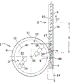
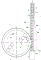
图1示出了按本发明的具有大致切向连接的挤出机的装置的垂直切面; Figure 1 shows a vertical section through the device of the present invention with approximately tangentially connected extruders;
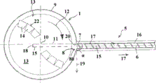
图2示出了图1的实施方式的水平切面; Figure 2 shows a horizontal section through the embodiment of Figure 1;
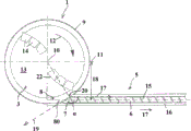
图3示出了具有最小偏移的另一实施方式; Figure 3 shows another embodiment with minimal offset;
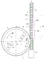
图4示出了具有更大偏移的另一实施方式; Figure 4 shows another embodiment with a larger offset;
图5到8示出了在螺杆壳体中具有凹口的实施方式。 Figures 5 to 8 show an embodiment with recesses in the screw housing.
具体实施方式 Detailed ways
在附图中描述的例子中全部示出了具有唯一一个螺杆例如单轴挤出机或者说单螺杆挤出机的输送机。然而作为替代方案也可以设置具有多个螺杆例如双轴或者多轴输送机或者挤出机尤其具有多个相同的具有至少相同直径d的螺杆的输送机。还可以看到,螺杆的旋转方向不是很重要;螺杆可以沿着或者逆着顺时针旋转。图1到4首先解释了工具关于螺杆输送方向的旋转方向。 The examples described in the drawings all show conveyors with a single screw, for example single-shaft extruders or single-screw extruders. Alternatively, however, it is also possible to provide a conveyor with a plurality of screws, for example a twin-screw or multi-screw conveyor or an extruder, in particular a plurality of identical screws with at least the same diameter d. It can also be seen that the direction of rotation of the screw is not critical; the screw can rotate either in or counter-clockwise. Figures 1 to 4 firstly explain the direction of rotation of the tool with respect to the conveying direction of the screw.
容器、螺杆或者拌和工具在附图中既不是按比例也不是相互间成比例地示出。比如说,事实上所述容器大多数比这里示出的更大或者所述螺杆比这里示出的更长。 The containers, screws or mixing means are not shown in the figures to scale or to one another. For example, the fact that most of the containers are larger than shown here or the screws are longer than shown here.
在图1和图2中示出的有利的用于准备或者说回收塑料材料的切碎压缩机-挤出机-组合具有圆柱形的容器或者说切碎压缩机或者说撕碎机1,其带有平坦的水平的底面2以及标准朝其定向的垂直的柱形罩面状的侧壁9。
The advantageous shredding compressor-extruder-combination shown in FIGS. 1 and 2 for preparing or recycling plastic material has a cylindrical container or shredding compressor or
在与底面2略微隔开的地方,最多侧壁9高度-从底面2到侧壁9的最上面的边缘进行测量-的大约10到20%、必要时更小的地方布置了平行于底面2定向的平坦的载体板或者说工具架13,其可以围绕中间的旋转轴线10沿着用箭头12标记的旋转方向或者说运动方向旋转,该旋转轴线同时是容器1的中心的中轴。所述载体板13通过马达21进行驱动,该马达位于容器1下面。在载体板13的上侧上布置了刀具或者说工具14例如切割刀,所述刀具与载体板13共同地形成了拌和和/或粉碎工具3。
At a slight distance from the
如示意性地示出,所述刀具14没有对称地布置在载体板13上,而是分开地构造、安装或者说布置在其沿着旋转方向或者说运动方向12指向的前面的边缘22上,从而能够对塑料材料产生特殊的机械影响。拌和以及粉碎工具3的径向最外面的边缘够到侧壁9的内表面附近大致容器1半径11的5%处。
As shown schematically, the
所述容器1在上面具有进料口,通过该进料口例如借助于输送机沿着箭头方向投入有待加工的物品例如由塑料材料层制成的东西。作为替代方案可以提出,封闭所述容器1并且至少可以在技术真空上抽真空,其中通过闸门系统置入材料。所述物品由环绕的拌和和/或粉碎工具3获得并且以拌和旋风卷30的形式进行高速旋转,其中物品沿着垂直的侧壁9升高并且近似在起作用的容器高度H的范围内通过重力作用再次向内并且向下回落到容器中间的区域内。容器1的起作用的高度H近似等于其内直径D。在容器1中形成了拌和旋风卷,其中材料不仅从上到下而且也沿着旋转方向12急速旋转。由此,这种装置可以由于拌和以及粉碎工具3或者说刀具14的特别布置仅仅以预先给出的旋转方向或者说运动方向12来运行,并且该旋转方向12不能轻易地或者不用进行额外改变地调转。
The
置入的塑料材料由旋转的拌和以及粉碎工具3粉碎、拌和,并且在此通过置入的机械摩擦能量进行加热并且软化,然而不是熔化。在容器1中确定的停留时间之后,均匀软化粘稠的然而不熔化的材料如下详细讨论地通过开口8从容器1中出去、置入挤出机5的进入区域并且在那里由螺杆6获取并且接下去进行熔化。
The inserted plastic material is comminuted, stirred by the rotating mixing and
在这种情况下唯一的粉碎以及拌和工具3的高度上,在容器1的侧壁9中构造上述开口8,通过该开口可以将预处理好的塑料材料从容器1的内部取出。所述材料移交给切向布置在容器1上的切碎压缩机5,其中挤出机5的壳体16具有位于其外罩壁中的进料口80用于有待由螺杆6获取的材料。这种实施方式具有以下优点,即所述螺杆6可以由图纸中下面的端部通过仅仅示意性示出的驱动装置进行驱动,从而能够由驱动装置不阻塞螺杆6的在附图中上面的端部。这实现了用于由螺杆6输送、塑化或者凝聚的塑料材料的排出口布置在所述右边的端部上,例如没有示出的挤出机头部形式的端部上。因此,可以不用螺杆6转向地通过排出口输送塑料材料,这在按图3和4的实施方式中不能轻易实现。
At the level of the only comminuting and mixing
所述进料口80与开口8处于材料输送连接之中或者说移交连接之中,并且在这种情况下直接、间接并且不用较长的中间件或者间隔件地与开口8连接。仅仅设置一个很短的移交区域。
The
在壳体16中,压缩的螺杆6围绕其纵轴线15可旋转地得到支承。该螺杆6和挤出机5的纵轴线15重合。该挤出机5沿着箭头17的方向输送材料。该挤出机5是已知的常规的挤出机,其中压缩软化的塑料材料并且由此将其熔化,并且该熔化物就在对置的一侧上在挤出机头部上出来。
In the
所述拌和和/或粉碎工具3或者说刀具14位于和挤出机5的中间的纵轴线15近似相同的高度上或者说平面上。所述刀具14的最外面的端部与螺杆6的接片充分隔开。
The mixing and/or comminution means 3 or
在按图1和2的实施方式中,所述挤出机5如已经提到地切向连接到容器1上或者说切向于其横截面延伸。所述挤出机5或者说螺杆6的中间的纵轴线15的假想的延长线反向于挤出机5的输送方向17向后,在附图中引导通过旋转轴线10的边上,而不与之相交。挤出机5或者说螺杆6的纵轴线在出口侧与容器1的与纵轴线5平行的从拌和和/或粉碎工具3的旋转轴线10沿着挤出机5的输送方向17指向外的径线11错开一段距离18。在这种情况下,挤出机5的纵轴线15的假想的向后的延长线没有穿过容器1的内部空间,而是紧贴地在其边上通过。
In the embodiment according to FIGS. 1 and 2 , the
所述距离18略微大于容器1的半径。由此,所述挤出机5略微向外偏移或者说进入区域略微更深。
Said
“反向”、“反转”或者“相反”这些概念在此理解为相互间矢量的定向,其不是锐角的,如下面详细解释的那样。 The terms “inverted”, “inverted” or “opposite” are understood here to mean an orientation of vectors relative to one another, which is not at an acute angle, as will be explained in more detail below.
换句话说,由旋转方向12的切向于拌和和/或粉碎工具3的最外面的点的回转圆或者说切向于在开口8上掠过的塑料材料定向的并且指向拌和和/或粉碎工具3的旋转方向或者说运动方向12的方向矢量19与挤出机5的输送方向的沿输送方向平行于中间的纵轴线15延伸的方向矢量17形成的标积在开口8的每个单独的点中或者说在沿径向就在开口8前面的区域内处处都是零或者负数,然而没有一处是正数。
In other words, the circle of revolution tangential to the outermost point of the mixing and/or
在图1和2中的进料口中,旋转方向12的方向矢量19与输送方向的方向矢量17的标积在开口8的每个点上都是负的。
In the feed openings in FIGS. 1 and 2 , the scalar product of the
输送方向的方向矢量17与旋转方向19的方向矢量之间的角度α在开口8的朝旋转方向20在最上游的点20中测量地或者说在开口8的最上游的边缘上测量地几乎最大为大约160°。
The angle α between the
如果沿着开口8向左也就是沿着旋转方向12继续前进,那么钝角α越来越大。在开口8的中间,方向矢量之间的角度大致为180°并且标积最大为负数,继续往左,角度甚至>180°并且标积再度略微降低,然而总是保持负数。
As one proceeds to the left along the
旋转方向19的方向矢量以及输送方向17的方向矢量之间的在图2中没有绘出的在开口8的中间或者说中央测量的角度β大致为175°。
The angle β between the direction vector of the direction of
按图2的装置是第一极限情况或者说极限值。在这种装置中实现了非常经济的填塞作用或者说特别有利的进料,并且这种装置尤其用于敏感的材料,所述材料在融化区域进行处理或者对于长条纹的物品有利。 The device according to FIG. 2 represents the first limiting case or limiting value. A very economical packing action or a particularly advantageous feed is achieved in such a device and is used in particular for sensitive materials which are processed in the melting zone or which are advantageous for long-striped articles.
在图3中示出了替代的实施方式,其中挤出机5不是切向地而是以其端面7连接到容器1上。螺杆6以及挤出机5的壳体16在开口8的范围内配合容器1内壁的轮廓并且平齐地缩回。没有挤出机5的部件会穿过开口8伸入容器1的内部空间。
An alternative embodiment is shown in FIG. 3 , in which the
所述距离18在此相当于容器1的半径11的大约15到20%并且大致相当于壳体16的内直径d的一半。由此,该实施方式示出了具有最小可能的偏差或者说距离18的第二极限情况或者说极限值,其中拌和和/或粉碎工具3的旋转或者说运动方向12至少略微反向于挤出机5的输送方向17,更确切地说在开口8的整个表面上。
The
所述标积在图3中在极限值的最上游的点20中刚好为零,该点靠在开口8的最上游的边缘上。输送方向的方向矢量17与旋转方向19的方向矢量之间的角度α在图3的点20中测量刚好为90°。如果沿着开口8向左也就是沿着旋转方向12继续前行,那么角度α越来越大并且形成>90°的钝角并且标积同时为负。然而,没有在开口8的哪个点上或者哪个区域中标积是正的或者角度α小于90°。由此不能一次性在开口8的部分区域内实现局部的过度供给,或者说不会在开口8的哪个区域内出现有害的过高的填塞作用。
The scalar product is exactly zero in FIG. 3 at the most
与纯粹的径向布置之间决定性的区别也在于此,因为在挤出机5的径向布置中在点20或者说在边缘20’中角度α<90°并且开口8的在附图中位于径线11右边或者说在其上游或者说在其入口侧的区域具有正的标积。由此能够在该区域内局部地收集熔化的合成物品。
The decisive difference from a purely radial arrangement also lies in this, since in the radial arrangement of the
在图4中示出了另一替代的实施方式,其中挤出机5在出口侧比在图3中偏移更多,然而不会像图1和2中那样切向。在这种情况下,如在图3中,挤出机5的纵轴线15的向后假想的延长线割线状地穿过容器1的内部空间。这会使得-沿容器1的圆周方向测量的-开口8比在按图3的实施方式中的更宽。所述距离18也相应地壁在图3中的更大,然而略微小于半径11。在点20中测量的角度α大约为150°,由此相对于图3的装置降低了填塞作用,这有利于特定的敏感的聚合物。从容器1看右边里面的边缘或者说壳体16的内壁切向地连接到容器1上,由此与图3不同的是没有构造钝的过渡边缘。在开口8的这个最下游的点中,在图4最左边,所述角度大致为180°。
Another alternative embodiment is shown in FIG. 4 , in which the
根据图1到4,讨论拌和工具关于螺杆6输送方向17的旋转方向的重要特性及优点,其与入口下游材料进入之后材料在螺杆6中的输送和加工紧密地共同作用。拌和工具的旋转方向与螺杆6壳体16的壁段105的特殊构造提供了重要的优点。
Based on FIGS. 1 to 4 , the important characteristics and advantages of the mixing tool with respect to the direction of rotation of the
根据图5到8,壁段105在长度L上连接到进料口80上。在壳体16的沿输送方向17直接连接到进料口80上的完全包围螺杆6的壁段105中构造凹口100,该凹口沿输送方向17从进料口80的-沿着输送方向17看-在最下游的点20或者说边缘20’在0.8d≤L≤9d、优选1d≤L≤7d的长度L上延伸,其中d是壁段105中螺杆6的直径。
According to FIGS. 5 to 8 , the
在图5到8中示出的容器1以及其连接到壳体16上的接口相应于如在图5到8中所示的容器以及接口。
The
所述凹口100改善了从容器3输入的材料的经济地进入并且以经济的方式将该材料导入螺杆6的通道中。如在图6所示,也可以在进料口80的区域内以及反向于输送方向17连接到进料口80上的区域内延伸其它如图6中所示的凹口101。然而也可以仅仅在进料口80前面延伸构造在壳体16中的带有其它凹口101的壁段,如在图7中所示。
The
现在提出,在壁段105中在凹口100中肋或者接片102从壳体16的内壁沿着到螺杆6的方向延伸。代替该肋或者接片102也可以设置起到相同作用的滑块。该堵住元件使得位于凹口中的材料输入螺杆。构造在壳体16内壁中的凹槽103或者类似的凹处也可以满足这种堵住元件的功能。所述凹槽103例如在图8中示出。
It is now provided that in the
所述堵住元件可以设置在凹口100中以及其它凹口101中,其中可以有利的是,所述堵住元件102、103在凹口100的整个长度上延伸或者说在其它凹口101的整个长度上延伸。然而也可以如图5所示,所述堵住元件仅仅在壁段105的长度的一部分区域上延伸。该堵住元件可以以点20或者说边缘20’开始并且在点110的高度前或者该高度上终止,壁段105的长度在该处终止。也可以所述堵住元件102、103仅仅在一个区域上延伸,该区域与点20或者说与边缘20’隔开并且也与点110隔开。
The blocking elements can be arranged in the
各个堵住元件102、103在凹口100中的长度LS可以为凹口长度L的60到100%,优选75到100%,其中L为0.8到9D,优选1到7D。所述堵住元件102、103优选开始于进料口的沿螺杆6输送方向下游的边缘20’或者进料口的最下游的点20。也可以只在与所述点20或者说边缘20’隔开预先给出的距离处开始所述堵住元件2、3,在进料口80的沿输送方向16最下游的点20或者说边缘20’处开始所述堵住元件。
The length LS of the
所述堵住元件102、103可以布置或者说构造在具有任意形状横截面的凹口100和/或凹口101中。如在图6和8中所示,所述壁段105具有沿输送方向17越来越细的凹口,尤其圆锥形越来越细的凹口,与此相对,壁段105如在图5和7中所示,具有基本上平行于输送方向17延伸的内壁面。根据图6,凹口100以及其它凹口101中的肋102平齐。
The blocking
大略有利的是,在凹口100以及其它凹口101中的堵住元件102、103平齐地布置。
It is substantially advantageous if the blocking
根据图7,凹口100以及其它凹口101中的肋102在其长度延伸上沿输送方向17与螺杆6的距离减小。
According to FIG. 7 , the
堵住元件102、103与螺杆6的包络线之间的距离也可以沿着输送方向减小或者保持恒定。
The distance between the blocking
对于一定的使用目的来说可以有利的是,各个堵住元件102、103沿着输送方向17平行于螺杆6的轴线笔直地延伸或者以螺旋的方式沿着螺杆的圆周包围该螺杆6,其中螺旋的螺距大于螺杆6的螺距。所述堵住元件102、103关于输送方向17的螺旋角为0°到75°。围绕螺杆6盘绕延伸的堵住元件2、3在附图中没有示出。
For certain purposes it can be advantageous if the
为了将材料转移到螺杆6中,尤其在跟随进入区域的凹口100的范围内进行转移时有利的是,所述肋102或者滑块有利地沿径向延伸到凹口100中或者说其它凹口101中并且示出了用于围绕螺杆6输送材料的止动件。
In order to transfer the material into the
可以将设置在凹口100中的堵住元件102、103延长到其它凹口101中并且由此构成连续的堵住元件。此外也有利的是,其它凹口101的内横截面相应于点20或者说边缘20’中凹口100的横截面。
The blocking
对于实际情况来说证实有利的是,壁段105中堵住元件102、103的数量以及由此凹口100的数量为A=d/K,其中d是螺杆6的以mm计的直径并且K是10到110尤其15到90范围内的值。由此可以为给出的螺杆直径确定堵住元件的分布在壁段105圆周上的对于良好材料加工来说所需的数量。
It has proven to be advantageous for practical situations if the number of blocking
显示出,通过设置在壁段105内部的堵住元件然而首先通过在该区域内构造凹口100实现对于材料或者说材料特性有利地输入或者说置入螺杆6的通道中。这通过在螺杆6出口处获得的、处理的或者说熔化的材料的改善的特性所占据。从拌和工具14置入进料口80的材料的方向也与凹口100的影响积极地共同作用。
It is shown that an advantageous introduction or insertion into the channel of the
对于材料特性的其它改善来说有针对性的是,包围凹口100的壁段105的至少一个部分段设有冷却单元120,其中在壳体16的壁中有利地设置包围壳体16的冷却罩面和/或冷却通道。
For a further improvement of the material properties it is pertinent to provide at least a partial section of the
当壳体16的构造凹口100的壁段105构造成可更换可使用到壳体16中的优选具有长度L的壳体部件时或者当所述凹口100构造在优选具有长度L的可更换可用到壳体16中的插口中时,简化按本发明的装置的构造。在这种情况下可以用没有示出的连接改造从点20或者说从边缘20’到点110的壁段并且通过其它具有相应堵住元件102、103的壁段105代替上述壁段。
When the
此外,由有待加工的或者说有待输送的材料确定堵住元件102、103的构造并且该构造也取决于材料的成分或者说随材料携带的脏物。
Furthermore, the configuration of the blocking
在沿输送方向17跟在壁段105后面的壳体段中可以任意地以常规形式构造通向出口30的螺杆6,该形式取决于所希望的材料加工或者材料处理。
In the housing section following the
实现壁段105的冷却的方式方法由技术人员选择:重要的是在螺杆6的壳体16的该区域中能够进行冷却的方案。
The manner in which the cooling of the
所述螺杆6至少在壁段105中优选在整个长度上具有恒定的外直径和/或核心直径。
The
凹口100的从壳体16到壁区域的过渡部分有利地构造成倒圆的;也可以是阶梯状的构造。
The transition of the
Claims (29)
Applications Claiming Priority (3)
| Application Number | Priority Date | Filing Date | Title |
|---|---|---|---|
| ATA1509/2011A AT512208B1 (en) | 2011-10-14 | 2011-10-14 | DEVICE FOR PREPARING PLASTIC MATERIAL |
| ATA1509/2011 | 2011-10-14 | ||
| PCT/AT2012/050158 WO2013052986A1 (en) | 2011-10-14 | 2012-10-12 | Apparatus for processing plastic material |
Publications (2)
| Publication Number | Publication Date |
|---|---|
| CN103857504A true CN103857504A (en) | 2014-06-11 |
| CN103857504B CN103857504B (en) | 2017-05-31 |
Family
ID=47142841
Family Applications (1)
| Application Number | Title | Priority Date | Filing Date |
|---|---|---|---|
| CN201280050421.4A Active CN103857504B (en) | 2011-10-14 | 2012-10-12 | Apparatus for preparing plastic materials |
Country Status (21)
| Country | Link |
|---|---|
| US (1) | US9266272B2 (en) |
| EP (1) | EP2766164B1 (en) |
| JP (1) | JP6076356B2 (en) |
| KR (1) | KR101744239B1 (en) |
| CN (1) | CN103857504B (en) |
| AT (1) | AT512208B1 (en) |
| AU (1) | AU2012323815B2 (en) |
| BR (1) | BR112014008870B1 (en) |
| CA (1) | CA2851662C (en) |
| DE (1) | DE202012012589U1 (en) |
| DK (1) | DK2766164T3 (en) |
| ES (1) | ES2565279T3 (en) |
| HU (1) | HUE027087T2 (en) |
| MX (1) | MX340974B (en) |
| PL (1) | PL2766164T3 (en) |
| RU (1) | RU2584278C2 (en) |
| SI (1) | SI2766164T1 (en) |
| TW (1) | TWI517958B (en) |
| UA (1) | UA109965C2 (en) |
| WO (1) | WO2013052986A1 (en) |
| ZA (1) | ZA201402096B (en) |
Cited By (1)
| Publication number | Priority date | Publication date | Assignee | Title |
|---|---|---|---|---|
| CN110382210A (en) * | 2017-03-30 | 2019-10-25 | 惠普发展公司,有限责任合伙企业 | Build Material Conveyor |
Families Citing this family (19)
| Publication number | Priority date | Publication date | Assignee | Title |
|---|---|---|---|---|
| AT504709B1 (en) * | 2006-11-23 | 2008-09-15 | Erema | METHOD AND DEVICE FOR INTRODUCING ADDITIVES |
| AT511362B1 (en) * | 2010-04-14 | 2014-01-15 | Erema | DEVICE FOR PREPARING PLASTIC MATERIAL |
| AT512209B1 (en) * | 2011-10-14 | 2015-02-15 | Erema | DEVICE FOR PREPARING PLASTIC MATERIAL |
| AT512208B1 (en) * | 2011-10-14 | 2015-02-15 | Erema | DEVICE FOR PREPARING PLASTIC MATERIAL |
| AT512223B1 (en) * | 2011-10-14 | 2015-02-15 | Erema | DEVICE FOR PREPARING PLASTIC MATERIAL |
| AT512149B1 (en) * | 2011-10-14 | 2015-02-15 | Erema | DEVICE FOR PREPARING PLASTIC MATERIAL |
| AT512145B1 (en) * | 2011-10-14 | 2015-02-15 | Erema | DEVICE FOR PREPARING PLASTIC MATERIAL |
| AT512205B1 (en) * | 2011-10-14 | 2015-02-15 | Erema | DEVICE FOR PREPARING PLASTIC MATERIAL |
| AT512148B1 (en) | 2011-10-14 | 2015-02-15 | Erema | DEVICE FOR PREPARING PLASTIC MATERIAL |
| AT512207B1 (en) * | 2011-10-14 | 2015-02-15 | Erema | DEVICE FOR PREPARING PLASTIC MATERIAL |
| AT512222B1 (en) | 2011-10-14 | 2015-02-15 | Erema | DEVICE FOR PREPARING PLASTIC MATERIAL |
| AT512212B1 (en) * | 2011-10-14 | 2015-02-15 | Erema | DEVICE FOR PREPARING PLASTIC MATERIAL |
| AT512146B1 (en) * | 2011-10-14 | 2015-02-15 | Erema | DEVICE FOR PREPARING PLASTIC MATERIAL |
| DE102015200680B4 (en) * | 2014-10-18 | 2016-05-25 | Haarslev Industries GmbH | Feed device of a belt drying system and method for controlling a feed device |
| AT517262A2 (en) * | 2015-06-03 | 2016-12-15 | Next Generation Recyclingmaschinen Gmbh | Processing plant for plastic material |
| US11583810B2 (en) | 2020-12-14 | 2023-02-21 | Industrial Technology Research Institute | Porous substrate structure and manufacturing method thereof |
| CN116175799B (en) * | 2023-02-15 | 2023-12-15 | 黄山贝诺科技有限公司 | System and method for preparing functionalized polyolefin under inert atmosphere |
| AT528143A1 (en) * | 2024-03-19 | 2025-10-15 | Erema Eng Recycling Maschinen & Anlagen Gmbh | Extruder for processing polymer materials |
| AT528259A1 (en) * | 2024-04-26 | 2025-11-15 | Erema Eng Recycling Maschinen & Anlagen Gmbh | Extruder for processing polymeric materials |
Citations (5)
| Publication number | Priority date | Publication date | Assignee | Title |
|---|---|---|---|---|
| EP0123771A1 (en) * | 1983-04-27 | 1984-11-07 | EREMA Engineering Recycling Maschinen und Anlagen Gesellschaft m.b.H. | Apparatus for compounding plastic material |
| EP0303929A2 (en) * | 1987-08-18 | 1989-02-22 | Indupack Ag | Apparatus for preparing thermoplastic products |
| US5783225A (en) * | 1993-12-21 | 1998-07-21 | Bacher; Helmut | Apparatus for processing thermoplastic synthetic plastics material |
| US5988865A (en) * | 1995-04-11 | 1999-11-23 | Bacher; Helmut | Device for preparing thermoplastic material |
| CN1549761A (en) * | 2001-07-02 | 2004-11-24 | Ī��������Һó��C.S.N.C. | Process and apparatus for producing filled thermoplastic polymers |
Family Cites Families (57)
| Publication number | Priority date | Publication date | Assignee | Title |
|---|---|---|---|---|
| US2927007A (en) | 1957-04-17 | 1960-03-01 | Braunschweigische Maschb Ansta | Apparatus for the treatment of animal and vegetable materials |
| DE2224209C3 (en) | 1972-05-18 | 1982-12-30 | Buckau-Walther AG, 4048 Grevenbroich | Device for ejecting the dry, leached chips from a diffusion tower |
| DE2839446C2 (en) | 1978-09-11 | 1980-09-25 | Thyssen Industrie Ag, 4300 Essen | Device for compacting and agglomerating plastic waste |
| AT368737B (en) | 1980-07-31 | 1982-11-10 | Oesterr Schiffswerften | DEVICE FOR PROCESSING THERMOPLASTIC PLASTIC MATERIAL |
| DE3231237A1 (en) | 1982-08-23 | 1984-02-23 | Dr. Herfeld GmbH & Co KG, 5982 Neuenrade | METHOD FOR COMPRESSING THERMOPLASTIC PLASTIC MATERIAL |
| GB2145351A (en) | 1983-08-24 | 1985-03-27 | Howden James & Co Ltd | Pulverizer |
| AT385234B (en) | 1984-08-01 | 1988-03-10 | Paracon Extrusionstech Gmbh | DEVICE FOR PROCESSING THERMOPLASTIC PLASTIC MATERIAL |
| AT387747B (en) * | 1986-10-10 | 1989-03-10 | Erema | DEVICE FOR PROCESSING PLASTIC MATERIAL |
| DE8716077U1 (en) | 1987-12-04 | 1988-02-11 | Plastmachines Gelderland, 8039 Puchheim | Device for processing thermoplastic material |
| JPH07112708B2 (en) * | 1991-05-02 | 1995-12-06 | ワイケイケイ株式会社 | Automatic conversion and supply device for colored molding material in injection molding machine |
| AT398772B (en) | 1992-04-30 | 1995-01-25 | Erema | METHOD AND DEVICE FOR RECYCLING FUMED PLASTIC MATERIAL |
| AT400315B (en) | 1994-03-01 | 1995-12-27 | Bacher Helmut | Device for degassing a thermoplastic polymer |
| CA2159320C (en) | 1993-06-08 | 1998-10-20 | Helmut Bacher | Device for degassing thermoplastics |
| KR100207175B1 (en) | 1993-12-21 | 1999-07-15 | 바케르 헬무트 | Device for processing thermoplastic materials |
| AU7622696A (en) | 1995-11-11 | 1997-06-05 | Schafer Elektrotechnik - Sondermaschinen | Process and device for the processing of components from mixed materials and other building materials mixed therewith and the use thereof |
| IT1295628B1 (en) | 1997-10-17 | 1999-05-24 | Gamma Meccanica Srl | EQUIPMENT FOR THE FEEDING OF A SCREW EXTRUDER WITH CRUSHED PLASTIC MATERIAL. |
| AT407235B (en) * | 1999-04-23 | 2001-01-25 | Bacher Helmut | DEVICE FOR CONTINUOUSLY RECYCLING PLASTIC MATERIAL, PREFERABLY POLYESTER |
| AT407970B (en) * | 1999-06-02 | 2001-07-25 | Bacher Helmut | DEVICE AND METHOD FOR PROCESSING, IN PARTICULAR THERMOPLASTIC, PLASTIC MATERIAL |
| JP2001026019A (en) | 1999-07-14 | 2001-01-30 | Sintokogio Ltd | A temperature control method in a waste plastic paint removing apparatus and a waste plastic paint removing apparatus. |
| JP4073580B2 (en) | 1999-07-19 | 2008-04-09 | 新東工業株式会社 | Recycling equipment for resin parts with coating film |
| AT411161B (en) * | 1999-09-22 | 2003-10-27 | Bacher Helmut | METHOD AND DEVICE FOR RECYCLING PET GOODS |
| AT407972B (en) | 1999-12-02 | 2001-07-25 | Bacher Helmut | DEVICE FOR PRE-TREATING AND SUBJECT PLASTIFICATING OR AGGLOMERING PLASTICS |
| AT412623B (en) * | 2000-04-26 | 2005-05-25 | Bacher Helmut | DEVICE AND METHOD FOR PREPARING THERMOPLASTIC PLASTIC GOODS |
| US20020125600A1 (en) | 2000-10-31 | 2002-09-12 | David Horne | Plastic recycling system and process |
| AT410298B (en) | 2001-06-11 | 2003-03-25 | Bacher Helmut | DEVICE FOR FILLING A SNAIL STORED IN A CASE AND METHOD FOR OPERATING SUCH A DEVICE |
| DE10140215A1 (en) | 2001-08-16 | 2003-02-27 | Novum 2000 Gmbh | Thermoplastic scrap processing machine for recycling of thermoplastic plastic materials, includes an additive feed unit prior to a mixer and screw extruder |
| AT411235B (en) | 2002-06-05 | 2003-11-25 | Bacher Helmut | Recycled thermoplastic processing plant comprises two evacuated mixing vessels with temperature sensors, an inlet side vacuum sluice and an outlet to an extruder |
| AT411038B (en) * | 2002-06-10 | 2003-09-25 | Bacher Helmut | Mixer for homogenization of recycled PET materials has angled blades to lift and disperse material below the tool and blade carrier disc |
| AT503334B1 (en) * | 2003-04-01 | 2010-06-15 | Erema | METHOD AND DEVICE FOR PLASTICIZING PLASTIC MATERIAL |
| AT413511B (en) * | 2003-06-05 | 2006-03-15 | Bacher Helmut | DEVICE FOR PREPARING PLASTIC MATERIAL FOR RECYCLING PURPOSES |
| AT413512B (en) * | 2003-06-05 | 2006-03-15 | Helmut Bacher | DEVICE FOR PREPARING PLASTIC MATERIAL FOR RECYCLING PURPOSES |
| AT413199B (en) * | 2004-03-17 | 2005-12-15 | Erema | DEVICE FOR PREPARING PLASTIC MATERIAL |
| AT413673B (en) * | 2004-07-16 | 2006-04-15 | Erema | DEVICE AND METHOD FOR PREPARING THERMOPLASTIC, RECYCLED PLASTIC MATERIAL |
| US20070102550A1 (en) * | 2005-11-07 | 2007-05-10 | Lin Ping H | Plastic grain cutting and transporting mechanism |
| AT503014B1 (en) | 2006-04-27 | 2007-07-15 | Schulz Helmuth | Device for the extrusion of thermoplastic synthetic materials for the production of plastic, comprises an extruder screw mounted on a housing having a plasticizing section at the inlet side, a degassing section and a conveying outlet |
| AT504709B1 (en) * | 2006-11-23 | 2008-09-15 | Erema | METHOD AND DEVICE FOR INTRODUCING ADDITIVES |
| AT504854B1 (en) * | 2007-02-15 | 2012-08-15 | Erema | METHOD AND DEVICE FOR PREPARING A MATERIAL |
| AT505595B1 (en) * | 2007-08-14 | 2009-04-15 | Erema | METHOD AND DEVICE FOR TREATING PLASTIC MATERIAL |
| AT506489B1 (en) * | 2008-02-14 | 2010-12-15 | Erema | METHOD AND DEVICE FOR INJECTION MOLDING OF PLASTIC MATERIAL |
| AT508951B1 (en) | 2009-04-17 | 2012-03-15 | Erema | METHOD AND ARRANGEMENT FOR RECYCLING PLASTIC |
| AT11398U1 (en) | 2009-08-20 | 2010-10-15 | Engel Austria Gmbh | 3-ZONE PLASTIC NECK WITH MIXING PART |
| EP2316562A1 (en) | 2009-10-29 | 2011-05-04 | Bühler AG | Method and device for the treatment of bulk material |
| AT511362B1 (en) * | 2010-04-14 | 2014-01-15 | Erema | DEVICE FOR PREPARING PLASTIC MATERIAL |
| AT509323B1 (en) * | 2010-04-16 | 2011-08-15 | Erema | METHOD AND DEVICE FOR PREPARING AND CLEANING A POLYMER MATERIAL |
| AT512209B1 (en) * | 2011-10-14 | 2015-02-15 | Erema | DEVICE FOR PREPARING PLASTIC MATERIAL |
| AT512146B1 (en) * | 2011-10-14 | 2015-02-15 | Erema | DEVICE FOR PREPARING PLASTIC MATERIAL |
| AT512222B1 (en) * | 2011-10-14 | 2015-02-15 | Erema | DEVICE FOR PREPARING PLASTIC MATERIAL |
| AT512205B1 (en) * | 2011-10-14 | 2015-02-15 | Erema | DEVICE FOR PREPARING PLASTIC MATERIAL |
| AT512208B1 (en) * | 2011-10-14 | 2015-02-15 | Erema | DEVICE FOR PREPARING PLASTIC MATERIAL |
| AT512223B1 (en) * | 2011-10-14 | 2015-02-15 | Erema | DEVICE FOR PREPARING PLASTIC MATERIAL |
| AT512149B1 (en) * | 2011-10-14 | 2015-02-15 | Erema | DEVICE FOR PREPARING PLASTIC MATERIAL |
| AT512212B1 (en) * | 2011-10-14 | 2015-02-15 | Erema | DEVICE FOR PREPARING PLASTIC MATERIAL |
| AT512207B1 (en) * | 2011-10-14 | 2015-02-15 | Erema | DEVICE FOR PREPARING PLASTIC MATERIAL |
| AT512148B1 (en) * | 2011-10-14 | 2015-02-15 | Erema | DEVICE FOR PREPARING PLASTIC MATERIAL |
| AT512147B1 (en) * | 2011-10-14 | 2015-02-15 | Erema | DEVICE FOR PREPARING PLASTIC MATERIAL |
| AT512145B1 (en) * | 2011-10-14 | 2015-02-15 | Erema | DEVICE FOR PREPARING PLASTIC MATERIAL |
| RU116402U1 (en) * | 2011-12-02 | 2012-05-27 | Федеральное Государственное Автономное Образовательное Учреждение Высшего Профессионального Образования "Дальневосточный Федеральный Университет" (Двфу) | DEVICE FOR PROCESSING THERMOPLASTES |
-
2011
- 2011-10-14 AT ATA1509/2011A patent/AT512208B1/en active
-
2012
- 2012-10-12 DK DK12781262.6T patent/DK2766164T3/en active
- 2012-10-12 SI SI201230487T patent/SI2766164T1/en unknown
- 2012-10-12 TW TW101137652A patent/TWI517958B/en active
- 2012-10-12 EP EP12781262.6A patent/EP2766164B1/en active Active
- 2012-10-12 AU AU2012323815A patent/AU2012323815B2/en active Active
- 2012-10-12 DE DE201220012589 patent/DE202012012589U1/en not_active Expired - Lifetime
- 2012-10-12 US US14/351,687 patent/US9266272B2/en active Active
- 2012-10-12 MX MX2014004445A patent/MX340974B/en active IP Right Grant
- 2012-10-12 RU RU2014119279/05A patent/RU2584278C2/en active
- 2012-10-12 HU HUE12781262A patent/HUE027087T2/en unknown
- 2012-10-12 JP JP2014534878A patent/JP6076356B2/en active Active
- 2012-10-12 KR KR1020147013015A patent/KR101744239B1/en active Active
- 2012-10-12 CA CA2851662A patent/CA2851662C/en active Active
- 2012-10-12 CN CN201280050421.4A patent/CN103857504B/en active Active
- 2012-10-12 WO PCT/AT2012/050158 patent/WO2013052986A1/en not_active Ceased
- 2012-10-12 BR BR112014008870-5A patent/BR112014008870B1/en active IP Right Grant
- 2012-10-12 ES ES12781262.6T patent/ES2565279T3/en active Active
- 2012-10-12 PL PL12781262T patent/PL2766164T3/en unknown
- 2012-12-10 UA UAA201404481A patent/UA109965C2/en unknown
-
2014
- 2014-03-20 ZA ZA2014/02096A patent/ZA201402096B/en unknown
Patent Citations (6)
| Publication number | Priority date | Publication date | Assignee | Title |
|---|---|---|---|---|
| EP0123771A1 (en) * | 1983-04-27 | 1984-11-07 | EREMA Engineering Recycling Maschinen und Anlagen Gesellschaft m.b.H. | Apparatus for compounding plastic material |
| JPS59207223A (en) * | 1983-04-27 | 1984-11-24 | エレマ・エンジニアリング−リサイクリング−・マシネン−アンラ−ゲン・ゲゼルシヤフト・ミツト・ベシユレンクテル・ハフトウング | Device for machining thermoplastic synthetic resin material |
| EP0303929A2 (en) * | 1987-08-18 | 1989-02-22 | Indupack Ag | Apparatus for preparing thermoplastic products |
| US5783225A (en) * | 1993-12-21 | 1998-07-21 | Bacher; Helmut | Apparatus for processing thermoplastic synthetic plastics material |
| US5988865A (en) * | 1995-04-11 | 1999-11-23 | Bacher; Helmut | Device for preparing thermoplastic material |
| CN1549761A (en) * | 2001-07-02 | 2004-11-24 | Ī��������Һó��C.S.N.C. | Process and apparatus for producing filled thermoplastic polymers |
Cited By (3)
| Publication number | Priority date | Publication date | Assignee | Title |
|---|---|---|---|---|
| CN110382210A (en) * | 2017-03-30 | 2019-10-25 | 惠普发展公司,有限责任合伙企业 | Build Material Conveyor |
| CN110382210B (en) * | 2017-03-30 | 2023-03-28 | 惠普发展公司,有限责任合伙企业 | Build material conveyor |
| US11964433B2 (en) | 2017-03-30 | 2024-04-23 | Hewlett-Packard Development Company, L.P. | Build material conveyors |
Also Published As
| Publication number | Publication date |
|---|---|
| US9266272B2 (en) | 2016-02-23 |
| AT512208A1 (en) | 2013-06-15 |
| BR112014008870B1 (en) | 2020-07-28 |
| RU2584278C2 (en) | 2016-05-20 |
| MX340974B (en) | 2016-08-02 |
| UA109965C2 (en) | 2015-10-26 |
| CA2851662C (en) | 2018-05-22 |
| RU2014119279A (en) | 2015-11-20 |
| JP2014534910A (en) | 2014-12-25 |
| AT512208B1 (en) | 2015-02-15 |
| KR20140079478A (en) | 2014-06-26 |
| PL2766164T3 (en) | 2016-06-30 |
| DE202012012589U1 (en) | 2013-07-05 |
| ZA201402096B (en) | 2015-03-25 |
| AU2012323815B2 (en) | 2015-08-20 |
| ES2565279T3 (en) | 2016-04-01 |
| WO2013052986A1 (en) | 2013-04-18 |
| AU2012323815A1 (en) | 2014-05-15 |
| JP6076356B2 (en) | 2017-02-08 |
| EP2766164A1 (en) | 2014-08-20 |
| HK1200760A1 (en) | 2015-08-14 |
| CA2851662A1 (en) | 2013-04-18 |
| BR112014008870A2 (en) | 2017-04-25 |
| TW201332731A (en) | 2013-08-16 |
| US20140234462A1 (en) | 2014-08-21 |
| MX2014004445A (en) | 2014-09-22 |
| KR101744239B1 (en) | 2017-06-07 |
| CN103857504B (en) | 2017-05-31 |
| HUE027087T2 (en) | 2016-08-29 |
| EP2766164B1 (en) | 2015-12-16 |
| DK2766164T3 (en) | 2016-03-14 |
| TWI517958B (en) | 2016-01-21 |
| SI2766164T1 (en) | 2016-04-29 |
Similar Documents
| Publication | Publication Date | Title |
|---|---|---|
| CN103857504B (en) | Apparatus for preparing plastic materials | |
| CN103857502B (en) | For pretreatment and subsequent plasticizing plastic material device | |
| CN103857503B (en) | For the device for reclaiming purpose to synthetic material pretreatment and convey, plastify or coalesce | |
| KR101525381B1 (en) | Apparatus for processing plastics material | |
| CN103874568B (en) | Devices for the pretreatment and subsequent conveying, plasticizing or coalescing of synthetic materials | |
| CN103874566B (en) | Apparatus for processing plastic material | |
| KR101744253B1 (en) | Apparatus for precessing plastic material | |
| TWI501851B (en) | Apparatus for the treatment of plastics material | |
| TWI569942B (en) | Apparatus for the treatment of palstics material | |
| TWI524977B (en) | Apparatus for the treatment of plastics material | |
| DK2766167T3 (en) | An apparatus for processing plastics material | |
| KR101718686B1 (en) | Apparatus for processing plastic material | |
| CN103874565A (en) | Apparatus for processing plastic material | |
| ZA200203781B (en) | Apparatus for pre-treated and subsequent plastification or agglomeration of synthetic plastic material. | |
| HK1200760B (en) | Apparatus for processing plastic material |
Legal Events
| Date | Code | Title | Description |
|---|---|---|---|
| C06 | Publication | ||
| PB01 | Publication | ||
| C10 | Entry into substantive examination | ||
| SE01 | Entry into force of request for substantive examination | ||
| GR01 | Patent grant | ||
| GR01 | Patent grant |