CN103808237A - Tool structure for measuring plunger bottom clearance groove depths - Google Patents
Tool structure for measuring plunger bottom clearance groove depths Download PDFInfo
- Publication number
- CN103808237A CN103808237A CN201410087940.9A CN201410087940A CN103808237A CN 103808237 A CN103808237 A CN 103808237A CN 201410087940 A CN201410087940 A CN 201410087940A CN 103808237 A CN103808237 A CN 103808237A
- Authority
- CN
- China
- Prior art keywords
- lining
- flat position
- dead head
- cloudy
- spring
- Prior art date
- Legal status (The legal status is an assumption and is not a legal conclusion. Google has not performed a legal analysis and makes no representation as to the accuracy of the status listed.)
- Pending
Links
- 238000005259 measurement Methods 0.000 claims abstract description 6
- 210000004907 gland Anatomy 0.000 claims description 7
- PEDCQBHIVMGVHV-UHFFFAOYSA-N Glycerine Chemical compound OCC(O)CO PEDCQBHIVMGVHV-UHFFFAOYSA-N 0.000 claims description 5
- FGRBYDKOBBBPOI-UHFFFAOYSA-N 10,10-dioxo-2-[4-(N-phenylanilino)phenyl]thioxanthen-9-one Chemical compound O=C1c2ccccc2S(=O)(=O)c2ccc(cc12)-c1ccc(cc1)N(c1ccccc1)c1ccccc1 FGRBYDKOBBBPOI-UHFFFAOYSA-N 0.000 description 1
- 230000009286 beneficial effect Effects 0.000 description 1
- 238000002347 injection Methods 0.000 description 1
- 239000007924 injection Substances 0.000 description 1
- 238000009434 installation Methods 0.000 description 1
- 238000000034 method Methods 0.000 description 1
- 238000012986 modification Methods 0.000 description 1
- 230000004048 modification Effects 0.000 description 1
- 230000001737 promoting effect Effects 0.000 description 1
- 239000000243 solution Substances 0.000 description 1
- 239000002699 waste material Substances 0.000 description 1
Images

Landscapes
- A Measuring Device Byusing Mechanical Method (AREA)
Abstract
The invention relates to a tool structure for measuring plunger bottom clearance groove depths. The tool structure comprises a base, a first assembling unit and a measuring unit, wherein the first assembling unit is perpendicular to the measuring unit. Second assembling units are further arranged on the base relative to the first assembling unit at intervals. The tool structure is simple and convenient to install, the first assembling unit and the second assembling units are utilized to effectively achieve horizontal positioning of plungers, standard positioning of the plungers is achieved by arranging flat position columns, accuracy in plunger bottom clearance groove measurement is guaranteed, and the tool structure is flexible and convenient to adjust and effectively achieves depth measurement of massive plunger bottom clearance grooves of different sizes.
Description
Technical field
The present invention relates to tool structure, relate in particular to a kind of for measuring the tool structure of plunger bottom clearance groove depth.
Background technology
Plunger matching parts is formed by plunger and plunger bushing precision-fit, delivery valve matching parts (being made up of delivery valve and delivery valve seat) is equipped with in its top, plunger can be divided into A type, Type B, K type, AD type, P type etc. by its applicable injection pump difference, to meet the demand of different diesel engines.At present, need to measure the degree of depth of the bottom clearance groove of plunger end according to the demand of product drawing, due to the production in enormous quantities of plunger, tradition utilizes mode that survey instrument is measured to possess to waste time and energy, measure not problem accurately, not only improve drainage of human resources cost, also greatly affected processing progress and production efficiency.
Summary of the invention
The applicant, for above-mentioned existing issue, is studied improvement, provides a kind of for measuring the tool structure of plunger bottom clearance groove depth, has effectively realized the depth survey to plunger bottom clearance groove in enormous quantities.
The technical solution adopted in the present invention is as follows:
For measuring a tool structure for plunger bottom clearance groove depth, comprise base, comprise vertically arranged the first assembly unit and measuring unit each other, on base, also arrange the second assembly unit in interval with respect to the first assembly unit;
The concrete structure of described the first assembly unit is as follows:
Comprise positive dead head, swivel nut and described positive dead head are spirally connected, one end of positive top lining stretch into described positive dead head and with described swivel nut butt, in described swivel nut, install the second spring, sun toply runs through the top lining of described sun and is connected with described the second spring;
The concrete structure of described measuring unit is as follows:
Comprise gauge stand, lining through-going device is in described gauge stand, and one end of dial gauge is stretched into described lining and stretched into the top butt each other of measurement of lining with one end, is positioned at one end that described dial gauge stretches into lining (2) and is also set with the first spring;
The concrete structure of described the second assembly unit is as follows:
Comprise cloudy dead head, described cloudy dead head and gland nut are spirally connected, and cloudy Finial device connects in described cloudy dead head and with one end of the annular knurl pull handle that runs through gland nut, is positioned at cloudy dead head, in the cloudy top lining of the top periphery returning apparatus of the moon.
Its further technical scheme is:
Be positioned at the flat position of returning apparatus column base on base, be positioned at the flat position of column base suit, flat position post lining, one end of flat position post is stretched into described flat position post lining and is connected with the one end that is installed on the 3rd spring in the post of flat position, and the other end of the 3rd spring connects base.
Beneficial effect of the present invention is as follows:
The present invention is simple in structure, easy for installation, utilize the first assembly unit and the second assembly unit effectively to realize the horizontal location of plunger, realize the origin reference location to plunger by arranging flat position post, guarantee the accuracy that plunger bottom clearance groove is measured, flexible adjustment is convenient, has effectively realized depth survey in enormous quantities, different size plunger bottom clearance groove.
Accompanying drawing explanation
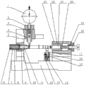
Fig. 1 is front view of the present invention.
Fig. 2 is the side view of Fig. 1.
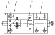
Fig. 3 is the vertical view of Fig. 1.
Wherein: 1, dial gauge; 2, lining; 3, the first spring; 4, measure top; 5, gauge stand; 6, hold-down bolt; 7, the second spring; 8, swivel nut; 9, positive top lining; 10, positive dead head; 11, sun is top; 12, base; 13, flat position column base; 14, the 3rd spring; 15, dog screw; 16, flat position post lining; 17, flat position post; 18, annular knurl pull handle; 19, gland nut; 20, the 4th spring; 21, cloudy top; 22, cloudy top lining; 23, cloudy dead head.
Embodiment
Below in conjunction with accompanying drawing, the specific embodiment of the present invention is described.
As shown in Figure 1, Figure 2 and Figure 3, for measuring a tool structure for plunger bottom clearance groove depth, comprise base 12, comprise vertically arranged the first assembly unit and measuring unit each other, on base 12, also arrange the second assembly unit in interval with respect to the first assembly unit;
The concrete structure of the first assembly unit is as follows:
Comprise positive dead head 10, swivel nut 8 is spirally connected with positive dead head 10, sun top lining 9 one end stretch into positive dead head 10 and with described swivel nut 8 butts, at interior device the second spring 7 of swivel nut 8, sun top 11 runs through positive top lining 9 and is connected with one end of described the second spring 7, the other end of the second spring 7 and hold-down bolt 6 butts, hold-down bolt 6 is spirally connected with swivel nut 8;
The concrete structure of measuring unit is as follows:
Comprise gauge stand 5, lining 2 through-going devices are in described gauge stand 5, and one end of dial gauge 1 is stretched into described lining 2 and stretched into measurement top 4 butt each other of lining 2 with one end, are positioned at one end that dial gauge 1 stretches into lining 2 and are also set with the first spring 3.
The concrete structure of described the second assembly unit is as follows:
Comprise cloudy dead head 23, cloudy dead head 23 is spirally connected with gland nut 19, cloudy top 21 are installed on described cloudy dead head 23 and connect with one end of the annular knurl pull handle 18 that runs through gland nut 19, be positioned at described cloudy dead head 23, in the cloudy top lining 22 of periphery returning apparatus of the moon top 21, be also set with the 4th spring 20 in the periphery of annular knurl pull handle 18.
Be positioned at the flat position of returning apparatus column base 13 on base 12, be positioned at the flat position of column base 13 suits, flat position post lining 16, one end of flat position post 17 is stretched into described flat position post lining 16 and is connected with the one end that is installed on the 3rd spring 14 in the post 17 of flat position, the other end of the 3rd spring 14 connects base 12, and above-mentioned flat position post 17 is locked by dog screw 15.
Specific works process of the present invention is as follows:
As shown in Figure 1, first the center pit of plunger one end and the cone end of sun top 11 are connected, the stressed sun top 11 that makes of the second spring 7 inwardly shrinks, flat plane and the flat position post 17 of adjusting plunger connect simultaneously, guarantee in proper order measuring basis, due to the interior device of flat position column base 13 the 3rd spring 14, make flat position post 17 there is retractility, flexible adjustment, then by promoting annular knurl pull handle 18, make with the moon top 21 of its end butt from stretch out in the top lining 22 of the moon and with the other end butt of plunger, now the bottom clearance groove of plunger contacts with measurement top 4, by with measure dial gauge 1 observed reading of top 4 butts, check that the degree of depth of this bottom clearance groove is whether within product size requires.
More than describing is explanation of the invention, is not the restriction to invention, and limited range of the present invention, referring to claim, within protection scope of the present invention, can be done any type of modification.
Claims (2)
1. one kind for measuring the tool structure of plunger bottom clearance groove depth, comprise base (12), it is characterized in that: comprise vertically arranged the first assembly unit and measuring unit each other, upper at described base (12), also arrange the second assembly unit in interval with respect to the first assembly unit;
The concrete structure of described the first assembly unit is as follows:
Comprise positive dead head (10), swivel nut (8) is spirally connected with described positive dead head (10), sun top lining (9) one end stretch into described positive dead head (10) and with described swivel nut (8) butt, device the second spring (7) in described swivel nut (8), sun top (11) runs through the top lining of described sun (9) and is connected with described the second spring (7);
The concrete structure of described measuring unit is as follows:
Comprise gauge stand (5), lining (2) through-going device is in described gauge stand (5), one end of dial gauge (1) is stretched into described lining (2) and is stretched into measurement top (4) butt each other of lining (2) with one end, is positioned at one end that described dial gauge (1) stretches into lining (2) and is also set with the first spring (3);
The concrete structure of described the second assembly unit is as follows:
Comprise cloudy dead head (23), described cloudy dead head (23) is spirally connected with gland nut (19), cloudy top (21) are installed on described cloudy dead head (23) and connect with one end of the annular knurl pull handle (18) that runs through gland nut (19), be positioned at described cloudy dead head (23), in the cloudy top lining of periphery returning apparatus (22) of described the moon top (21).
2. as claimed in claim 1 a kind of for measuring the tool structure of plunger bottom clearance groove depth, it is characterized in that: be positioned at the upper returning apparatus flat position column base of described base (12) (13), be positioned at described flat position column base (13) suit flat position post lining (16), one end of flat position post (17) is stretched into described flat position post lining (16) and is connected with the one end that is installed on the 3rd spring (14) in flat position post (17), and the other end of described the 3rd spring (14) connects base (12).
Priority Applications (1)
| Application Number | Priority Date | Filing Date | Title |
|---|---|---|---|
| CN201410087940.9A CN103808237A (en) | 2014-03-12 | 2014-03-12 | Tool structure for measuring plunger bottom clearance groove depths |
Applications Claiming Priority (1)
| Application Number | Priority Date | Filing Date | Title |
|---|---|---|---|
| CN201410087940.9A CN103808237A (en) | 2014-03-12 | 2014-03-12 | Tool structure for measuring plunger bottom clearance groove depths |
Publications (1)
| Publication Number | Publication Date |
|---|---|
| CN103808237A true CN103808237A (en) | 2014-05-21 |
Family
ID=50705361
Family Applications (1)
| Application Number | Title | Priority Date | Filing Date |
|---|---|---|---|
| CN201410087940.9A Pending CN103808237A (en) | 2014-03-12 | 2014-03-12 | Tool structure for measuring plunger bottom clearance groove depths |
Country Status (1)
| Country | Link |
|---|---|
| CN (1) | CN103808237A (en) |
Cited By (2)
| Publication number | Priority date | Publication date | Assignee | Title |
|---|---|---|---|---|
| CN104864830A (en) * | 2015-05-13 | 2015-08-26 | 无锡市苏立成汽车空调压缩机有限公司 | Tool for detecting width of installation groove of swash plate of compressor |
| CN108061505A (en) * | 2017-12-11 | 2018-05-22 | 重庆市银钢通科技有限公司 | A kind of keyway depth measurement device |
Citations (6)
| Publication number | Priority date | Publication date | Assignee | Title |
|---|---|---|---|---|
| US4642900A (en) * | 1985-07-08 | 1987-02-17 | Kent-Moore Corporation | Shim selector |
| US4651430A (en) * | 1985-12-19 | 1987-03-24 | Vasku George O | Snap gage |
| US7581330B1 (en) * | 2008-01-29 | 2009-09-01 | Redmond David W | Gauge device for measuring the inner diameter of engine related bores |
| CN201926413U (en) * | 2010-11-01 | 2011-08-10 | 仪征威业油泵油嘴有限公司 | Tool for inspecting distance from chute to end face |
| CN202278492U (en) * | 2011-10-09 | 2012-06-20 | 山东鑫亚工业股份有限公司 | Special clamp for machining oil distribution groove on plunger piston of oil injection pump |
| CN203719601U (en) * | 2014-03-12 | 2014-07-16 | 无锡威孚马山油泵油嘴有限公司 | Tool structure used for measuring depth of top clearance groove of plunger |
-
2014
- 2014-03-12 CN CN201410087940.9A patent/CN103808237A/en active Pending
Patent Citations (6)
| Publication number | Priority date | Publication date | Assignee | Title |
|---|---|---|---|---|
| US4642900A (en) * | 1985-07-08 | 1987-02-17 | Kent-Moore Corporation | Shim selector |
| US4651430A (en) * | 1985-12-19 | 1987-03-24 | Vasku George O | Snap gage |
| US7581330B1 (en) * | 2008-01-29 | 2009-09-01 | Redmond David W | Gauge device for measuring the inner diameter of engine related bores |
| CN201926413U (en) * | 2010-11-01 | 2011-08-10 | 仪征威业油泵油嘴有限公司 | Tool for inspecting distance from chute to end face |
| CN202278492U (en) * | 2011-10-09 | 2012-06-20 | 山东鑫亚工业股份有限公司 | Special clamp for machining oil distribution groove on plunger piston of oil injection pump |
| CN203719601U (en) * | 2014-03-12 | 2014-07-16 | 无锡威孚马山油泵油嘴有限公司 | Tool structure used for measuring depth of top clearance groove of plunger |
Cited By (2)
| Publication number | Priority date | Publication date | Assignee | Title |
|---|---|---|---|---|
| CN104864830A (en) * | 2015-05-13 | 2015-08-26 | 无锡市苏立成汽车空调压缩机有限公司 | Tool for detecting width of installation groove of swash plate of compressor |
| CN108061505A (en) * | 2017-12-11 | 2018-05-22 | 重庆市银钢通科技有限公司 | A kind of keyway depth measurement device |
Similar Documents
| Publication | Publication Date | Title |
|---|---|---|
| CN204413569U (en) | A kind of spool pressing machine | |
| CN103808237A (en) | Tool structure for measuring plunger bottom clearance groove depths | |
| CN201327369Y (en) | Device for measuring assembly height of diesel engine ejector | |
| CN203719601U (en) | Tool structure used for measuring depth of top clearance groove of plunger | |
| CN204854737U (en) | 3D gravity pendulum -type laser demarcation device | |
| CN203881286U (en) | A combined piston coaxiality detection measuring tool | |
| CN205860943U (en) | One stretches out detecting tool for detecting height | |
| CN203096766U (en) | Height-adjustable inspection well device | |
| CN204359259U (en) | A kind of francis turbine runner surveys circle frame | |
| CN203148355U (en) | Special measurement instrument for shaft hole of key slot of movable sleeve of bulldozer | |
| HK1203751A2 (en) | Solar tracking two-dimensional bracket and its bearing seat structure | |
| CN204825774U (en) | General type over -and -under type wave -height gauge support | |
| CN203570262U (en) | Fixed rack device for oil-well gas valve replacement under pressure | |
| CN203037880U (en) | Adjustable horizontal rain gage bucket | |
| CN206161226U (en) | Measurement device for internal wave horizontal force | |
| CN103900513A (en) | Lower measuring mechanism used for plunger steel ball automatic measuring riveting press | |
| CN203798335U (en) | Lower measurement mechanism for plunger steel ball automatic measurement riveting machine | |
| CN205745047U (en) | A kind of firm spring | |
| CN211006658U (en) | Adjustable combined type embedded anchor rod structure | |
| CN203901256U (en) | Adjustable steel structure processing jig frame | |
| CN202393330U (en) | Chamfering depth measurement tool | |
| CN202734753U (en) | Sensor for testing deformation degree of mined coal seam floor | |
| CN205129445U (en) | Frock is used in processing of engine end cover | |
| CN203383517U (en) | Accurate steel column axis positioning regulator | |
| CN205860996U (en) | A kind of easy bearing inner race detection device |
Legal Events
| Date | Code | Title | Description |
|---|---|---|---|
| C06 | Publication | ||
| PB01 | Publication | ||
| C53 | Correction of patent of invention or patent application | ||
| CB03 | Change of inventor or designer information |
Inventor after: Pu Mingjin Inventor after: Jiu Yingying Inventor before: Jiu Yingying |
|
| COR | Change of bibliographic data |
Free format text: CORRECT: INVENTOR; FROM: MIAO YINGYING TO: PU MINGJIN MIAO YINGYING |
|
| C10 | Entry into substantive examination | ||
| SE01 | Entry into force of request for substantive examination | ||
| WD01 | Invention patent application deemed withdrawn after publication | ||
| WD01 | Invention patent application deemed withdrawn after publication |
Application publication date: 20140521 |