Summary of the invention
Task of the present invention is to provide a kind of and the power drive mechanism for making vehicle to run can be doubled as to the power for making dust collection mechanism work simultaneously and use and reduce power configuration quantity and save energy consumption to embody, reduce manufacturing cost and use cost, alleviate deadweight and alleviate the dust-absorption cleaning vehicle of inspection difficulty.
Task of the present invention completes like this, a kind of dust-absorption cleaning vehicle, comprise a chassis, the left end on this chassis is provided with a driven live axle, one end and the other end at this driven live axle are respectively provided with a driven road wheel, the right-hand member on chassis is provided with a positive transport wheel axle, is respectively provided with a positive transport wheel at one end and the other end of this positive transport wheel axle, be successively set on from left to right a headstock, a power drive mechanism, a fuel tank and a garbage collection box on chassis, wherein, power drive mechanism is connected with described positive transport wheel through-drive, one dust collection mechanism, this dust collection mechanism is arranged on chassis, and with airborne the top corresponding to described power drive mechanism, pair of discs broom cleaning agency, this pair of discs broom cleaning agency is the left end on described chassis with the stateful connection that corresponds to each other, and corresponding to the left side of described driven road wheel, one dedusting dolly, this dedusting dolly is connected to the right-hand member on described chassis, and be connected with the bottom of described garbage collection box, communicate with the garbage collection box chamber of garbage collection box simultaneously, and this garbage collection box chamber communicates with described dust collection mechanism, described pair of discs broom cleaning agency is connected with the distributing valve oil circuit being arranged on chassis, and this distributing valve is connected with the oil pump oil circuit being arranged in fuel tank, be characterised in that also include one be arranged on described chassis for described power drive mechanism and described dust collection mechanism being formed each other to the be in transmission connection blower fan power transition transmission mechanism of relation of the relation of being in transmission connection or releasing, wherein: when described dust-absorption cleaning vehicle is during in state to road-cleaning, by described blower fan power transition transmission mechanism, power drive mechanism and dust collection mechanism are formed to the relation of being in transmission connection each other, and when dust-absorption cleaning vehicle is during in transport condition to the non-cleaning of road, make the relation broken that is mutually in transmission connection between power drive mechanism and dust collection mechanism by blower fan power transition transmission mechanism.
In a specific embodiment of the present invention, described power drive mechanism comprises motor, engine spindle large drive wheel, the little drive of engine spindle, motor large drive wheel driving-belt, motor brief biography driving wheel driving-belt, gearbox, gearbox power input drive, gearbox power output drive wheel, gearbox power output drive wheel driving-belt, transition power transmission shaft, transition power transmission shaft deceleration transmission wheel driving-belt, deceleration large drive wheel and positive transport wheel through-drive wheel, motor is arranged on described chassis, and be positioned at the left side of described fuel tank, engine spindle large drive wheel is fixed on one end of the engine spindle of motor, the little drive of engine spindle is fixed on the other end of engine spindle, one end of motor large drive wheel driving-belt is nested with at engine spindle large drive wheel, and the other end and described dust collection mechanism are in transmission connection, one end of motor brief biography driving wheel driving-belt is nested with on the little drive of engine spindle, the other end is nested with on gearbox power input drive, gearbox is arranged on chassis, and corresponding to the below of fuel tank, gearbox power input drive is fixed on the gearbox power input shaft of gearbox, gearbox power output drive wheel is fixed on the speed changing box power output shaft of gearbox, transition power transmission shaft is bearing in transition transmission shafts bearing rotationally with horizontally-arranged state, and transition transmission shafts bearing is fixed on chassis, be fixed with a transition transmission shaft driven wheel in one end of this transition power transmission shaft, and be fixed with a transition power transmission shaft transition drive at the other end of transition power transmission shaft, one end of gearbox power output drive wheel driving-belt is nested with on transition power transmission shaft transition drive, and the other end is nested with on gearbox power output drive wheel, one end of transition power transmission shaft deceleration transmission wheel driving-belt is nested with on transition transmission shaft driven wheel, the other end is nested with on deceleration large drive wheel, deceleration large drive wheel is fixed on deceleration large drive wheel axle, and deceleration large drive wheel axle is bearing on deceleration large drive wheel axle bed rotationally with horizontal boom state, this deceleration large drive wheel axle bed is fixed on described chassis, and deceleration large drive wheel has a sub-drive, on this sub-drive, be equipped with one end of a sub-drive driving-belt, and the other end of sub-drive driving-belt is nested with on positive transport wheel through-drive wheel, this positive transport wheel through-drive wheel is fixed on described positive transport wheel axle, when described dust-absorption cleaning vehicle is during in state to road-cleaning, make described motor large drive wheel driving-belt in tensioner state by described blower fan power transition transmission mechanism, motor large drive wheel driving-belt and dust collection mechanism form the relation of being in transmission connection each other, and drive described dust collection mechanism to work by motor large drive wheel driving-belt, and when dust-absorption cleaning vehicle is during in transport condition to the non-cleaning of road, make motor large drive wheel driving-belt in relaxed state by blower fan power transition transmission mechanism, relation broken is in transmission connection between motor large drive wheel driving-belt and dust collection mechanism, on described chassis and in the position corresponding to described fuel tank, be provided with a tank support with airborne, fuel tank is arranged on the top of this tank support, the position of described gearbox on chassis is corresponding to the bottom of tank support, described transition transmission shafts bearing is fixed on tank support, in the garbage collection box chamber of described garbage collection box and be positioned on the diapire in garbage collection box chamber and be fixed with a garbage collection box interface, on this garbage collection box interface, be connected with one for rubbish being imported to the rubbish ingress pipe in garbage collection box chamber, described dedusting dolly is connected with this garbage collection box interface in the bottom corresponding to garbage collection box.
In another specific embodiment of the present invention, in the garbage collection box chamber of described garbage collection box every being provided with a water tank, in water tank, be provided with a water tank demarcation strip, the water tank roof of the upper end of this water tank demarcation strip and water tank is fixed, and stretch towards the below of water tank with vertical cantilever state lower end, and the space between the lower end of this water tank demarcation strip and the tank bottom wall of water tank is configured to airway, wherein: the region that is positioned at the left side of water tank demarcation strip is configured to dedusting tube chamber, and the region that is positioned at the right side of water tank demarcation strip is configured to outlet chamber, between dedusting tube chamber and outlet chamber, connected by described airway, in dedusting tube chamber, be provided with a dust removing tube, the dedusting tube chamber roof of the upper end of this dust removing tube and dedusting tube chamber is fixed, and stretch towards the below of dedusting tube chamber with vertical cantilever state the lower end of dust removing tube and the dust removing tube dust mouth of this dust removing tube and be poured between the water surface of water of water tank and maintain spacing, on the water tank roof of described water tank and offering one corresponding to the position of described outlet chamber for the air in outlet chamber being caused to extraneous outlet chamber gas outlet, bottom at water tank is provided with blowoff valve, and on the left side wall of water tank, be provided with water inlet interface and the overflow pipe for introduce water in water tank, this overflow pipe is positioned at into the below of water interface, also form and have one to cross dirt chamber on the top in the garbage collection box chamber of garbage collection box, cross between dirt chamber and garbage collection box chamber and be provided with screen pack at this, and offer a dust mouth in mistake dirt chamber towards the crossing on the wall of dirt chamber of a side of described dust collection mechanism, dust collection mechanism is simultaneously matched with dust mouth and described dust removing tube, on described chassis, be provided with a fan supporter, described dust collection mechanism and blower fan power transition transmission mechanism are arranged on this fan supporter, the described engine spindle large drive wheel of described power drive mechanism, the little drive of engine spindle and gearbox power input drive are belt pulley, described motor large drive wheel driving-belt and motor brief biography driving wheel driving-belt are driving belt, described gearbox power output drive wheel, transition transmission shaft driven wheel and transition power transmission shaft transition drive, deceleration large drive wheel, sub-drive and positive transport wheel through-drive wheel are sprocket wheel, described gearbox power output drive wheel driving-belt, sub-drive driving-belt and transition power transmission shaft deceleration transmission wheel driving-belt are driving chain.
In another specific embodiment of the present invention, described dust collection mechanism comprises dedusting fan, blower fan drive, blower fan sweep-up pipe and blower fan dust outlet tube, dedusting fan is fixed on the top of described fan supporter, the blower fan impeller shaft of this dedusting fan is bearing on fan supporter rotationally by draught fan impeller bearing support, blower fan drive is fixed on blower fan impeller shaft, one end of blower fan sweep-up pipe is connected with the dedusting fan air intake of dedusting fan, the other end is connected with described chamber, the dirt chamber wall of crossing of crossing dirt chamber in the position corresponding to described dust mouth, and communicate with mistake dirt chamber, one end of blower fan dust outlet tube is connected with the dedusting fan air outlet of dedusting fan, the other end is stretched over described garbage collection box and connects with the upper end of described dust removing tube, the described motor large drive wheel driving-belt of described power drive mechanism is nested with on described blower fan drive, described blower fan power transition transmission mechanism is arranged on the middle part of the short transverse of described fan supporter, and corresponding to the below of described blower fan drive.
In another specific embodiment of the present invention, described blower fan power transition transmission mechanism comprises expansion tightening wheel adjusting seat, large drive wheel driving-belt expansion tightening wheel, adjust seat board holder, adjust seat board, adjust screw rod, the acting cylinder of cranking arm, crank arm and ferry drive, expansion tightening wheel adjusting seat is fixed on described fan supporter and is positioned at the middle part of the short transverse of fan supporter, large drive wheel driving-belt expansion tightening wheel is arranged on large drive wheel driving-belt tensioner wheel shaft rotationally, and this large drive wheel driving-belt tensioner wheel shaft is arranged in expansion tightening wheel adjusting seat, adjust that seat board holder is fixed on fan supporter and corresponding to the top of expansion tightening wheel adjusting seat, adjusting seat board is connected on adjustment seat board holder, one end of adjusting screw rod is threaded with adjustment seat board holder, the other end is fixedly connected with adjustment seat board, the acting cylinder of cranking arm is connected to be adjusted on seat board, the acting cylinder post of cranking arm of this acting cylinder of cranking arm is towards cranking arm, this one end of cranking arm is column articulated with the acting cylinder of cranking arm, the middle part pivotable of cranking arm is connected on fan supporter, ferry-boat drive is arranged on the other end of cranking arm rotationally, described large drive wheel driving-belt expansion tightening wheel and swing drive contact with described motor large drive wheel driving-belt, and when described in the lower end of cranking arm while swinging to the right, make described motor large drive wheel driving-belt in tensioned state by described swing drive, and drive described blower fan drive by motor large drive wheel driving-belt, and in the time that the lower end of cranking arm swings left, make motor large drive wheel driving-belt in relaxed state by swinging drive, motor large drive wheel driving-belt does not drive blower fan drive.
Also have in a specific embodiment of the present invention, the described acting cylinder of cranking arm is oil cylinder; The described shape of cranking arm is 7 fonts.
More of the present invention and in a specific embodiment, offer an expansion tightening wheel axial adjustment groove in described expansion tightening wheel adjusting seat, described large drive wheel driving-belt tensioner wheel shaft is fixed in the position corresponding to expansion tightening wheel axial adjustment groove and expansion tightening wheel adjusting seat; On described adjustment seat board, offer a pair of adjustment tank, and this adjustment seat board is connected with described adjustment seat board holder in the position corresponding to this pair of adjustment tank; Form at the end of the described acting cylinder post of cranking arm the acting cylinder post connector of cranking arm, described in one end and this acting cylinder post connector of cranking arm of cranking arm hinged.
In of the present invention and then a specific embodiment, described dedusting dolly comprises dolly lift action cylinder, dolly body, dolly lift arm, lift arm connecting rod and sweep-up pipe, dolly lift action cylinder is fixed on tank support with vertical cantilever state, the dolly lift action cylinder post of this dolly lift action cylinder towards under, dolly body is connected with the end of dolly lift action cylinder post, corresponding both sides at the left end of this dolly body are respectively provided with a traveling wheel of trolley rotationally, and be provided with rotationally a dolly support roller in the middle position of right-hand member, and in the both sides of dolly body and the edge of right-hand member be provided with and enclose dirt curtain, dolly lift arm has parallel a pair of, the left end of this dolly lift arm is pivotally connected on described chassis, and right-hand member and dolly body are hinged, lift arm connecting rod has mutually walk abreast a pair of, one end and the chassis of this lift arm connecting rod are pivotally connected, and the other end and dolly lift arm are hinged, one end of sweep-up pipe and described garbage collection box interface connect, the other end and sweep-up pipe joint connect, and sweep-up pipe joint is fixed on dolly body, wherein: dolly body forms and has a dust-collecting cavity towards a side of terrace under use state, described sweep-up pipe joint communicates with dust-collecting cavity, and enclose the both sides of dirt curtain to dust-collecting cavity and the edge of right-hand member is sealed by described.
Of the present invention again more and in a specific embodiment, described dolly lift action cylinder is oil cylinder, the described dirt curtain that encloses is the door curtain made of cloth or rubber curtain.
Technical scheme provided by the invention is owing to being provided with blower fan power transition transmission mechanism on chassis, thereby when dust-absorption cleaning vehicle is during in state to road-cleaning, by power transition transmission mechanism, power drive mechanism and dust collection mechanism are formed and are in transmission connection each other, otherwise remove and be in transmission connection, without being equipped with separately the power that makes dust collection mechanism work, reduce the quantity of power configuration, not only can be energy-conservation, reduce the deadweight of manufacturing cost and use cost and dust-absorption cleaning vehicle, and can reduce the workload of inspection.
The specific embodiment
For the auditor that the makes Patent Office especially public can be expressly understood technical spirit of the present invention and beneficial effect more, applicant elaborates the mode with embodiment below, but be not all the restriction to the present invention program to the description of embodiment, any done according to the present invention design only for pro forma but not substantial equivalent transformation all should be considered as technical scheme category of the present invention.
In the following description, every directionality concept that relates to upper and lower, left and right, front and rear and so on is all for the residing location status of figure of describing, object is for the ease of public understanding, thereby can not be interpreted as whereby being particularly limited the present invention program.
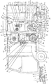
Refer to Fig. 1, provide chassis 1, the bottom of the left end on this chassis 1 is provided with a driven live axle 11 rotationally by driven live axle bearing (not shown), is respectively provided with a driven road wheel 111 at one end and the other end of this driven live axle 11.Bottom at the right-hand member on chassis 1 shows by positive transport wheel bearing support 122(Fig. 2) be provided with rotationally a positive transport wheel axle 12, be respectively provided with a positive transport wheel 121 at one end and the other end of this positive transport wheel axle 12.On chassis 1, be also provided with a distributing valve 13, a tank support 14 and a fan supporter 15, wherein: fan supporter 15 is positioned at the left side of tank support 14.
A headstock 2, a power drive mechanism 3, a fuel tank 4 and a garbage collection box 5 are provided, known as shown in Figure 1, headstock 2, power drive mechanism 3, fuel tank 4 and garbage collection box 5 are arranged in order (setting gradually) from the left end on chassis 1 to right-hand member, headstock 2 is essentially driver's cabin, is seated in headstock 2 and is manipulated by street cleaner (driver).Be also equipped with a storage tank 21 towards a side of power drive mechanism 3 at headstock 2 towards a side on the right side, power drive mechanism 3 is in transmission connection with aforesaid positive transport wheel axle 12, drives dust-absorption cleaning vehicle walking by power drive mechanism 3.Fuel tank 4 is arranged on the top of aforementioned tank support 14 with airborne, be provided with oil pump 41(Fig. 2 and indicate in this fuel tank 4), aforesaid distributing valve 13 is connected with oil pump 41 oil circuits, forms oil circuit by hydraulic oil pipeline with oil pump 41 and is connected.As preferred scheme, also can be fuel tank 4 and be equipped with an oil cooler 42.The motor 31(that aforesaid storage tank 21 both can be power drive mechanism 3 is generally diesel engine) supplement the water of cooling use, can be again in garbage collection box 5 every water tank 53 moisturizings of establishing.
Provide a dust collection mechanism 6, this dust collection mechanism 6 is arranged on chassis 1, more particularly be arranged on the top of aforementioned fan supporter 15, because dust collection mechanism 6 is arranged on the top of fan supporter 15, thereby shown the top corresponding to aforementioned power drive mechanism 3 with airborne, and be connected with aforesaid garbage collection box 5.
Provide pair of discs broom cleaning agency 7, this pair of discs broom cleaning agency 7 is connected to the corresponding both sides of the left end on aforementioned chassis 1 with the state corresponding to each other, state is known as shown in Figure 1, pair of discs broom cleaning agency 7, corresponding to the left side of a pair of driven road wheel 111, is positioned at the front of driven road wheel 111.
Provided a dedusting dolly 8, this dedusting dolly 8 is connected to the right-hand member on chassis 1, and is connected with the bottom of garbage collection box 5, communicate, and this garbage collection box chamber 51 communicates with aforesaid dust collection mechanism 6 with the garbage collection box chamber 51 of garbage collection box 5 simultaneously.
Please continue to refer to Fig. 1, technical essential as technical scheme provided by the invention: for the dust-absorption cleaning vehicle of aforementioned structure system has been equipped with a blower fan power transition transmission mechanism 9, this blower fan power transition transmission mechanism 9 is arranged on aforesaid fan supporter 15, and be positioned at substantially the middle part of the short transverse of fan supporter 15, corresponding to the top of power drive mechanism 3, by this blower fan power transition transmission mechanism 9, power drive mechanism 3 and dust collection mechanism 6 are formed each other to the relation that is in transmission connection or remove the relation that is in transmission connection between power drive mechanism 3 and dust collection mechanism 6.Hence one can see that, when dust-absorption cleaning vehicle is during in state to road-cleaning (dust-absorption cleaning vehicle is low advanced), by blower fan power transition transmission mechanism 9, power drive mechanism 3 and dust collection mechanism 6 are formed to the relation of being in transmission connection each other, in driving positive transport wheel axle 12 to move, drive drifting dust mechanism 6 to work by power drive mechanism 3, so configure power for dust collection mechanism 6 separately prior art without resembling, make power drive mechanism 3 bring into play the effect of working along both lines; When dust-absorption cleaning vehicle is during in transport condition to the non-cleaning of road, make the relation broken that is mutually in transmission connection between power drive mechanism 3 and dust collection mechanism 6 by blower fan power transition transmission mechanism 9, thereby embodied all sidedly the technique effect of recording in the superincumbent technique effect of applicant hurdle.
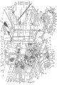
Refer to Fig. 2 and still in conjunction with Fig. 1, aforesaid power drive mechanism 3 preferably but not the structure being definitely limited to is as follows: comprise motor 31, engine spindle large drive wheel 32a, engine spindle brief biography driving wheel 32b, motor large drive wheel driving-belt 33a, motor brief biography driving wheel driving-belt 33b, gearbox 34, gearbox power input drive 35a, gearbox power output drive wheel 35b, gearbox power output drive wheel driving-belt 35c, transition power transmission shaft 36, transition power transmission shaft deceleration transmission wheel driving-belt 37, deceleration large drive wheel 38 and positive transport wheel through-drive wheel 39, motor 31 preferably uses Diesel engine, find a place for and be fixed on shortly on chassis 1 and corresponding to the below of aforementioned fan supporter 15, corresponding to the left side of aforementioned fuel tank 4, more precisely motor 31 is corresponding to the left side of tank support 14.Engine spindle large drive wheel 32a is fixed on one end (front end of location status shown in Fig. 1 and Fig. 2) of the engine spindle 311 of motor 31, and engine spindle brief biography driving wheel 32b is fixed on the other end (rear side of location status shown in Fig. 1 and Fig. 2) of engine spindle 311.One end of motor large drive wheel driving-belt 33a is nested with on engine spindle large drive wheel 32a, and the other end and aforesaid dust collection mechanism 6 are in transmission connection.One end of motor brief biography driving wheel driving-belt 33b is nested with on engine spindle brief biography driving wheel 32b, and the other end is nested with on gearbox power input drive 35a.Gearbox 34 is arranged on chassis 1, and corresponding to the below of aforesaid tank support 14.Gearbox power input drive 35a is fixed in the gearbox power input shaft (not shown) of gearbox 34, and gearbox power output drive wheel 35b is fixed on the speed changing box power output shaft 341 of gearbox 34.Transition power transmission shaft 36 is bearing in transition transmission shafts bearing 361 with level rotationally with horizontally-arranged state, and this transition transmission shafts bearing 361 is fixed on chassis 1, more precisely, this transition transmission shafts bearing 361 is fixed on aforesaid tank support 14 by seat board 3611.As shown in Figure 2, be that shown position is fixed with a transition transmission shaft driven wheel 362 towards front one end in one end of transition power transmission shaft 36, and the other end towards after one end be fixed with a transition power transmission shaft transition drive 363.One end of gearbox power output drive wheel driving-belt 35c is nested with on transition power transmission shaft transition drive 363, and the other end is nested with on gearbox power output drive wheel 35b.One end of transition power transmission shaft deceleration transmission wheel driving-belt 37 is nested with on transition transmission shaft driven wheel 362, and the other end is nested with on deceleration large drive wheel 38.Deceleration large drive wheel 38 is fixed on deceleration large drive wheel axle 382, and this deceleration large drive wheel axle 382 is bearing on deceleration large drive wheel axle bed 3821 rotationally with horizontal boom state, this deceleration large drive wheel axle bed 3821 is fixed on chassis 1, and deceleration large drive wheel 38 has a sub-drive 381, on this sub-drive 381, be equipped with one end of a sub-drive driving-belt 3811, and the other end of sub-drive driving-belt 3811 is nested with on positive transport wheel through-drive wheel 39, this positive transport wheel through-drive wheel 39 is preferably fixing with the fixing mode of flat key and positive transport wheel axle 12.On positive transport wheel through-drive wheel 39, be fixed with an axle sleeve 391, positive transport wheel 121 is connected with axle sleeve 391.As shown in Figure 2, axle sleeve 391 forms and has a drive adpting flange 3911 towards one end of positive transport wheel through-drive wheel 39, there is a road wheel adpting flange 3912 and form towards one end of positive transport wheel 121, drive adpting flange 3911 is fixing with positive transport wheel through-drive wheel 39, and road wheel adpting flange 3912 is fixing with the wheel hub 1211 of positive transport wheel 121.
In order to ensure tensioner or the title tension force of transition power transmission shaft deceleration transmission wheel driving-belt 37, therefore on aforementioned base 1, be provided with a straining pulley adjusting seat 17(position adjustable), in this straining pulley adjusting seat 17, arrange a straining pulley 171, make transition power transmission shaft deceleration transmission wheel driving-belt 37 in tensioner state by this straining pulley 171.
When road-sweeper is during in state to road-cleaning, make motor large drive wheel driving-belt 33a in tensioner (tightening) state by aforesaid blower fan power transition transmission mechanism 9, between motor large drive wheel driving-belt 33a and dust collection mechanism 6, form each other the relation that is in transmission connection, and drive dust collection mechanism 6 to work by motor large drive wheel driving-belt 33a, otherwise with example.
The course of work of aforementioned power drive mechanism 3 is as follows: by being positioned at street cleaner's (driver) the operation of headstock 2, make motor 31 in running order, engine spindle 311 rotates, drive the engine spindle large drive wheel 32a fixing with it and engine spindle brief biography driving wheel 32b by engine spindle 311 simultaneously, under the control of aforementioned blower fan power transition transmission mechanism 9, determine while whether driving dust collection mechanism 6(cleaning state by motor large drive wheel driving-belt 33a and drive, when non-cleaning state, do not drive).Drive gearbox power input drive 35a by motor brief biography driving wheel driving-belt 33b, power is caused to gearbox 34, drive gearbox power output drive wheel 35b by speed changing box power output shaft 341, drive transition power transmission shaft transition drive 363 by gearbox power output drive wheel 35b by gearbox power output drive wheel driving-belt 35c, drive transition transmission shaft driven wheel 362 through transition power transmission shaft 36, drive deceleration large drive wheel 38 by this transition transmission shaft driven wheel 362 by transition power transmission shaft deceleration transmission wheel driving-belt 37, be with mover drive 381 by deceleration large drive wheel 38, drive positive transport wheel through-drive wheel 39 by sub-drive 381 by sub-drive driving-belt 3811, drive positive transport wheel axle 12 by positive transport wheel through-drive wheel 39, thereby positive transport wheel 121 is moved.
In the present embodiment, described engine spindle large drive wheel 32a, engine spindle brief biography driving wheel 32b and gearbox power input drive 35a are belt pulley, aforesaid motor large drive wheel driving-belt 33a and motor brief biography driving wheel driving-belt 33b are driving belt, aforesaid gearbox power output drive wheel 35b, transition transmission shaft driven wheel 362, transition power transmission shaft transition drive 363, deceleration large drive wheel 38, sub-drive 381 and positive transport wheel through-drive wheel 39 are sprocket wheel, aforementioned gearbox power output drive wheel driving-belt 35c, sub-drive driving-belt 3811 and transition power transmission shaft deceleration transmission wheel driving-belt 37 are driving chain.
As shown in Figure 2, in the garbage collection box chamber 51 of aforementioned garbage collection box 5 and be positioned on the diapire in garbage collection box chamber 51 and be fixed with a garbage collection box interface 52, on garbage collection box interface 52, connect one for rubbish being imported to the rubbish ingress pipe 521 in garbage collection box chamber 51, aforesaid dustproof dolly 8 is connected with this garbage collection box interface 52 in the bottom corresponding to garbage collection box 5.
Continue to see Fig. 2 and continue in conjunction with Fig. 1, in the garbage collection box chamber 51 of aforesaid garbage collection box 5 every being provided with a water tank 53, in water tank 53, be provided with a water tank demarcation strip 531, the water tank roof of the upper end of this water tank demarcation strip 531 and water tank 53 is fixed, and stretch towards the below of water tank 53 with vertical cantilever state lower end, and the space between the tank bottom wall of the lower end of this water tank demarcation strip 531 and water tank 53 is configured to airway 534, wherein: the region that is positioned at the left side of water tank demarcation strip 531 is configured to dedusting tube chamber 532, and the region that is positioned at the right side of water tank demarcation strip 531 is configured to outlet chamber 533, between dedusting tube chamber 532 and outlet chamber 533, connected by aforesaid airway 534.In dedusting tube chamber 532, be provided with a dust removing tube 535, the dedusting tube chamber roof of the upper end of this dust removing tube 535 and dedusting tube chamber 532 is fixed, and stretch towards the below of dedusting tube chamber 532 with vertical cantilever state the lower end of dust removing tube 535 and the dust removing tube dust mouth 5351 of this dust removing tube 535 and be poured between the water surface of the water in water tank 53 and maintain spacing 5352.In the present embodiment, dust removing tube 535 is the pipe of internal diameter 12-16 ㎝, but also can use square tube, aforesaid spacing 5352 is 8-12 ㎝, be preferably 9-11 ㎝, be preferably 10 ㎝, the present embodiment is selected 10 ㎝, between the water surface in dust removing tube dust mouth 5351 and water tank 53, maintains the spacing 5352 of 10 ㎝.On the water tank roof of aforementioned water tank 53 and offering one corresponding to the position of outlet chamber 533 for the air in outlet chamber 533 being caused to extraneous outlet chamber gas outlet 536, be provided with blowoff valve 537 in the bottom of water tank 53, and on the left side wall of water tank 53, be provided with for water inlet interface 538 and the overflow pipe 539 to the interior introducing water of water tank 53, this overflow pipe 539 is positioned at into the below of water interface 538, also form and have one to cross dirt chamber 54 on the top in the garbage collection box chamber 51 of garbage collection box 5, cross between dirt chamber 54 and garbage collection box chamber 51 and be provided with screen pack 541 at this, and offer a dust mouth 542 in mistake dirt chamber 54 towards the crossing on the wall of dirt chamber of a side of aforementioned dust collection mechanism 6, dust collection mechanism 6 is simultaneously matched with dust mouth 542 and described dust removing tube 535.
According to common practise, aforesaid garbage collection box 5 is certainly equipped with a chamber door 55, and in the time closing chamber door 55, the sealing that this chamber door 55 is good with garbage collection box 5 chamber door interruption-formings, has illustrated in Fig. 1 that the situation that box door hinges 551 is connected with the chamber door mouth of garbage collection box 5 is passed through on the upper edge of chamber door 55.Preferred scheme also can be chamber door 55 and configures a pair of air spring cylinder 552, a pair of air spring cylinder 552 corresponds respectively to the both sides of chamber door 55, the chamber wall in the cylinder body of each air spring cylinder 552 and garbage collection box chamber 51 is hinged, and the air spring cylinder post of air spring cylinder 552 is connected with chamber door 55.Preferably, in the forward and backward side (location status shown in Fig. 2 is example) of garbage collection box 5 and at the marginal position corresponding to chamber door 55, chamber door tab 56 is respectively set, by chamber door tab 56, chamber door 55 is limited.
Under dust-absorption cleaning vehicle is in running order, and in the time of the state of dust collection mechanism 6 in being driven by power drive mechanism 3, pavement garbage is being mingled with trifle in the world and is entering in garbage collection box chamber 51 through garbage collection box interface 52 and rubbish ingress pipe 521 successively from dedusting dolly 8, under this state because dust collection mechanism 6 is in running order, thereby garbage collection box chamber 51 is interior in negative pressure state, rubbish on road is just able to enter garbage collection box chamber 51 through garbage collection box interface 52 and rubbish ingress pipe 521 successively from dedusting dolly 8, the dust inherent filtration net 541 entering in garbage collection box chamber 51 entered dirt chamber 54, the dust entering in dirt chamber 54 enters dust collection mechanism 6 from dust mouth 542, and the dust that comes from dust collection mechanism 6 sprays in the water in water tank 53 through the dust removing tube dust mouth 5351 of dust removing tube 535 under pressure, be mixed in the air effusion water surface in dust until drain into the external world from outlet chamber gas outlet 536, dust is trapped in water.In the time will getting rid of dirt in water tank 53, open blowoff valve 537, fill into by water inlet interface 538 when will be to water tank 53 moisturizing, moisturizing degree is limited with overflow pipe 539 spilling waters.Aforesaid storage tank 21 is taken from the water source of moisturizing.In said process, the relatively large rubbish of weight and/or volume is because meeting with stopping and relying on its deadweight productive set in garbage collection box chamber 51 of filter screen 541, when removing as long as open chamber door 55.
Still see Fig. 2 and in conjunction with Fig. 1, aforesaid dust collection mechanism 6 comprises dedusting fan 61, blower fan drive 62, blower fan sweep-up pipe 63 and blower fan dust outlet tube 64, dedusting fan 61 is fixed on the top of aforementioned fan supporter 15, the blower fan impeller shaft 611 of this dedusting fan 61 is bearing on fan supporter 15 rotationally by draught fan impeller bearing support 6111, blower fan drive 62 is fixed on blower fan impeller shaft 611, one end of blower fan sweep-up pipe 63 is connected with the dedusting fan air intake of dedusting fan 61, the other end is connected with aforementioned chamber, the dirt chamber wall of crossing of crossing dirt chamber 54 in the position corresponding to aforementioned dust mouth 542, and communicate with mistake dirt chamber 54, one end of blower fan dust outlet tube 64 is connected with the dedusting fan air outlet 612 of dedusting fan 6, the other end is stretched over described garbage collection box 5 and connects (communicating with the tube chamber of dust removing tube 535) with the upper end of aforementioned dust removing tube 535.The motor large drive wheel driving-belt 33a of aforementioned power drive mechanism 3 is nested with on blower fan drive 62, is arranged on blower fan power transition transmission mechanism 9 belows corresponding to described blower fan drive 62 at the middle part of the short transverse of aforementioned fan supporter 15.
According to the description to garbage collection box 5 and water tank 53 above applicant, in the time that dedusting fan 61 is worked, the dust of crossing in dirt chamber 54 enters blower fan sweep-up pipe 63 from dust mouth 542, enter dust removing tube 535 by dedusting fan air outlet 612 through blower fan dust outlet tube 64 again, by the dust removing tube dust mouth 5351 of dust removing tube 535, dust is sprayed in the water in water tank 53.
Aforesaid blower fan power transition transmission mechanism 9 comprises expansion tightening wheel adjusting seat 91, large drive wheel driving-belt expansion tightening wheel 92, adjust seat board holder 93, adjust seat board 94, adjust screw rod 95, the acting cylinder 96 of cranking arm, crank arm 97 and ferry-boat drive 98, expansion tightening wheel adjusting seat 91 is screwed on aforementioned fan supporter 15 and is positioned at the middle part of the short transverse of fan supporter 15, large drive wheel driving-belt expansion tightening wheel 92 is arranged on large drive wheel driving-belt tensioner wheel shaft 921 rotationally, and limited by the nut 9211 being disposed on driving-belt tensioner wheel shaft 921, large drive wheel driving-belt tensioner wheel shaft 921 is arranged in expansion tightening wheel adjusting seat 91, adjust that seat board holder 93 is fixed on fan supporter 15 and corresponding to the top of expansion tightening wheel adjusting seat 91, adjusting seat board 94 is connected on adjustment seat board holder 93, one end of adjusting screw rod 95 is threaded with adjustment seat board holder 93, the other end is fixedly connected with adjustment seat board 94, the acting cylinder 96 of cranking arm is connected to be adjusted on seat board 94, the acting cylinder post 961 of cranking arm of this acting cylinder 96 of cranking arm is towards cranking arm 97, this one end of 97 of cranking arm is hinged with the acting cylinder post 961 of cranking arm, crank arm 97 middle part is connected on fan supporter 15 by crank pin 971 pivotables, ferry-boat drive 98 is arranged on 97 the other end of cranking arm rotationally.Aforesaid large drive wheel driving-belt expansion tightening wheel 92 and swing drive 98 contact with aforementioned motor large drive wheel driving-belt 33a, and in the time that 97 the lower end of cranking arm swings to the right (while being rocked to right state), make motor large drive wheel driving-belt 33a in tensioned state by swinging drive 98, and drive described blower fan drive 62 by motor large drive wheel driving-belt 33a, and in the time that 97 the lower end of cranking arm swings left, make motor large drive wheel driving-belt 33a in relaxed state by swinging drive 98, motor large drive wheel driving-belt 33a does not drive blower fan drive 62.At motor large drive wheel driving-belt 33a, in the time tightening in tensioner state, aforesaid large drive wheel driving-belt expansion tightening wheel 92 makes motor large drive wheel driving-belt 33a in tensioner state simultaneously, and vice versa.
In the present embodiment, the aforesaid acting cylinder 96 of cranking arm, for oil cylinder, is connected with aforesaid distributing valve 13 hydraulic circuits; Aforesaid 97 the shape of cranking arm is 7 fonts.
In aforesaid expansion tightening wheel adjusting seat 91, offer an expansion tightening wheel axial adjustment groove 911, aforesaid large drive wheel driving-belt tensioner wheel shaft 921 is fixing in the position corresponding to expansion tightening wheel axial adjustment groove 911 and expansion tightening wheel adjusting seat 91; On aforesaid adjustment seat board 94, offer a pair of adjustment tank 941, adjust seat board 94 and be connected with aforementioned adjustment seat board holder 93 in the position corresponding to this pair of adjustment tank 941; Form at the end of the aforesaid acting cylinder post 961 of cranking arm the acting cylinder post connector 9611 of cranking arm, aforementioned 97 one end and this acting cylinder post connector 9611 of cranking arm of cranking arm is hinged.
As shown in Figure 2, the left end that is location status shown in Fig. 2 towards one end of adjusting screw rod 95 at aforesaid adjustment seat board 94 is preferably fixed with an acting cylinder Connection Block 942 with welding manner, and aforesaid adjustment screw rod 95 is connected with this acting cylinder Connection Block 942.Form and have the hinged ear 9421 of a pair of acting cylinder seat on the top of acting cylinder Connection Block 942, the aforesaid acting cylinder 96 of cranking arm is hinged with the hinged ear 9421 of this acting cylinder seat.
In the time will adjusting the position of large drive wheel driving-belt expansion tightening wheel 92, by large drive wheel driving-belt tensioner wheel shaft 921, the position on expansion tightening wheel axial adjustment groove 911 is adjusted.In the time the position of the acting cylinder 96 of cranking arm will being adjusted, as long as unscrew so for adjusting the seat board 94 adjustment seat board hold-down screw 943 fixing with adjusting seat board holder 93, the then mobile seat board 94 of adjusting, again adjustment seat board hold-down screw 943 is screwed, thereby the position of the acting cylinder 96 that makes to crank arm changes, the drive 98 that finally makes to ferry obtains the tension of expecting to motor large drive wheel driving-belt 33a.
Please see Fig. 2 by emphasis, aforesaid dedusting dolly 8 comprises dolly lift action cylinder 81, dolly body 82, dolly lift arm 83, lift arm connecting rod 84 and sweep-up pipe 85, dolly lift action cylinder 81 is fixed on tank support 14 with vertical cantilever state by acting cylinder Connection Block 821, the dolly lift action cylinder post 811 of this dolly lift action cylinder 81 towards under, dolly body 82 is connected with the end of dolly lift action cylinder post 811 by dolly lift action cylinder post engaging lug 826, corresponding both sides at the left end of this dolly body 82 are respectively provided with a traveling wheel of trolley 821 rotationally, and be provided with rotationally a dolly support roller 822(universal wheel in the middle position of the right-hand member of dolly), and in the both sides of dolly body 82 and the edge of right-hand member be provided with and enclose dirt curtain 823, this encloses dirt curtain 823 and also can be described as and enclose dirt shirt rim, dolly lift arm 83 has parallel a pair of, on the pivotally connected lift arm Connection Block 16 default on described chassis 1 of left end of this dolly lift arm 83, and right-hand member by bearing pin 831 with to be arranged on arm seat 825 on dolly body 82 hinged, lift arm connecting rod 84 has mutually walk abreast a pair of, one end of this lift arm connecting rod 84 and the One On The Chassis aforementioned lift arm Connection Block 16 are pivotally connected, and the other end is hinged by pivot 841 and dolly lift arm 83, one end of sweep-up pipe 85 and aforementioned garbage collection box interface 52 connect, the other end and sweep-up pipe joint 851 connect, and sweep-up pipe joint 851 is fixed on dolly body 82, wherein: dolly body 1 forms and has a dust-collecting cavity 824 towards a side of terrace under use state, aforementioned sweep-up pipe joint 851 communicates with dust-collecting cavity 824, and enclose the both sides of dirt curtain 823 to dust-collecting cavity 824 and the edge of right-hand member is sealed by aforementioned.
In the present embodiment, aforesaid dolly lift action cylinder 81 is oil cylinder, and is connected with aforesaid distributing valve 13 hydraulic circuits, and described encloses dirt curtain 823 for the door curtain made of cloth or rubber curtain.
When dust-absorption cleaning vehicle is during in non-cleaning state, the dolly lift action cylinder post 811 of dolly lift action cylinder 81 bounces back in cylinder body, drives dolly body 82 to top offset by it, otherwise with example.
Refer to Fig. 3 and in conjunction with Fig. 1, aforementioned pair of discs broom cleaning agency 7 respectively comprises disk broom fixed cross beam 71, strut socket 72, strut 73, disk broom lift action cylinder 74, extension spring 75, Inclination maneuver screw rod 76, hydraulic motor holder 77, hydraulic motor 78 and disk broom 79, disk broom fixed cross beam 71 is fixed on the left end on aforementioned chassis 1 by junction plate 713, on this disk broom fixed cross beam 71 and the end that is positioned at disk broom fixed cross beam 71 be fixed with an axis pin base 711 and a limiting plate 712 with welding manner, axis pin base 711 is corresponding with strut socket 72, limiting plate 712 is corresponding to the outside of axis pin base 711, and be equipped with one for the caging bolt 7121 spacing to strut socket 72 with heeling condition on this limiting plate 712, strut socket 72 is connected with axis pin base 711 pivotables by strut socket bearing pin 722, strut 73 offers strut pin shaft hole 732 towards one end of strut socket 72, with pin shaft hole screw 7321 by strut 73 towards one end of strut socket 72 hinged corresponding to the position and the strut socket 72 that are opened in the strut bearing pin mating holes 723 on strut socket 72, particularly, pin shaft hole screw 7321 is inserted to strut bearing pin mating holes 723 and strut pin shaft hole 732 successively, strut 73 is configured to cantilever end towards one end of disk broom 79, disk broom lift action cylinder 74 is connected corresponding to the top of strut 73 and with aforementioned distributing valve 13 hydraulic circuits, this disk broom lift action cylinder 74 by acting cylinder bearing pin screw 742 hinged corresponding to the position and the strut socket 72 that are opened in the pin shaft hole 724 on strut socket 72, and the end of the disk broom lift action cylinder post 741 of this disk broom lift action cylinder 74 is connected towards one end of disk broom 79 with strut 73, one end of extension spring 75 is fixed on the extension spring holder 771 on hydraulic motor holder 77, the other end is fixed on limiting plate 712 and offers on extension spring locating hole 7122, one end of Inclination maneuver screw rod 76 is connected with hydraulic motor holder 77, the other end is connected with strut socket 72, hydraulic motor holder 77 is hinged on strut 73 one end towards disk broom 79 by the hinged ear 772 of hydraulic motor holder and with hinged seat bearing pin 773, hydraulic motor 78 is fixed on hydraulic motor holder 77, and be connected with aforementioned distributing valve 13 hydraulic fluid roads, disk broom 79 is in transmission connection with hydraulic motor 78.
As shown in Figure 3, on aforesaid strut socket 72 and corresponding to aforementioned strut 73, the position below one end of strut socket 72 is equipped with a strut stop screw 721 with thread fiting mode, this strut stop screw 721 contacts with strut 73.Controlled by the degree that can make strut 73 upwards lift towards one end of disk broom 79 to regulating clockwise or counterclockwise of strut socket stop screw 721 or to dip down.
On the upper surface of one end of disk broom 79, be fixed with a pair of parallel cylinder post junction plate 731 at aforementioned strut 73, on this pair of cylinder post junction plate 731 and respectively offer a chute 7311 in position to correspond to each other, on chute 7311, be equipped with slidably a cylinder post connector sliding axle 73111, the end of the disk broom lift action cylinder post 741 of aforementioned disk broom lift action cylinder 74 forms a cylinder post connector 7411, and this cylinder post connector 7411 is connected with described cylinder post connector sliding axle 73111.
As shown in the above description, aforesaid disk broom lift action cylinder 74 is oil cylinder.When dust-absorption cleaning vehicle is during in non-cleaning state; the disk broom lift action cylinder post 741 of disk broom lift action cylinder 74 moves in cylinder body; thereby strut 73 is carried on one end of disk broom 79; make disk broom 79 leave terrace, travel and contribute to protect disk broom 79 in order to dust-absorption cleaning vehicle.In the time that disk broom clashes into for 79 rounds, for example, in the time clashing into the road tooth of road, just turned round towards the direction that deviates from road tooth together with strut 73 by strut socket 72, and then drive disk broom 79 to move towards deviating from road tooth direction by strut 73, avoid disk broom 79 to occur suffering road tooth damage phenomenon simultaneously.The return of disk broom 79 ensures by extension spring 75, and spacing to the side of strut socket 72 by caging bolt 7121.Avoid disk broom 79 to damage.The function of aforesaid Inclination maneuver screw rod 76 is the Inclination maneuvers to disk broom 79.
If the position of (shown position state is example) arranges a pair of structure and the identical but specification of pair of discs broom cleaning agency 7 and is slightly less than the auxiliary cleaning agency of disk broom of pair of discs broom cleaning agency 7 again at the right-hand member on chassis 1 and in the left side corresponding to dedusting dolly 8, to road garbage is further collected to centre by the auxiliary cleaning agency of this pair of discs broom, is so more conducive to embody the dust removing effects of dedusting dolly 8.
Applicant sketches use of the present invention, at dust-absorption cleaning vehicle during in cleaning state to road, by the cleaner in headstock 2 by the operation that is arranged on the control system in headstock 2, motor 31 is worked, main, driven road wheel 111, 121 in travel condition low, simultaneously by the operation to control system, the acting cylinder 96 of cranking arm of blower fan power transition transmission mechanism 9 is worked, the acting cylinder post 961 of cranking arm bounces back in cylinder body, drive and crank arm 97 by the acting cylinder post 961 of cranking arm, make to crank arm 97 upper end to left dislocation, and 97 the lower end side of cranking arm swings to the right, because ferry-boat drive 98 is arranged on 97 the lower end of cranking arm rotationally, therefore in the time that 97 the lower end of cranking arm swings to the right, drive ferry-boat drive 98 to swing to the right, make to ferry drive 98 and power drive mechanism 3 motor large drive wheel driving-belt 33a near, that is to say by ferry-boat drive 98 makes the previous motor large drive wheel driving-belt 33a in relaxed state in tensioner state, thereby driven the blower fan drive 62 of dust collection mechanism 6 by motor large drive wheel driving-belt 33a, make dedusting fan 61 in running order.Simultaneously, pair of discs broom cleaning agency 7 is also in running order, rubbish on road is driven towards the central region on chassis 1, sweep to the central region on chassis 1, because vehicle is in transport condition low, therefore by the sweep-up pipe 85 of dedusting dolly 8, rubbish is introduced in garbage collection box chamber 51, because under the work of dust collection mechanism 6, garbage collection box chamber 51 is in negative pressure state, enters into rubbish in garbage collection box chamber 51 by applicant's description processing to garbage collection box 5 and dust collection mechanism 6 in the above.
During when cleaning end and in transport condition, make aforementioned acting cylinder 96 reverse operations of cranking arm, ferry-boat drive 98 is to left dislocation, make motor large drive wheel driving-belt 33a in relaxed state, power transmission relation broken between power drive mechanism 3 and dust collection mechanism 6, and under the work of dolly lift action cylinder 81, make dolly body 82 up and leave terrace, and make to carry on disk broom 79 under the work of the disk broom lift action cylinder 74 of disk broom cleaning agency 7, specifically: disk broom lift action cylinder post 741 bounces back (when cleaning state in cylinder body, disk broom lift action cylinder post 741 stretches out outside cylinder body).
In sum, technical scheme provided by the invention has overcome the shortcoming in prior art, has completed invention task, has embodied objectively the technique effect referring in the superincumbent technique effect of applicant hurdle, and can yet be regarded as is a ultimate attainment technical scheme.