CN103759517A - Multichannel vertical dryer - Google Patents
Multichannel vertical dryer Download PDFInfo
- Publication number
- CN103759517A CN103759517A CN201410004251.7A CN201410004251A CN103759517A CN 103759517 A CN103759517 A CN 103759517A CN 201410004251 A CN201410004251 A CN 201410004251A CN 103759517 A CN103759517 A CN 103759517A
- Authority
- CN
- China
- Prior art keywords
- discharge
- cylinder body
- multichannel
- air inlet
- outer cylinder
- Prior art date
- Legal status (The legal status is an assumption and is not a legal conclusion. Google has not performed a legal analysis and makes no representation as to the accuracy of the status listed.)
- Pending
Links
Images

Abstract
The invention provides a multichannel vertical dryer which comprises a feed bin, a distribution cone, a drying cylinder and a discharge hopper. A plurality of region division plates are arranged between an inner cylinder and an outer cylinder to divide a material channel into a plurality of regions. The discharge hopper is of a double-layer cone structure. Material separation plates are arranged in the cone to divide the discharge hopper into a plurality of discharge regions. Each discharge region is provided with a discharge gate. Through the region division plates, the material separation plates and the discharge gates, a plurality of independent drying channels are formed, and each channel can control drying of a part of materials individually. Once the materials are on fire, the discharge gates are operated to discharge to-be-fired materials rapidly, so that burning of materials in the whole drying cylinder can be avoided, and fire-caused equipment damage and production loss can be reduced.
Description
Technical field
The present invention relates to a kind of drying plant, especially a kind of dryer of drying graininess combustible material.
Background technology
In industrial production, dry at present the large-scale drying plant of granular material conventional have rotary drying machine and a tower drier, wherein tower drier has advantages of that occupied ground area is little, drying efficiency is high, small investment, in market, obtains a wide range of applications.
Tower drier is by external heat source or the combustion furnace hot wind supply that carries, material to be dried is risen to the appearance hopper at dryer top by material elevator, under self gravitation effect, material falls, by material distributing cone by material dispersion, form material bed that a tubular falls, hot blast is forced to see through material bed lateral flow under draw at air-introduced machine, carries out heat exchange with material, add after steam that thermal material produces and waste gas are gathered dust by exhaust apparatus and discharge, reach the object of material drying.
The hot blast of tower drier is introduced from Drying bottom, for improving productive rate and utilization efficiency of heat energy, need to adopt high as far as possible hot blast temperature, yet for drying flammable material ratio as blue charcoal, temperature height easily causes that Drying bottom material catches fire, and once somewhere material catches fire, ignition point can bamboo telegraph arrive other region, causes material burning in whole Drying, brings huge loss to equipment and production.
Summary of the invention
The object of the invention is to overcome the problems referred to above that existing dryer exists, a kind of multichannel tower drier that stops ignition point diffusion is provided.
Multichannel tower drier provided by the invention, comprise feeding warehouse, material distributing cone, drying cylinder body, discharge bucket, described drying cylinder body comprises inner barrel and outer cylinder body, on inner barrel and outer cylinder body, have air port, between inner barrel and outer cylinder body, be provided with inside and outside collet, the position, gap of inside and outside collet forms annular materials passage, and the outer setting of outer cylinder body has air intake cylinder and exhaust tube, it is characterized in that: between described inner barrel and outer cylinder body, be provided with a plurality of subregion plates, material channel is divided into a plurality of districts; Described discharge bucket is double-deck cone barrel structure, in cone cylinder, material baffle is set, and discharge bucket is divided into a plurality of discharge zones; Described each discharge zone arranges discharge gate.
Tower drier of the present invention is provided with a plurality of subregion plates between inner barrel and outer cylinder body, annular materials passage has been divided into a plurality of districts, the material baffle arranging in discharge bucket is bored barrel structure by bilayer and has been divided into a plurality of discharge zones, coordinate again discharge gate, formed a plurality of independently drying channels, each passage can be controlled separately the oven dry of a part of material.In work, if certain region material catches fire, isolation due to subregion plate, ignition point can bamboo telegraph not arrive other region, discharge gate by operational correspondence is discharged the material catching fire fast, can avoid the burning of material in whole Drying, reduce the loss of catching fire to the infringement of equipment and production.
Preferably, described subregion plate distributes along even circumferential.
Preferably, described air intake cylinder and exhaust tube are the cylindrical shell that is looped around outer cylinder body outside.
Preferably, the sidewall of described exhaust tube is provided with exhaust outlet, and the sidewall of described air intake cylinder is provided with air inlet.
Preferably, described air inlet is axially provided with two along air intake cylinder, and top is high temperature air inlet, and bottom is low temperature air inlet.
Preferably, between high temperature air inlet and low temperature air inlet, be provided with partition, for isolated gas, directly circulate.
Preferably, each district of described material channel is provided with temperature thermocouple.
Accompanying drawing explanation
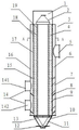
Fig. 1 is structural representation of the present invention.
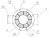
Fig. 2 is that Fig. 1 is at the cutaway view of A-A direction.
Fig. 3 is the top view of discharge bucket in Fig. 1.
The specific embodiment
Below in conjunction with drawings and Examples, the present invention is described in detail.
As shown in Figure 1, tower drier of the present invention comprises feeding warehouse 1, material distributing cone 2, drying cylinder body 3, discharge bucket 11, material promotes in the feeding warehouse 1(accompanying drawing that enters sealing and does not show elevator through elevator), it is material bed that material distributing cone 2 in feeding warehouse 1 circularizes shape by material dispersion, the annulation bed of material enters drying cylinder body 3 under Action of Gravity Field, material discharging from discharge bucket 11 after drying.
As shown in Figure 1 and Figure 2, drying cylinder body 3 comprises inner barrel 19 and outer cylinder body 17, on inner barrel 19 and outer cylinder body 17, has air port, is provided with inside and outside collet 18 between inner barrel 19 and outer cylinder body 17, and the position, gap of inside and outside collet 18 forms annular materials passage 4.Between inner barrel 19 and outer cylinder body 17, be provided with a plurality of subregion plates 20, subregion plate 20 is radial arrangement, on circumference, be uniformly distributed, the both sides of subregion plate 20 are connected with outer cylinder body 17 with inner barrel 19 respectively, the upper and lower side of subregion plate 20 connects the whole height of drying cylinder body 3, thereby subregion plate 20 is divided into a plurality of districts by annular materials passage 4.As shown in Figure 1, Figure 3, what discharge bucket 11 was that outer cone cylinder 10 and internal layer cone cylinder 13 form is double-deck cone barrel structure, material is discharged from the sandwich passage 21 of skin cone cylinder 10 and internal layer cone cylinder 13, the material baffle 22 that is radially provided with a plurality of inclinations in sandwich passage 21, material baffle 22 is divided into a plurality of discharge zones by sandwich passage 21.At the sidewall of discharge bucket 11, each discharge zone is provided with discharge gate 12, and discharge gate 12 extend into internal layer cone cylinder 13 from skin cone cylinder 10, through sandwich passage 21.Discharge gate 12 is driven by hydraulic cylinder or pneumatic cylinder, and along the radial motion of discharge bucket 11, the size that each discharge zone passage is opened is carried out independent control in the horizontal direction.
The outer setting of outer cylinder body 17 has air intake cylinder 7 and exhaust tube 6, in preferred version, air intake cylinder 7 and exhaust tube 6 are the circular cylinder around outer cylinder body 17, air intake cylinder 7 is arranged on top, exhaust tube 6 is arranged on bottom, between air intake cylinder 7 and exhaust tube 6, be provided with annular partition panel 15, the isolated hot blast of partition panel 15 is directly circulation up and down between air intake cylinder 7 and exhaust tube 6.Air intake cylinder 7 and exhaust tube 6 have adopted the circular cylinder structure around outer cylinder body 17, in air intake district, hot blast can radially evenly flow at the whole circumferencial direction of outer cylinder body 17, in exhaust zone, hot blast can radially evenly be discharged at the whole circumferencial direction of outer cylinder body 17, thereby cloth wind is even, avoided hot blast concentration of local, further reduced the risk that material catches fire because of hot-spot.
In preferred version, be provided with vertically two-layer air inlet on air intake cylinder 7, upper strata is high temperature air inlet 141, and lower floor is low temperature air inlet 142.The hot blast of high temperature air inlet 141 input higher temperatures, at this drying section, temperature of charge is lower and contain more moisture, adopts the hot-air seasoning of higher temperature can improve drying efficiency and utilization efficiency of heat energy; The hot blast of low temperature air inlet 142 input lower temperatures, at this drying section, material through before heating had higher temperature and moisture lower, adopt the hot blast of lower temperature can avoid temperature of charge too high and catch fire, guarantee safety in production.Further in preferred version, between the high temperature air inlet 1411 of air intake cylinder 7 and low temperature air inlet 142, be provided with annular partition panel 8, partition panel 8 stops high-temperature hot-airs and low temperature hot blast in the interior directly circulation up and down of air intake cylinder 7.
For ease of monitoring in real time temperature of charge in Drying, in each subregion of annular materials passage 4, sensor for measuring temperature is installed, adopt thermocouple 9 to measure temperature, Multi-layer thermal galvanic couple 9 is installed in each region.Reserved corresponding duct in equipment preparation process, during installation, thermocouple 9 inserts from the outer wall of air intake cylinder 7, through outer cylinder body 17 and collet 18, enters material channel 4.
Above-described embodiment and accompanying drawing are nonrestrictive description; be intended to illustrate structural principle of the present invention; should be appreciated that, under the condition that does not depart from connotation of the present invention, apparatus of the present invention are made any be equal to or similar substitute, modification or revise is all included in the protection domain of the claims in the present invention book.
Claims (7)
1. a multichannel tower drier, comprise feeding warehouse, material distributing cone, drying cylinder body, discharge bucket, described drying cylinder body comprises inner barrel and outer cylinder body, on inner barrel and outer cylinder body, have air port, between inner barrel and outer cylinder body, be provided with inside and outside collet, the position, gap of inside and outside collet forms annular materials passage, and the outer setting of outer cylinder body has air intake cylinder and exhaust tube, it is characterized in that: between described inner barrel and outer cylinder body, be provided with a plurality of subregion plates, material channel is divided into a plurality of districts; Described discharge bucket is double-deck cone barrel structure, in cone cylinder, material baffle is set, and discharge bucket is divided into a plurality of discharge zones; Described each discharge zone arranges discharge gate.
2. multichannel tower drier according to claim 1, is characterized in that: described subregion plate distributes along even circumferential.
3. multichannel tower drier according to claim 2, is characterized in that: described air intake cylinder and exhaust tube are the cylindrical shell that is looped around outer cylinder body outside.
4. multichannel tower drier according to claim 3, is characterized in that: the sidewall of described exhaust tube is provided with exhaust outlet, and the sidewall of described air intake cylinder is provided with air inlet.
5. multichannel tower drier according to claim 4, is characterized in that: described air inlet is axially provided with two along air intake cylinder, and top is high temperature air inlet, and bottom is low temperature air inlet.
6. multichannel tower drier according to claim 5, is characterized in that: between high temperature air inlet and low temperature air inlet, be provided with partition, for isolated gas, directly circulate.
7. according to the multichannel tower drier described in claim 1-6 any one, it is characterized in that: each district of described material channel is provided with temperature thermocouple.
Priority Applications (1)
| Application Number | Priority Date | Filing Date | Title |
|---|---|---|---|
| CN201410004251.7A CN103759517A (en) | 2014-01-06 | 2014-01-06 | Multichannel vertical dryer |
Applications Claiming Priority (1)
| Application Number | Priority Date | Filing Date | Title |
|---|---|---|---|
| CN201410004251.7A CN103759517A (en) | 2014-01-06 | 2014-01-06 | Multichannel vertical dryer |
Publications (1)
| Publication Number | Publication Date |
|---|---|
| CN103759517A true CN103759517A (en) | 2014-04-30 |
Family
ID=50526793
Family Applications (1)
| Application Number | Title | Priority Date | Filing Date |
|---|---|---|---|
| CN201410004251.7A Pending CN103759517A (en) | 2014-01-06 | 2014-01-06 | Multichannel vertical dryer |
Country Status (1)
| Country | Link |
|---|---|
| CN (1) | CN103759517A (en) |
Cited By (3)
| Publication number | Priority date | Publication date | Assignee | Title |
|---|---|---|---|---|
| CN105758152A (en) * | 2016-04-27 | 2016-07-13 | 河南佰衡节能科技股份有限公司 | High temperature air source heat pump vertical dryer |
| CN112414093A (en) * | 2020-10-23 | 2021-02-26 | 安徽公牛农业发展有限公司 | Perpendicular drying tower of rice |
| CN115615175A (en) * | 2022-10-10 | 2023-01-17 | 喜科金属(昆山)有限公司 | Drying equipment for electrophoresis residues |
Citations (8)
| Publication number | Priority date | Publication date | Assignee | Title |
|---|---|---|---|---|
| US3474903A (en) * | 1968-10-22 | 1969-10-28 | Harry S Ausherman | Grain drying and debris separation device |
| CN1253066A (en) * | 1998-10-28 | 2000-05-17 | 株式会社松井制作所 | Vacuum dehumidifying and drying equipment |
| US6405454B1 (en) * | 1998-09-04 | 2002-06-18 | Motan Holding Gmbh | Method and apparatus for heating and/or drying flowable loose material |
| CN202470676U (en) * | 2012-03-07 | 2012-10-03 | 李成勇 | Carbon material drying machine |
| US8356420B2 (en) * | 2009-03-09 | 2013-01-22 | The Gsi Group, Llc | Adjustable divider/hopper for a grain tower dryer |
| CN202719851U (en) * | 2012-08-07 | 2013-02-06 | 陈学金 | Multi-point-blanking drying tower |
| CN103471362A (en) * | 2013-08-30 | 2013-12-25 | 河南省德耀节能科技有限公司 | Vertical single-channel material turnover dryer |
| CN203657402U (en) * | 2014-01-06 | 2014-06-18 | 新乡仲德能源科技有限公司 | Multichannel vertical drying machine |
-
2014
- 2014-01-06 CN CN201410004251.7A patent/CN103759517A/en active Pending
Patent Citations (8)
| Publication number | Priority date | Publication date | Assignee | Title |
|---|---|---|---|---|
| US3474903A (en) * | 1968-10-22 | 1969-10-28 | Harry S Ausherman | Grain drying and debris separation device |
| US6405454B1 (en) * | 1998-09-04 | 2002-06-18 | Motan Holding Gmbh | Method and apparatus for heating and/or drying flowable loose material |
| CN1253066A (en) * | 1998-10-28 | 2000-05-17 | 株式会社松井制作所 | Vacuum dehumidifying and drying equipment |
| US8356420B2 (en) * | 2009-03-09 | 2013-01-22 | The Gsi Group, Llc | Adjustable divider/hopper for a grain tower dryer |
| CN202470676U (en) * | 2012-03-07 | 2012-10-03 | 李成勇 | Carbon material drying machine |
| CN202719851U (en) * | 2012-08-07 | 2013-02-06 | 陈学金 | Multi-point-blanking drying tower |
| CN103471362A (en) * | 2013-08-30 | 2013-12-25 | 河南省德耀节能科技有限公司 | Vertical single-channel material turnover dryer |
| CN203657402U (en) * | 2014-01-06 | 2014-06-18 | 新乡仲德能源科技有限公司 | Multichannel vertical drying machine |
Cited By (5)
| Publication number | Priority date | Publication date | Assignee | Title |
|---|---|---|---|---|
| CN105758152A (en) * | 2016-04-27 | 2016-07-13 | 河南佰衡节能科技股份有限公司 | High temperature air source heat pump vertical dryer |
| CN105758152B (en) * | 2016-04-27 | 2017-12-15 | 河南佰衡节能科技股份有限公司 | Temperature air-source heat pump tower drier |
| CN112414093A (en) * | 2020-10-23 | 2021-02-26 | 安徽公牛农业发展有限公司 | Perpendicular drying tower of rice |
| CN115615175A (en) * | 2022-10-10 | 2023-01-17 | 喜科金属(昆山)有限公司 | Drying equipment for electrophoresis residues |
| CN115615175B (en) * | 2022-10-10 | 2023-10-20 | 喜科金属(昆山)有限公司 | Drying equipment of electrophoresis residue |
Similar Documents
| Publication | Publication Date | Title |
|---|---|---|
| CN103759516A (en) | Vertical drying machine uniform in air distribution | |
| JP3206741U (en) | Circulating grain dryer | |
| CN205907317U (en) | A locellus cooling device for sintering deposit, pellet | |
| CN103759517A (en) | Multichannel vertical dryer | |
| CN102230726B (en) | Sleeve type continuous calcining vertical kiln | |
| CN205328937U (en) | Novel living beings thermal cracking device | |
| CN104477915A (en) | Device for heating or drying materials and calcium carbide production equipment | |
| CN203657402U (en) | Multichannel vertical drying machine | |
| CN105841469A (en) | Gradient drying device for pine nuts | |
| CN205825665U (en) | Combined vertical carbon material dehydrator | |
| CN206222863U (en) | A kind of new wood dust dryer | |
| CN203657398U (en) | Uniform air distribution type vertical dryer | |
| CN202470676U (en) | Carbon material drying machine | |
| CN206085301U (en) | Pelletization device in gyration drying kiln kiln | |
| CN203464631U (en) | Drying device for wet felt | |
| CN203657397U (en) | Drainable vertical dryer | |
| CN204251343U (en) | The heating of material or drying unit and calcium carbide production unit | |
| CN203203361U (en) | Vertical drying machine for granular materials | |
| CN203657400U (en) | Peristaltic feeding vertical dryer | |
| CN103759515A (en) | Novel vertical dryer | |
| CN203657396U (en) | Novel vertical dryer | |
| CN211451767U (en) | High-temperature flue gas indirect heating type material storage and feeding device | |
| CN205784431U (en) | Semen Pini gradient drying unit | |
| CN102003869B (en) | Vertical double-cylinder drier | |
| CN202041059U (en) | Vertical type double-tube dryer |
Legal Events
| Date | Code | Title | Description |
|---|---|---|---|
| C06 | Publication | ||
| PB01 | Publication | ||
| C10 | Entry into substantive examination | ||
| SE01 | Entry into force of request for substantive examination | ||
| C02 | Deemed withdrawal of patent application after publication (patent law 2001) | ||
| WD01 | Invention patent application deemed withdrawn after publication |
Application publication date: 20140430 |