CN103758118A - Pile connecting structure and pile - Google Patents
Pile connecting structure and pile Download PDFInfo
- Publication number
- CN103758118A CN103758118A CN201410017104.3A CN201410017104A CN103758118A CN 103758118 A CN103758118 A CN 103758118A CN 201410017104 A CN201410017104 A CN 201410017104A CN 103758118 A CN103758118 A CN 103758118A
- Authority
- CN
- China
- Prior art keywords
- end plate
- hoop part
- groove
- syndeton
- segmentation
- Prior art date
- Legal status (The legal status is an assumption and is not a legal conclusion. Google has not performed a legal analysis and makes no representation as to the accuracy of the status listed.)
- Pending
Links
Images


Abstract
The invention discloses a pile connecting structure and a pile which comprise a first end plate and a second end plate connected by an outer hoop piece and an end face. The outer side surface of the first end plate forms a mounting surface with the outer side surface of the second end plate. Inner hoop pieces used for tightly hooping the first end plate and the second end plate are arranged on the mounting surface. The first end plate, the second end plate and the inner hoop pieces form a clamping piece. A first slot is arranged on the outer hoop piece, the clamping piece clamps in the first slot. The pile connecting structure and the pile is strong in anti-shearing, anti-drawing, anti-bending and anti-corrosive capacity, and is capable of reducing using times of electrowelding machines, reducing technical requirement on construction workers and labor intensity of workers.
Description
Technical field
The present invention relates to building unit technical field, particularly relate to a kind of syndeton and stake.
Background technology
Present stake syndeton is on the market generally that the mode by welding couples together upper head plate and bottom plate.This mode that upper head plate and bottom plate are welded to connect is anti-shearing, anti-pulling, bend resistance ability, because outside exposed, weld is easily corroded simultaneously.Moreover, be welded to connect construction workman's technical requirements high, the workman's that simultaneously needs to construct high labour intensity work, production efficiency is low.
Summary of the invention
Based on this, be necessary for prior art defect, provide a kind of anti-shearing, anti-pulling, bend resistance ability and resistance to corrosion strong, reduce the technical requirements of using electric welding, reducing construction workman simultaneously and reduce labor strength stake syndeton and.
Its technical scheme is as follows.
A kind of syndeton, comprise the first end plate, the second end plate that outer hoop part and end face join, the lateral surface of the lateral surface of this first end plate and the second end plate forms installed surface, on this installed surface, be provided with the interior hoop part that the first end plate, the second end plate is carried out to lock ring, the first end plate, the second end plate and interior hoop part form fastener; This outer hoop part is provided with the first draw-in groove, and described fastener is arranged in described the first draw-in groove.The technical program stake syndeton is carried out lock ring by sheathed interior hoop part on installed surface to the first end plate and the second end plate, strengthens the shear resistance of stake syndeton; Simultaneously, in the inner side of outer hoop part, the first draw-in groove is set, outer hoop part is arranged in interior hoop part, the first end plate and the formed fastener of the second end plate in its first draw-in groove, make its resistance to corrosion strong, further, owing to adopting mechanical connection to replace welding traditionally, reduce construction workman's technical requirements and reduce labor strength.
In an embodiment, in described the first draw-in groove, be provided with the second draw-in groove therein, described interior hoop part is arranged in described the second draw-in groove.
In an embodiment, described outer hoop part is provided with the first connecting hole therein, and described interior hoop part is provided with second connecting hole corresponding with the first connecting hole, and described the first connecting hole, the second connecting hole are threaded connection or pass through rivet.Outer hoop part and interior hoop part are threaded connection or rivet mutual locking the first end plate and the second end plate are carried out to lock ring, strengthen anti-shearing, anti-pulling, the bend resistance ability of stake syndeton.
Therein in an embodiment, described interior hoop part comprises at least two and binds round part segmentation to have the first connector between adjacent interior hoop part segmentation.Interior hoop part, for segmented designs, has at least two and binds round part segmentation, interior hoop part subsection setup, anti-pulling, the bend resistance ability of enhancing stake syndeton in convenient installation.
In an embodiment, described outer hoop part comprises the segmentation of at least two outer hoop parts therein, between adjacent outer hoop part segmentation, has the second connector, and described the first connector and the second connector stagger mutually, and the segmentation of described outer hoop part covers described the first connector.Outer hoop part, for segmented designs, has the segmentation of at least two outer hoop parts, outer hoop part subsection setup, the shear ability of enhancing stake syndeton in convenient installation.Meanwhile, the first connector and the second connector stagger mutually, and the segmentation of outer hoop part covers the first connector, in the bulk strength that strengthens stake syndeton, strengthen its anti-corrosion capability.
In an embodiment, the segmentation of described interior hoop part is provided with spacer pin near one end of the first connector therein, and described outer hoop part is provided with the limit pin hole matching with this spacer pin, and spacer pin is undertaken fastening through limit pin hole by adjacent interior hoop part segmentation.Adjacent interior hoop part segmentation is all provided with spacer pin in the one end near the first connector, and spacer pin carries out adjacent interior hoop part segmentation through limit pin hole fastening, makes it have blunt good integraty.
Therein in an embodiment, with the first end plate and the second end plate mutually close one end for the end that joins, the outer of the end that joins of described the first end plate arranges the first groove, and the outer of the end that joins of described the second end plate arranges the second groove, and described the first groove, the second groove welding connect.The first end plate and the second end plate first weld in the outer of its phase contact surface, carry out lock ring more afterwards by interior hoop part and outer hoop part, when not only having used mechanical connection but also use and be welded to connect, form insurance, improve the safety factor of stake syndeton.
The technical program also provides a kind of stake, comprise at least two end to end piles, first pile is connected with second pile by stake syndeton, described stake syndeton comprises the first end plate, the second end plate that outer hoop part and end face join, the lateral surface of the lateral surface of this first end plate and the second end plate forms installed surface, on this installed surface, be provided with the interior hoop part that the first end plate, the second end plate is carried out to lock ring, the first end plate, the second end plate and interior hoop part form fastener; This outer hoop part is provided with the first draw-in groove, and described fastener is arranged in described the first draw-in groove.The stake syndeton of the technical program stake is carried out lock ring by sheathed interior hoop part on installed surface to the first end plate and the second end plate, strengthens the shear resistance of stake syndeton; Simultaneously, in the inner side of outer hoop part, the first draw-in groove is set, outer hoop part is arranged in interior hoop part, the first end plate and the formed fastener of the second end plate in its first draw-in groove, make its resistance to corrosion strong, further, owing to adopting mechanical connection to replace welding traditionally, reduce construction workman's technical requirements and reduce labor strength.
In an embodiment, described the first end plate and first pile are formed in one therein, and described the second end plate and second pile are formed in one.Meanwhile, interior hoop part and the shape of outer hoop part and the cross section of pile match, and make the technical program stake syndeton be suitable for any preformed pile with end plate, comprise prestressed concrete pipe pile, pre-stressed concrete hollow square stake and concrete solid square pile etc.
Below the advantage of the technical program or principle are described.
The technical program stake syndeton is carried out lock ring by sheathed interior hoop part on installed surface to the first end plate and the second end plate, strengthens the shear resistance of stake syndeton; Simultaneously, in the inner side of outer hoop part, the first draw-in groove is set, outer hoop part is arranged in interior hoop part, the first end plate and the formed fastener of the second end plate in its first draw-in groove, make its resistance to corrosion strong, further, owing to adopting mechanical connection to replace welding traditionally, reduce construction workman's technical requirements and reduce labor strength.
Accompanying drawing explanation
Fig. 1 is the STRUCTURE DECOMPOSITION view of stake syndeton described in the invention process;
Fig. 2 is the structural representation of stake syndeton described in the invention process;
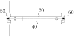
Fig. 3 is the structural representation of the first end plate and the second end plate described in the embodiment of the present invention;
Description of reference numerals:
10, first pile, the 20, first end plate, the 210, first groove, 30, second piles, the 40, second end plate, the 410, second groove, 50, outer hoop part, the 510, first draw-in groove, 520, the segmentation of outer hoop part, 60, interior hoop part, 70, installed surface.
The specific embodiment
Below in conjunction with accompanying drawing, the embodiment of the present invention is described in detail.
Please refer to Fig. 1 to 2.Stake syndeton is arranged between adjacent pile, by the stake of using in the end to end formation engineering construction of multistage pile.Stake syndeton comprises the first end plate 20, the second end plate 40 that interior hoop part 60, outer hoop part 50 and end face join.The first end plate 20 is formed in one with first pile 10, the second end plate 40 and second pile 30 are also formed in one, interior hoop part 60, outer hoop part 50, the first end plate 20 and second shape of end plate 40 and the cross section of pile match, make a syndeton be suitable for any preformed pile with end plate, comprise prestressed concrete pipe pile, pre-stressed concrete hollow square stake and concrete solid square pile etc.
The lateral surface of the lateral surface of this first end plate 20 and the second end plate 40 forms installed surface 70, is provided with interior hoop part 60, the first end plates 20, the second end plate 40 and the interior hoop part 60 formation fasteners that the first end plate 20, the second end plate 40 are carried out to lock ring on this installed surface 70; This outer hoop part 50 is provided with the first draw-in groove 510, and described fastener is arranged in described the first draw-in groove 510.Described outer hoop part 50 is provided with the first connecting hole, and described interior hoop part 60 is provided with second connecting hole corresponding with the first connecting hole, and described the first connecting hole, the second connecting hole are threaded connection or pass through rivet.Certainly, between interior hoop part 60 and installed surface 70, also can be nested cooperation, both are interference fit or matched in clearance its, at this moment all do not arrange on its both porose.In other embodiments, in described the first draw-in groove 510, be provided with the second draw-in groove, described interior hoop part 60 is arranged in described the second draw-in groove.
Wherein, described interior hoop part 60 comprises at least two and binds round part segmentation to have the first connector between adjacent interior hoop part segmentation.Described outer hoop part 50 comprises at least two outer hoop parts segmentation 520, between adjacent outer hoop part segmentation 520, has the second connector, and described the first connector and the second connector stagger mutually, and described outer hoop part segmentation 520 covers described the first connector.Interior hoop part 60 and outer hoop part 50 all can be integral type design or segmented design.When outer hoop part 50 is integral design, on outer hoop part 50, opening can be set, when hoop part 60 is taked segmented design at this moment, the first connector between the segmentation of interior hoop part need with outer hoop part 50 on opening stagger.Interior hoop part 60 and outer hoop part 50 all can adopt equal portions segmentation or not equal portions segmentation.The first connector, the second connector and opening can be taked to be welded to connect, to increase safety factor.
The segmentation of described interior hoop part is provided with spacer pin near one end of the first connector, and described outer hoop part 50 is provided with the limit pin hole matching with this spacer pin, and spacer pin is undertaken fastening through limit pin hole by adjacent interior hoop part segmentation.Interior hoop part 60, outer hoop part 50, the first end plate 20 and second shape of end plate 40 and the cross section of pile match, make a syndeton be suitable for any preformed pile with end plate, comprise prestressed concrete pipe pile, pre-stressed concrete hollow square stake and concrete solid square pile etc.
Further, please consider and examine Fig. 3.With the first end plate 20 and the second end plate 40 mutually close one end for the end that joins, the outer of the end that joins of described the first end plate 20 arranges the first groove 210, the outer of the end that joins of described the second end plate 40 arranges the second groove 410, and described the first groove 210, the second groove 410 are welded to connect.
When mounted, first the first end plate 20 and the second end plate 40 end faces are joined, make the first end plate 20 be connected fastening with the second end plate 40 the first groove 210, the second groove 410 welding.Again interior hoop part 60 is set on installed surface 70, makes 60 pairs of the first end plates 20 of interior hoop part and the second end plate 40 carry out lock ring.Outer hoop part 50 is installed, the fastener that interior hoop part 60, the first end plate 20 and the second end plate 40 are formed sticks in the first draw-in groove 510 of outer hoop part 50, the spacer pin of interior hoop part segmentation is injected in the limit pin hole of outer cuff, then the first connecting hole, the second connecting hole are threaded connection or by rivet, interior hoop part 60 and outer hoop part 50 is mutually fastening.
Below the advantage of the present embodiment or principle are described.
1, the technical program stake syndeton is carried out lock ring by 60 pairs of the first end plates 20 of sheathed interior hoop part and the second end plate 40 on installed surface 70, strengthens the shear resistance of stake syndeton; Simultaneously, the first draw-in groove 510 is set in the inner side of outer hoop part 50, outer hoop part 50 is arranged in interior hoop part 60, the first end plate 20 and the formed fastener of the second end plate 40 in its first draw-in groove 510, make its resistance to corrosion strong, further, owing to adopting mechanical connection to replace welding traditionally, reduce construction workman's technical requirements and reduce labor strength.
2, outer hoop part 50 and interior hoop part 60 are threaded connection or rivet mutual locking the first end plate 20 and the second end plate 40 are carried out to lock ring, strengthen anti-shearing, anti-pulling, the bend resistance ability of stake syndeton.
3, interior hoop part 60, for segmented designs, has at least two and binds round part segmentation, interior hoop part 60 subsection setups, anti-pulling, the bend resistance ability of enhancing stake syndeton in convenient installation.
4, outer hoop part 50, for segmented designs, has at least two outer hoop parts segmentation 520, outer hoop part 50 subsection setups, the shear ability of enhancing stake syndeton in convenient installation.Meanwhile, the first connector and the second connector stagger mutually, and outer hoop part segmentation 520 covering the first connectors, in the bulk strength that strengthens stake syndeton, strengthen its anti-corrosion capability.
5, adjacent interior hoop part segmentation is all provided with spacer pin in the one end near the first connector, and spacer pin carries out adjacent interior hoop part segmentation through limit pin hole fastening, makes it have good integraty.
6, the first end plate 20 and the second end plate 40 first weld in the outer of its phase contact surface, by interior hoop part 60 and outer hoop part 50, carry out lock ring more afterwards, when not only having used mechanical connection but also use and be welded to connect, form insurance, improve the safety factor of stake syndeton.
The above embodiment has only expressed several embodiment of the present invention, and it describes comparatively concrete and detailed, but can not therefore be interpreted as the restriction to the scope of the claims of the present invention.It should be pointed out that for the person of ordinary skill of the art, without departing from the inventive concept of the premise, can also make some distortion and improvement, these all belong to protection scope of the present invention.
Claims (9)
1. a stake syndeton, it is characterized in that, comprise the first end plate, the second end plate that outer hoop part and end face join, the lateral surface of the lateral surface of this first end plate and the second end plate forms installed surface, on this installed surface, be provided with the interior hoop part that the first end plate, the second end plate is carried out to lock ring, the first end plate, the second end plate and interior hoop part form fastener; This outer hoop part is provided with the first draw-in groove, and described fastener is arranged in described the first draw-in groove.
2. according to claim 1 syndeton, is characterized in that, in described the first draw-in groove, is provided with the second draw-in groove, and described interior hoop part is arranged in described the second draw-in groove.
3. according to claim 1 and 2 syndeton, it is characterized in that, described outer hoop part is provided with the first connecting hole, and described interior hoop part is provided with second connecting hole corresponding with the first connecting hole, and described the first connecting hole, the second connecting hole are threaded connection or pass through rivet.
4. according to claim 3 syndeton, is characterized in that, described interior hoop part comprises at least two and bind round part segmentation to have the first connector between adjacent interior hoop part segmentation.
5. according to claim 4 syndeton, it is characterized in that, described outer hoop part comprises the segmentation of at least two outer hoop parts, between adjacent outer hoop part segmentation, there is the second connector, described the first connector and the second connector stagger mutually, and the segmentation of described outer hoop part covers described the first connector.
6. according to claim 5 syndeton, it is characterized in that, the segmentation of described interior hoop part is provided with spacer pin near one end of the first connector, and described outer hoop part is provided with the limit pin hole matching with this spacer pin, and spacer pin is undertaken fastening through limit pin hole by adjacent interior hoop part segmentation.
7. according to claim 6 syndeton, it is characterized in that, with the first end plate and the second end plate mutually close one end for the end that joins, the outer of the end that joins of described the first end plate arranges the first groove, the outer of the end that joins of described the second end plate arranges the second groove, and described the first groove, the second groove welding connect.
8. a stake, comprise at least two end to end piles, it is characterized in that, first pile is connected with second pile by stake syndeton, described stake syndeton comprises the first end plate, the second end plate that outer hoop part and end face join, the lateral surface of the lateral surface of this first end plate and the second end plate forms installed surface, is provided with the interior hoop part that the first end plate, the second end plate is carried out to lock ring on this installed surface, and the first end plate, the second end plate and interior hoop part form fastener; This outer hoop part is provided with the first draw-in groove, and described fastener is arranged in described the first draw-in groove.
9. stake according to claim 8, is characterized in that, described the first end plate and first pile are formed in one, and described the second end plate and second pile are formed in one.
Priority Applications (1)
| Application Number | Priority Date | Filing Date | Title |
|---|---|---|---|
| CN201410017104.3A CN103758118A (en) | 2014-01-14 | 2014-01-14 | Pile connecting structure and pile |
Applications Claiming Priority (1)
| Application Number | Priority Date | Filing Date | Title |
|---|---|---|---|
| CN201410017104.3A CN103758118A (en) | 2014-01-14 | 2014-01-14 | Pile connecting structure and pile |
Publications (1)
| Publication Number | Publication Date |
|---|---|
| CN103758118A true CN103758118A (en) | 2014-04-30 |
Family
ID=50525427
Family Applications (1)
| Application Number | Title | Priority Date | Filing Date |
|---|---|---|---|
| CN201410017104.3A Pending CN103758118A (en) | 2014-01-14 | 2014-01-14 | Pile connecting structure and pile |
Country Status (1)
| Country | Link |
|---|---|
| CN (1) | CN103758118A (en) |
Cited By (2)
| Publication number | Priority date | Publication date | Assignee | Title |
|---|---|---|---|---|
| CN104818708A (en) * | 2015-04-09 | 2015-08-05 | 成都绿迪科技有限公司 | Building pile structure |
| CN105544530A (en) * | 2016-02-03 | 2016-05-04 | 福建建华建材有限公司 | Connecting structure and production method of tubular pile prefabricated part |
Citations (8)
| Publication number | Priority date | Publication date | Assignee | Title |
|---|---|---|---|---|
| CN2312247Y (en) * | 1997-12-08 | 1999-03-31 | 温州市基础工程公司 | Quick connector dado sleeve for static pressure pouring pile holes |
| JP2000328556A (en) * | 1999-05-18 | 2000-11-28 | Asahi Kasei Kenzai Kk | Joint structure for pile |
| JP2007056587A (en) * | 2005-08-25 | 2007-03-08 | Kojima Seisakusho:Kk | Pile connecting structure |
| CN101851918A (en) * | 2010-06-12 | 2010-10-06 | 江苏建华管桩有限公司 | Mechanical connection structure used for uplift pile foundation and connection method thereof |
| CN202945602U (en) * | 2012-10-25 | 2013-05-22 | 国鼎(南通)管桩有限公司 | Tubular pile fast-connecting joint |
| JP2013127179A (en) * | 2011-12-19 | 2013-06-27 | Nippon Hume Corp | Weldless joint for pile |
| JP2013249729A (en) * | 2009-01-07 | 2013-12-12 | Kubota Corp | Joint structure for pile |
| CN203668916U (en) * | 2014-01-14 | 2014-06-25 | 钟智谦 | Pile connecting structure and pile |
-
2014
- 2014-01-14 CN CN201410017104.3A patent/CN103758118A/en active Pending
Patent Citations (8)
| Publication number | Priority date | Publication date | Assignee | Title |
|---|---|---|---|---|
| CN2312247Y (en) * | 1997-12-08 | 1999-03-31 | 温州市基础工程公司 | Quick connector dado sleeve for static pressure pouring pile holes |
| JP2000328556A (en) * | 1999-05-18 | 2000-11-28 | Asahi Kasei Kenzai Kk | Joint structure for pile |
| JP2007056587A (en) * | 2005-08-25 | 2007-03-08 | Kojima Seisakusho:Kk | Pile connecting structure |
| JP2013249729A (en) * | 2009-01-07 | 2013-12-12 | Kubota Corp | Joint structure for pile |
| CN101851918A (en) * | 2010-06-12 | 2010-10-06 | 江苏建华管桩有限公司 | Mechanical connection structure used for uplift pile foundation and connection method thereof |
| JP2013127179A (en) * | 2011-12-19 | 2013-06-27 | Nippon Hume Corp | Weldless joint for pile |
| CN202945602U (en) * | 2012-10-25 | 2013-05-22 | 国鼎(南通)管桩有限公司 | Tubular pile fast-connecting joint |
| CN203668916U (en) * | 2014-01-14 | 2014-06-25 | 钟智谦 | Pile connecting structure and pile |
Cited By (2)
| Publication number | Priority date | Publication date | Assignee | Title |
|---|---|---|---|---|
| CN104818708A (en) * | 2015-04-09 | 2015-08-05 | 成都绿迪科技有限公司 | Building pile structure |
| CN105544530A (en) * | 2016-02-03 | 2016-05-04 | 福建建华建材有限公司 | Connecting structure and production method of tubular pile prefabricated part |
Similar Documents
| Publication | Publication Date | Title |
|---|---|---|
| CN103774642B (en) | Stake syndeton and stake | |
| CN103993669B (en) | A kind of affixed node of rectangular elements and assembling method thereof | |
| CN204252286U (en) | A kind of rectangular steel-tube concrete column-steel beam connecting joint | |
| CN105256838A (en) | Pipe gallery prefabricated members and prefabricated comprehensive pipe gallery | |
| CN205637783U (en) | Welding type pole reinforcing apparatus | |
| CN103758118A (en) | Pile connecting structure and pile | |
| CN103669335B (en) | Pile connecting structure and pile | |
| CN102383423A (en) | Preformed pile connecting structure | |
| CN202925898U (en) | Template joint connecting structure | |
| CN203668916U (en) | Pile connecting structure and pile | |
| CN108240132A (en) | A kind of reinforced concrete pole flange component | |
| CN203668915U (en) | Pile connecting structure and pile | |
| CN203514528U (en) | Composite connection structure of concrete filled steel tubular column and thin steel plate shear wall | |
| CN203639899U (en) | Pile connecting structure and pile | |
| CN203668914U (en) | Pile connecting structure and pile | |
| CN203668913U (en) | Pile connecting structure and pile | |
| KR101622165B1 (en) | Concrete filled steel tube | |
| CN205822471U (en) | Timber truss node purlin combined connection component | |
| CN214658423U (en) | Splicing structure of concrete inner wall plate of assembled steel structure house | |
| CN102121327B (en) | Connecting structure of transverse part and vertical part for welding joint free protective guard | |
| CN205063960U (en) | Compound tube coupling structure of rectangle push pipe | |
| CN208815778U (en) | Biting connecions steel-concrete coupled column and column connected node | |
| CN204676561U (en) | A kind of side slope holdfast supporting and protection structure | |
| CN203729292U (en) | Pile connection hoop | |
| CN214885787U (en) | Industrial and civil building wall reinforcing device |
Legal Events
| Date | Code | Title | Description |
|---|---|---|---|
| C06 | Publication | ||
| PB01 | Publication | ||
| C10 | Entry into substantive examination | ||
| SE01 | Entry into force of request for substantive examination | ||
| RJ01 | Rejection of invention patent application after publication |
Application publication date: 20140430 |
|
| RJ01 | Rejection of invention patent application after publication |