CN103752903A - Positioning and punching die - Google Patents
Positioning and punching die Download PDFInfo
- Publication number
- CN103752903A CN103752903A CN201410013888.2A CN201410013888A CN103752903A CN 103752903 A CN103752903 A CN 103752903A CN 201410013888 A CN201410013888 A CN 201410013888A CN 103752903 A CN103752903 A CN 103752903A
- Authority
- CN
- China
- Prior art keywords
- hole
- baffle plate
- retaining plate
- punching
- positioning
- Prior art date
- Legal status (The legal status is an assumption and is not a legal conclusion. Google has not performed a legal analysis and makes no representation as to the accuracy of the status listed.)
- Pending
Links
Images

Classifications
-
- B—PERFORMING OPERATIONS; TRANSPORTING
- B23—MACHINE TOOLS; METAL-WORKING NOT OTHERWISE PROVIDED FOR
- B23B—TURNING; BORING
- B23B47/00—Constructional features of components specially designed for boring or drilling machines; Accessories therefor
- B23B47/28—Drill jigs for workpieces
Abstract
The invention discloses a die capable of accurately positioning during punching on both sides of a pipe clamp, in particular to a positioning and punching die. The die comprises a body and a retaining plate, a through hole is formed in the bottom of the retaining plate, notches in one-to-one correspondence are formed in two side plates of the body, and the retaining plate is matched with the notches in an insertion manner. Therefore, during punching, one end of the pipe clamp is placed in the groove of the body and butted against the retaining plate, and a drill bit drills out from the through hole of the body when drilling down. When different hole pitches are needed, only the retaining plate needs to be inserted into the corresponding notches.
Description
Technical field
The present invention relates to a kind of perforating mold, especially for the mould of pipe collar both sides punching.
Background technology
At present, producing pipe collar in enormous quantities is to adopt stamping forming method, need to configure pressing equipment and mould, and this is a no small financial burden for little Wei enterprise.Particularly for the specification of producing product, need often conversion, and output is again in little situation, this equipment configuration Shi little Wei enterprise does not afford to do, and therefore, most of little Wei enterprise can only process by craft, and its yield rate is lower, and wastes time and energy.After particularly pipe collar has bent, both sides need punching, and punch position is difficult for accurately determining, if deviation occurs in the position in hole, when changing pipe collar, fixing hole originally just can not be used, again punching easy and original hole partly overlaps again, causes using.Therefore, the status requirement in hole is reproducible, so that interchangeability is high.
Summary of the invention
Can pinpoint mould while the object of this invention is to provide the punching of a kind of pipe collar both sides.
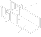
Technical scheme of the present invention is: comprise body and baffle plate, described baffle plate bottom is provided with through hole, and the biside plate of body is provided with corresponding one by one notch, and baffle plate is pegged graft and coordinated with notch.
The two ends projection of described baffle plate, the distance between convex edge is more than or equal to the distance between body biside plate outer wall.
In the present invention, body bottom is provided with through hole, and body biside plate is provided with corresponding one by one notch, and baffle plate is pegged graft and coordinated with notch.During punching, the groove of body is put in one end of pipe collar, and withstands baffle plate, when drill bit bores downwards, from the through hole of body, gets out.When the different pitch-row of needs, only baffle plate need be inserted to corresponding notch.
Accompanying drawing explanation
Fig. 1 is the schematic perspective view of structure of the present invention.
Fig. 2 is the decomposing schematic representation of Fig. 1.
The specific embodiment
Below in conjunction with drawings and Examples, the present invention is described in further detail, but does not form any limitation of the invention.Shown in Fig. 1 and Fig. 2, the present invention includes body 1 and baffle plate 2, body 1 is groove structure, and described baffle plate 2 bottoms are provided with through hole, and the biside plate of body 1 is provided with corresponding one by one notch, and baffle plate 2 is pegged graft and coordinated with notch.The two ends projection of described baffle plate 2, the distance between convex edge is more than or equal to the distance between body 1 biside plate outer wall, makes baffle plate 2 be difficult for skidding off.
During operation, body 1 is fixed on drilling machine, and makes drill bit relative with the hole on body 1, and body 1 below should reserve the space of punching to drill bit.Baffle plate 2 inserts on body 1 in corresponding notch, and body 1 groove is put on one side that pipe collar need to be punched, and baffle plate 2 is withstood in its end, now, under drill bit, bores pipe collar is got to through hole.Each institute punches, and the distance between the limit of its Kong Xinyu pipe collar is all the same, therefore, the invariant position in hole while changing pipe collar, the interchangeability of pipe collar is good.
Claims (2)
1. a positional punch mould, is characterized in that: comprise body (1) and baffle plate (2), described baffle plate (2) bottom is provided with through hole, and the biside plate of body (1) is provided with corresponding one by one notch, and baffle plate (2) is pegged graft and coordinated with notch.
2. positional punch mould according to claim 1, is characterized in that: the two ends projection of described baffle plate (2), the distance between convex edge is more than or equal to the distance between body (1) biside plate outer wall.
Priority Applications (1)
| Application Number | Priority Date | Filing Date | Title |
|---|---|---|---|
| CN201410013888.2A CN103752903A (en) | 2014-01-13 | 2014-01-13 | Positioning and punching die |
Applications Claiming Priority (1)
| Application Number | Priority Date | Filing Date | Title |
|---|---|---|---|
| CN201410013888.2A CN103752903A (en) | 2014-01-13 | 2014-01-13 | Positioning and punching die |
Publications (1)
| Publication Number | Publication Date |
|---|---|
| CN103752903A true CN103752903A (en) | 2014-04-30 |
Family
ID=50520306
Family Applications (1)
| Application Number | Title | Priority Date | Filing Date |
|---|---|---|---|
| CN201410013888.2A Pending CN103752903A (en) | 2014-01-13 | 2014-01-13 | Positioning and punching die |
Country Status (1)
| Country | Link |
|---|---|
| CN (1) | CN103752903A (en) |
Citations (8)
| Publication number | Priority date | Publication date | Assignee | Title |
|---|---|---|---|---|
| EP0584729A1 (en) * | 1992-08-26 | 1994-03-02 | Leo Klapperich | Drilling device for dowel holes |
| CN2691724Y (en) * | 2004-01-06 | 2005-04-13 | 承德新新钒钛股份有限公司 | Bar stock on line automatic tapping machine |
| CN2774700Y (en) * | 2004-12-08 | 2006-04-26 | 潘建辰 | Automatic linear positioner |
| CN2882859Y (en) * | 2006-03-15 | 2007-03-28 | 周兴亮 | Digital controlled boring machine |
| CN101244540A (en) * | 2007-02-13 | 2008-08-20 | 鸿富锦精密工业(深圳)有限公司 | Grinding clamper |
| CN202447951U (en) * | 2012-01-06 | 2012-09-26 | 湖北蓝天铝合金制品有限公司 | Saw gauge table |
| CN202964227U (en) * | 2012-12-03 | 2013-06-05 | 江苏鑫顺不锈钢制品有限公司 | Tool for working table of sawing machine |
| CN103465084A (en) * | 2013-08-29 | 2013-12-25 | 山西腾龙煤机修配有限公司 | Anchor rod measuring and cutting device |
-
2014
- 2014-01-13 CN CN201410013888.2A patent/CN103752903A/en active Pending
Patent Citations (8)
| Publication number | Priority date | Publication date | Assignee | Title |
|---|---|---|---|---|
| EP0584729A1 (en) * | 1992-08-26 | 1994-03-02 | Leo Klapperich | Drilling device for dowel holes |
| CN2691724Y (en) * | 2004-01-06 | 2005-04-13 | 承德新新钒钛股份有限公司 | Bar stock on line automatic tapping machine |
| CN2774700Y (en) * | 2004-12-08 | 2006-04-26 | 潘建辰 | Automatic linear positioner |
| CN2882859Y (en) * | 2006-03-15 | 2007-03-28 | 周兴亮 | Digital controlled boring machine |
| CN101244540A (en) * | 2007-02-13 | 2008-08-20 | 鸿富锦精密工业(深圳)有限公司 | Grinding clamper |
| CN202447951U (en) * | 2012-01-06 | 2012-09-26 | 湖北蓝天铝合金制品有限公司 | Saw gauge table |
| CN202964227U (en) * | 2012-12-03 | 2013-06-05 | 江苏鑫顺不锈钢制品有限公司 | Tool for working table of sawing machine |
| CN103465084A (en) * | 2013-08-29 | 2013-12-25 | 山西腾龙煤机修配有限公司 | Anchor rod measuring and cutting device |
Similar Documents
| Publication | Publication Date | Title |
|---|---|---|
| EP2204245B1 (en) | Method for assembling heat sink | |
| CN103658392A (en) | Pipe hoop stamping die | |
| KR101772469B1 (en) | Transfer die method for manufacturing a diffuser capped on a single die | |
| US20060072290A1 (en) | Heat-dissipating device with heat conductive tubes | |
| CN103286200A (en) | Brake shoe bending plate continuous die and method for using continuous die to machine brake shoe bending plate | |
| BR112018014338A2 (en) | pressing machine and method for manufacturing a press-shaped product | |
| US20200290106A1 (en) | Stamping method and stamping apparatus | |
| CN103752903A (en) | Positioning and punching die | |
| CN102366795A (en) | Nut riveting and punching die | |
| CN107252847B (en) | Stamping upper die | |
| CN105458069A (en) | Full-automatic round tube punching machine | |
| CN204735633U (en) | Insert gilled radiator riveting tools | |
| CN204449422U (en) | A kind of simple steel pipe electric drill perforate locator | |
| CN209935659U (en) | Small ring forging piece punching sheath die | |
| CN207857618U (en) | A kind of hole punched device | |
| CN203854055U (en) | Stamping missing prevention and forming sequence error prevention system for forming flexible circuit board for multiple times | |
| CN215431042U (en) | Punching jig for connector outer sleeve | |
| CN211464588U (en) | Punch press template with PCB mistake proofing hole | |
| CN205165604U (en) | Stamping die | |
| US3402623A (en) | Method of making a die set | |
| TWI680024B (en) | Method for inlaying nut on metal sheet | |
| CN204381198U (en) | End plate progressive die equipment | |
| JP2019181520A (en) | Press processing device | |
| CN203972657U (en) | The continuous hole expansion die of a kind of oil pipe list station | |
| CN210754690U (en) | Medical thigh arc layer board forming die |
Legal Events
| Date | Code | Title | Description |
|---|---|---|---|
| C06 | Publication | ||
| PB01 | Publication | ||
| C10 | Entry into substantive examination | ||
| SE01 | Entry into force of request for substantive examination | ||
| C02 | Deemed withdrawal of patent application after publication (patent law 2001) | ||
| WD01 | Invention patent application deemed withdrawn after publication |
Application publication date: 20140430 |