CN103742425A - Energy conservation correcting method for water circulation system - Google Patents
Energy conservation correcting method for water circulation system Download PDFInfo
- Publication number
- CN103742425A CN103742425A CN201410030594.0A CN201410030594A CN103742425A CN 103742425 A CN103742425 A CN 103742425A CN 201410030594 A CN201410030594 A CN 201410030594A CN 103742425 A CN103742425 A CN 103742425A
- Authority
- CN
- China
- Prior art keywords
- pump
- flow
- curve
- lift
- energy conservation
- Prior art date
- Legal status (The legal status is an assumption and is not a legal conclusion. Google has not performed a legal analysis and makes no representation as to the accuracy of the status listed.)
- Granted
Links
Images


Abstract
The invention discloses an energy conservation correcting method for a water circulation system. The energy conservation correcting method includes measuring characteristic curves of pumps; determining intersections b on the characteristic curves of the water pumps according to shutoff point heads H', flow rates Qb and heads Hb of the pumps; determining actually required flow rates Qc according to rated points c of motors of the pumps. The optimal energy conservation transformation working condition points of equipment are intersections c' of the flow rates Qc and the heads Hb. The energy conservation correcting method has the advantages that the optimal energy conservation transformation working condition points of the equipment are selected according to the characteristic curves and are combined with actual conditions of fields, accordingly, adverse and unreasonable factors in the original system can be corrected, the delivery efficiency of the system can be improved, and purposes of energy conservation and consumption reduction can be achieved; the energy conservation correcting method is applicable to water circulation systems.
Description
Technical field
The invention belongs to water pump application, specially refer to the energy-conservation method for correcting of water circulation system.
Background technique
At present, the following problem of water circulation system ubiquity: water pump does not use at its intrinsic optimum operating condition point, vibrations are large, noise greatly, even there will be the air horsepower of water pump output to be greater than the power of institute's gas-distributing motor, cause motor ablation, during generally by design, power gain makes the rated point work of water pump at institute's gas-distributing motor.Although adopt this way to guarantee the normal operation of pump, occurred that rated lift is too high, the actual situation that there will be low lift, large flow, poor efficiency, high energy consumption of using.
Summary of the invention
The present invention will solve the problems of the technologies described above.
The present invention is achieved in that the energy-conservation method for correcting of a kind of water circulation system, it is characterized in that: first measure pump curve, according to pump, close dead point lift H ', flow Qb, lift of pump Hb, determines the intersection point b on water pump curve, according to the rated point c point of pump institute gas-distributing motor, determines actual required flow Qc, the intersection point of flow Qc and lift Hb is c ', is the optimum operating condition point of this device energy conservation transformation.
Described mensuration pump curve adopts following formula:
1), determining of lift H: row Bernoulli's equation between pump intake and extrusion mouth; Because pipeline between 2 o'clock is very short, fricting resistance loss can be ignored.Can think that again flow velocity equates.Therefore have,
H---lift of pump (m);
P1---pump inlet degree of vacuum (Pa);
The pressure (Pa) of P2---pump discharge place liquid;
U---fluid is at the flow velocity (m/s) of pump import and export;
Z1---import vacuum gauge setting height(from bottom) (m);
Z2---delivery gauge setting height(from bottom) (m);
ρ-N=N
electricity× k-fluid density 1 × 10
3(kg/m
3);
G---gravity accleration 9.8(m/s
2);
2), the calculating of air horsepower:
N---air horsepower (KW);
N
electricity---electric power meter show value (KW),
K---motor-driven efficiency, desirable k=0.82;
3), the calculating of shaft efficiency η:
The efficiency eta of pump is the useful horsepower Ne of pump and the ratio of air horsepower N, and useful horsepower Ne is unit time N
ethe actual power obtaining during=ρ gQH inner fluid mass flow rate process pump, shaft work
 rate N is the power that in the unit time, pump shaft obtains from motor, and both differences have reflected the size of hydraulic loss, volumetric loss and mechanical loss, and the useful horsepower Ne of pump can calculate with following formula:
Ne---useful horsepower (KW);
η---shaft efficiency;
ρ---fluid density 1 × 10
3(kg/m
3);
G---gravity accleration 9.8(m/s
2);
Q---flow (m
3/ h);
H---lift of pump (m);
4) calculating when, rotating speed changes:
Pump curve is the measuring gained under certain rotating speed, but, in fact induction motor is when torque changes, its rotating speed can change, and along with the variation of flow Q, the rotation speed n of multiple experimental points is incited somebody to action difference to some extent like this, therefore before drawing characteristic curve, measured data must be scaled to certain certain rotation speed n 1 time, get the rated speed 2900rpm of centrifugal pump, formula is as follows:
Q
1---the flow (m under rated speed 2900rpm
3/ h);
Q---flow (m
3/ h);
N---actual measurement rotating speed (rpm);
N
1---rated speed 2900(rpm);
H---lift of pump (m);
H
1---the lift (m) under rated speed 2900rpm.
The operating procedure of described mensuration pump curve mapping is as follows:
1), centrifugal pump is answered pump priming exhaust before startup;
2), instrument self check, open pump inlet valve, close pump discharge valve, runin centrifugal pump, checks that the sound of motor rotation is normal, the in the right direction of centrifugal pump running is qualified;
3), centrifugal pump will start in the situation that outlet valve cuts out, and opens centrifugal pump, when the rotating speed of pump reaches after rated speed, opens outlet valve;
4), when test, by instrument, instrument, change gradually the aperture of rate of discharge modulating valve, make pump discharge flow from 0m
3/ h increases to 70m gradually
3/ h increases 10m at every turn
3/ h, under each flow, after system stability flows 5 minutes, reads corresponding data, and Characteristics of Centrifugal Pump is tested the test data that mainly need obtain and is: flow Q, pump inlet and outlet pressure, input power, revolution speed n, height difference Z between two pressure-measuring points
0for 2m;
5), first closing outlet valve stops again;
6), data are transformed under same rotating speed, obtained point is coupled together with a smooth curve, just obtained the former design characteristics curve H-Q under this rotating speed, former pump power characteristic curve P-Q, efficiency flow curve Eff-Q.
The optimum operating condition point of described device energy conservation transformation, refer to equipment is carried out after reducing energy consumption, according to measuring the formula of pump curve employing, the operating procedure of mapping, obtain measuring characteristic curve H-Q(502 after pump correction), take by adjusting valve openings size, take more water-change pump and motor, redesign to change the method for original impeller, can adopt one or more the combination in three kinds of methods to realize.
The present invention selects the optimum operating condition point of device energy conservation transformation according to characteristic curve, in conjunction with on-site actual situations, revise the unfavorable and irrational factor in original system, improves the transfer efficiency of system, reaches energy-saving and cost-reducing object.
Accompanying drawing explanation
Fig. 1 is the instrument and apparatus scheme of installation of the embodiment of the present invention one.
Fig. 2 is the performance chart that the embodiment of the present invention one is surveyed and drawn.
Fig. 3 is the system service chart of the embodiment of the present invention two.
Fig. 4 is the system service chart of the embodiment of the present invention three.
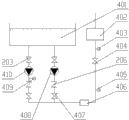
Fig. 5 is the system service chart of the embodiment of the present invention four.
Fig. 6 is the performance chart of structure of the present invention.
In figure: 101, tank; 102, hand stop valve; 103, thermometer; 104, flowmeter; 105, pressure gauge; 106, wattmeter; 107, frequency variator; 108, pump; 109, bleed valve; 110, vacuum gauge; 111, drain valve; 112, filter; 201, cooling tower; 202, turbid ring hot-tub; 203, stop valve; 204, water pump A; 205, pressure gauge A; 206, safety check; 207, stop valve A; 208, stop valve B; 209, water pump B; 210, shutoff valve C; 211, water pump C; 301, eddy flow well; 302, water pump D; 303, water pump E; 304, stop valve D; 305, water pump F; 306, water pump G; 401, turbid ring water cooling pond; 402, use equipment; 403, pressure gauge B; 404, stop valve E; 405, pressure gauge C; 406, filter; 407, stop valve F; 408, water pump H; 409, pressure gauge D; 410, water pump I; 501, former design characteristics curve H-Q; 502, revise rear characteristic curve H-Q; 503, former pump power characteristic curve P-Q.
Embodiment
Below in conjunction with following examples, the invention will be further described, but not as limitation of the present invention:
Embodiment one, please refer to Fig. 1, Fig. 2 and table 1, water is extracted out from tank 101, through filter 112, pump 108, flowmeter 104, hand stop valve 102, flows back to tank 101, and the valve 111 that drains on tank 101 cuts out; Vacuum gauge 110, outlet port setting pressure table 105, thermometer 103 are installed by pump 108 inlets.According to the value of the flow Q, the air horsepower N that measure, rotation speed n, import vacuum gauge P1 and delivery gauge P2, calculate H, η and make H~Q, N~Q, Eff-Q figure.
Table 1
Embodiment two, please refer to Fig. 3 and table 2, the energy-conservation method for correcting of tower pump on the turbid ring in certain steel mill's turbid circulating water system.In this system, being equipped with altogether water pump is 3, and the method for operation is dual-purpose one standby, and water pump structure is horizontal single-stage double suction pump, in the position of 0 meter of absolute altitude; Turbid ring hot-tub 202 is in the position of 3 meters of absolute altitudes; Cooling tower 201 is in the position of 8 meters of absolute altitudes.During system operation, water flows out from turbid ring hot-tub 202, through stop valve 203, water pump, safety check 206, stop valve, is finally sent to the cooling tower 201 of eminence.Close except stop valve B208, stop valve A207 and


Table 2
By measuring former design characteristics curve H-Q501 and obtaining the optimum operating condition point of reducing energy consumption, in conjunction with on-the-spot modal analysis, draw, this system exists artificial increase resistance to realize the balance of whole system, and it is 1570m that actual whole system needs flow
3/ h, actual required lift is that head pressure reduction adds that pipe damage is taken as 10m, and the former design process of this system too increases coefficient, departs from actual conditions point, can only realize actual demand by the method for adjusting valve.
Draw after above-mentioned conclusion, redesign or type selecting parameter: flow Q=785m
3/ h, lift H=10m, for cost-saving, motor is without replacing, and water pump structure is constant.Please refer to Fig. 3 and table 3, after transformation, stop valve A207 and shutoff valve C 210 all open 100%, the operating pressure 0.35MPa of system, operate power 65KW, power saving rate 68.9%.Measure characteristic curve H-Q502 after reducing energy consumption correction, it with the former design characteristics curve H-Q501 of mensuration between there is energy-conservation region.
| Former operate power | Existing operate power | Power saving rate | Year amount of electricity saving |
| 209KW | 65KW | 68.9% | 120KW·h |
Table 3
Embodiment three, please refer to Fig. 4 and table 4, the energy-conservation method for correcting of eddy flow well elevator pump in certain steel mill's turbid circulating water system.In this system, being equipped with altogether water pump is 4, and the method for operation is that three use one are standby, and water pump structure is vertical type non-sealed self-controlling self-priming pump, the position in absolute altitude-1 meter; The position of eddy flow well 301 in absolute altitude-5 meter; Turbid ring hot-tub 202 is in the position of 3 meters of absolute altitudes.During system operation, water is extracted out from eddy flow well 301, through stop valve 203, water pump, safety check 206, stop valve, is finally sent to the turbid ring hot-tub 202 of eminence.Except stop valve D304 closes, remaining stop valve equal 100% is opened; The operating pressure 0.13MPa of water pump D302, operation frequency 30Hz, power 75KW; The operating pressure 0.13MPa of water pump E303, operation frequency 30Hz, power 73.3KW; The operating pressure 0.13MPa of water pump G306, operation frequency 30Hz, power 74.3KW; Reserve pump F305 stops transport.35 ℃ of test external temperatures, raw water pump nameplate parameter is: flow Q=830m
3/ h, lift H=42m, necessary electromotor is 4P-220KW.

Table 4
This system operation water pump makes the balance of whole system by the method for frequency conversion, although this method can be saved power consumption, pump efficiency is too low, the way of curing the symptoms, not the disease.
By measuring former design characteristics curve H-Q501 and obtaining the optimum operating condition point of reducing energy consumption, in conjunction with on-the-spot modal analysis, draw, for guaranteeing the balance of whole water system, it is 1570m that this system needs flow
3/ h, actual required lift is that head pressure reduction adds that pipe damages and is taken as 15m, and the former design process of this system too increases coefficient, departs from actual conditions point, can only realize actual demand by the method such as adjust frequency.
Draw after above-mentioned conclusion, redesign or type selecting parameter: flow Q=525m
3/ h, lift H=15m, more water-change pump and motor, water pump structure is vertical efficient type self-controlling self-priming pump, electric drilling match power is 4P-30KW.Please refer to Fig. 4 and table 5, after transformation, the operation frequency 50Hz of system, operate power 85.5KW, power saving rate 61.6%.Measure characteristic curve H-Q502 after reducing energy consumption correction, it with the former design characteristics curve H-Q501 of mensuration between there is energy-conservation region.
| Former operate power | Existing operate power | Node rate | Year amount of electricity saving |
| 222.6KW | 85.5KW | 61.6% | 120KW·h |
Table 5
Embodiment four, please refer to Fig. 5 and table 6, the energy-conservation method for correcting of turbid ring low pressure pump in certain steel mill's turbid circulating water system.In this system, being equipped with altogether water pump is 2, and the method for operation is the using and the reserved, and water pump structure is horizontal single-stage double suction pump, in the position of 0 meter of absolute altitude; Turbid ring water cooling pond 401 is in the position of 3 meters of absolute altitudes; Use equipment 402 is in the position of 5 meters of absolute altitudes.During system operation, water flows out from turbid ring water cooling pond 401, through stop valve 203, water pump, safety check 206, stop valve, is finally sent to the use equipment 402 of eminence.Except stop valve F407 closes, stop valve E404 opens 30%, and remaining stop valve equal 100% is opened; The operating pressure 0.62MPa of water pump I410, operation frequency 50Hz, power 160KW; Water pump H408 stops transport.35 ℃ of test external temperatures, raw water pump nameplate parameter is: flow Q=720m
3/ h, lift H=49m, necessary electromotor is 4P-160KW.

Table 6
By measuring former design characteristics curve H-Q501 and obtaining the optimum operating condition point of reducing energy consumption, in conjunction with on-the-spot modal analysis, draw, this system cannot make it reach field demand by the method for adjusting valve and adjustment electric machine frequency, and it is 600m that this system needs flow
3/ h, actual required lift is that head pressure reduction adds that pipe damage is taken as 35m, and the former design process of this system too increases coefficient, departs from actual conditions point.
Draw after above-mentioned conclusion, redesign parameter: flow Q=600m
3/ h, lift H=35m, pump case and motor are not changed, and redesign impeller pattern and change.Please refer to Fig. 5 and table 7, after transformation, stop valve E404 opens 100%, the operating pressure 0.62MPa of water pump I410, operation frequency 50Hz, operate power 85.75KW, power saving rate 46.4%.Measure characteristic curve H-Q502 after reducing energy consumption correction, it with the former design characteristics curve H-Q501 of mensuration between there is energy-conservation region.
| Former operate power | Existing operate power | Node rate | Year amount of electricity saving |
| 160KW | 85.75KW | 46.4% | 60KW·h |
Table 7.
Claims (4)
1. the energy-conservation method for correcting of water circulation system, it is characterized in that: first measure pump curve, according to pump, close dead point lift H ', flow Qb, lift of pump Hb, determines the intersection point b on water pump curve, according to the rated point c point of pump institute gas-distributing motor, determines actual required flow Qc, the intersection point of flow Qc and lift Hb is c ', is the optimum operating condition point of this device energy conservation transformation.
2. the energy-conservation method for correcting of a kind of water circulation system according to claim 1, is characterized in that: described mensuration pump curve adopts following formula:
1), lift H's determines
Row Bernoulli's equation between pump intake and extrusion mouth
By
Between 2 o'clock, pipeline is very short, and fricting resistance loss can be ignored, and can think that again flow velocity equates, therefore have
H—
-lift of pump (m);
P1---pump inlet degree of vacuum (Pa);
The pressure (Pa) of P2---pump discharge place liquid;
U---fluid is at the flow velocity (m/s) of pump import and export;
Z1---import vacuum gauge setting height(from bottom) (m);
Z2---delivery gauge setting height(from bottom) (m);
ρ---fluid density 1 × 10
3(kg/m
3);
G---gravity accleration 9.8(m/s
2);
2), the calculating of air horsepower N
N---air horsepower (KW);
N=N
electricity× k
N
electricity---electric power meter show value (KW);
K---motor-driven efficiency, desirable k=0.82;
3), the calculating of shaft efficiency η
The efficiency eta of pump is the useful horsepower Ne of pump and the ratio of air horsepower N, useful horsepower Ne is the actual power that unit time inner fluid mass flow rate obtains when the pump, air horsepower N is the power that in the unit time, pump shaft obtains from motor, both differences have reflected the size of hydraulic loss, volumetric loss and mechanical loss, and the useful horsepower Ne of pump can calculate with following formula:
N
e=ρgQH
Ne—
-useful horsepower (KW);
N---air horsepower (KW);
η---shaft efficiency;
ρ---fluid density 1 × 10
3(kg/m
3);
G---gravity accleration 9.8(m/s
2);
Q---flow (m
3/ h);
H---lift of pump (m);
4) calculating when, rotating speed changes
Pump curve is the measuring gained under certain rotating speed, but, in fact induction motor is when torque changes, its rotating speed can change, and along with the variation of flow Q, the rotation speed n of multiple experimental points is incited somebody to action difference to some extent like this, therefore before drawing characteristic curve, measured data must be scaled to certain certain rotation speed n 1 time, get the rated speed 2900rpm of centrifugal pump, formula is as follows:
Q
1---the flow (m under rated speed 2900rpm
3/ h);
Q---flow (m
3/ h);
N---actual measurement rotating speed (rpm);
N
1---rated speed 2900(rpm);
H---lift of pump (m);
H
1---the lift (m) under rated speed 2900rpm.
3. the energy-conservation method for correcting of a kind of water circulation system according to claim 1, is characterized in that: the operating procedure of described mensuration pump curve mapping is as follows:
1), centrifugal pump is answered pump priming exhaust before startup;
2), instrument self check, open pump inlet valve, close pump discharge valve, runin centrifugal pump, checks that the sound of motor rotation is normal, the in the right direction of centrifugal pump running is qualified;
3), centrifugal pump will start in the situation that outlet valve cuts out, and opens centrifugal pump, when the rotating speed of pump reaches after rated speed, opens outlet valve;
4), when test, by instrument, instrument, change gradually the aperture of rate of discharge modulating valve, make pump discharge flow from 0m
3/ h increases to 70m gradually
3/ h increases 10m at every turn
3/ h, under each flow, after system stability flows 5 minutes, reads corresponding data, and Characteristics of Centrifugal Pump is tested the test data that mainly need obtain and is: flow Q, pump inlet and outlet pressure, input power, revolution speed n, height difference Z between two pressure-measuring points
0for 2m;
5), first closing outlet valve stops again;
6), data are transformed under same rotating speed, obtained point is coupled together with a smooth curve, has just obtained the former design characteristics curve H-Q(501 under this rotating speed), former pump power characteristic curve P-Q(503), efficiency flow curve Eff-Q.
4. according to the energy-conservation method for correcting of a kind of water circulation system described in claim 1 or 2 or 3, it is characterized in that: according to the optimum operating condition point of described device energy conservation transformation, refer to equipment is carried out after reducing energy consumption, according to measuring the formula of pump curve employing, the operating procedure of mapping, obtain measuring characteristic curve H-Q(502 after pump correction), take by adjusting valve openings size, take more water-change pump and motor, redesign to change the method for original impeller, can adopt one or more the combination in three kinds of methods to realize.
Priority Applications (1)
| Application Number | Priority Date | Filing Date | Title |
|---|---|---|---|
| CN201410030594.0A CN103742425B (en) | 2014-01-22 | 2014-01-22 | Energy conservation correcting method for water circulation system |
Applications Claiming Priority (1)
| Application Number | Priority Date | Filing Date | Title |
|---|---|---|---|
| CN201410030594.0A CN103742425B (en) | 2014-01-22 | 2014-01-22 | Energy conservation correcting method for water circulation system |
Publications (2)
| Publication Number | Publication Date |
|---|---|
| CN103742425A true CN103742425A (en) | 2014-04-23 |
| CN103742425B CN103742425B (en) | 2017-01-18 |
Family
ID=50499477
Family Applications (1)
| Application Number | Title | Priority Date | Filing Date |
|---|---|---|---|
| CN201410030594.0A Active CN103742425B (en) | 2014-01-22 | 2014-01-22 | Energy conservation correcting method for water circulation system |
Country Status (1)
| Country | Link |
|---|---|
| CN (1) | CN103742425B (en) |
Cited By (10)
| Publication number | Priority date | Publication date | Assignee | Title |
|---|---|---|---|---|
| CN104298875A (en) * | 2014-10-13 | 2015-01-21 | 浙江工业大学之江学院 | Centrifugal pump flow prediction method based on power and differential pressure |
| CN104895795A (en) * | 2015-04-23 | 2015-09-09 | 江苏大学 | Multi-working condition hydraulic design method of centrifugal pump |
| CN105512948A (en) * | 2015-12-22 | 2016-04-20 | 扬州大学 | Automatic water quantity measuring method of small-scale pumping station |
| CN108571453A (en) * | 2018-04-11 | 2018-09-25 | 杭州志驱传动技术有限公司 | Adjust automatically control method is arranged in hot water control system of invariable pressure |
| CN108825520A (en) * | 2018-05-04 | 2018-11-16 | 四川省宜宾惠美线业有限责任公司 | A kind of energy-efficient application method of centrifugal water pump |
| CN110210158A (en) * | 2019-06-11 | 2019-09-06 | 长沙凯仁节能技术有限公司 | The remodeling method of customized energy-efficient water pump |
| CN110469893A (en) * | 2019-08-26 | 2019-11-19 | 中国计量大学 | A kind of circulating pump self-adaptation control method adjusted based on ratio pressure |
| CN111368246A (en) * | 2020-03-30 | 2020-07-03 | 河南九域恩湃电力技术有限公司 | Condensate pump energy-saving modification evaluation method based on performance actual measurement |
| CN111597687A (en) * | 2020-04-17 | 2020-08-28 | 西安理工大学 | Method for optimizing working condition efficiency of water pump of variable-speed pumped storage unit |
| CN111832137A (en) * | 2020-07-29 | 2020-10-27 | 上海凯泉泵业(集团)有限公司 | Intelligent centrifugal pump design method based on database |
Citations (6)
| Publication number | Priority date | Publication date | Assignee | Title |
|---|---|---|---|---|
| CN101666319A (en) * | 2009-09-29 | 2010-03-10 | 长沙翔鹅节能技术有限公司 | Energy saving method for circulating water system |
| CN102052564A (en) * | 2010-10-27 | 2011-05-11 | 杨宝良 | Method for optimizing circulating cooling water convey system |
| CN102518946A (en) * | 2012-01-09 | 2012-06-27 | 浙江科维节能技术有限公司 | Energy saving method for cooling water circulation system |
| CN102536962A (en) * | 2012-03-31 | 2012-07-04 | 青岛楚天节能技术有限公司 | Optimization method of circulating fluid system |
| WO2012099242A1 (en) * | 2011-01-21 | 2012-07-26 | 株式会社 荏原製作所 | Water supply device |
| KR20130097007A (en) * | 2012-02-23 | 2013-09-02 | 양철수 | Pump system for energy saving and it's control process |
-
2014
- 2014-01-22 CN CN201410030594.0A patent/CN103742425B/en active Active
Patent Citations (6)
| Publication number | Priority date | Publication date | Assignee | Title |
|---|---|---|---|---|
| CN101666319A (en) * | 2009-09-29 | 2010-03-10 | 长沙翔鹅节能技术有限公司 | Energy saving method for circulating water system |
| CN102052564A (en) * | 2010-10-27 | 2011-05-11 | 杨宝良 | Method for optimizing circulating cooling water convey system |
| WO2012099242A1 (en) * | 2011-01-21 | 2012-07-26 | 株式会社 荏原製作所 | Water supply device |
| CN102518946A (en) * | 2012-01-09 | 2012-06-27 | 浙江科维节能技术有限公司 | Energy saving method for cooling water circulation system |
| KR20130097007A (en) * | 2012-02-23 | 2013-09-02 | 양철수 | Pump system for energy saving and it's control process |
| CN102536962A (en) * | 2012-03-31 | 2012-07-04 | 青岛楚天节能技术有限公司 | Optimization method of circulating fluid system |
Non-Patent Citations (2)
| Title |
|---|
| HAPPYHJR1990: ""离心泵特性测定实验"", 《百度文库》, 12 July 2012 (2012-07-12), pages 1 - 8 * |
| 屈俭等: ""循环水系统节能改造实践"", 《现代冶金》, vol. 41, no. 2, 30 April 2013 (2013-04-30), pages 59 - 61 * |
Cited By (17)
| Publication number | Priority date | Publication date | Assignee | Title |
|---|---|---|---|---|
| CN104298875A (en) * | 2014-10-13 | 2015-01-21 | 浙江工业大学之江学院 | Centrifugal pump flow prediction method based on power and differential pressure |
| CN104298875B (en) * | 2014-10-13 | 2017-10-31 | 浙江工业大学之江学院 | A kind of Centrifugal Pump Forecasting Methodology based on power and pressure difference |
| CN104895795A (en) * | 2015-04-23 | 2015-09-09 | 江苏大学 | Multi-working condition hydraulic design method of centrifugal pump |
| CN104895795B (en) * | 2015-04-23 | 2018-07-06 | 江苏大学 | A kind of centrifugal pump multi-state Hydraulic Design Method |
| CN105512948A (en) * | 2015-12-22 | 2016-04-20 | 扬州大学 | Automatic water quantity measuring method of small-scale pumping station |
| CN108571453A (en) * | 2018-04-11 | 2018-09-25 | 杭州志驱传动技术有限公司 | Adjust automatically control method is arranged in hot water control system of invariable pressure |
| CN108571453B (en) * | 2018-04-11 | 2019-08-13 | 杭州志驱传动技术有限公司 | Adjust automatically control method is arranged in hot water control system of invariable pressure |
| CN108825520A (en) * | 2018-05-04 | 2018-11-16 | 四川省宜宾惠美线业有限责任公司 | A kind of energy-efficient application method of centrifugal water pump |
| CN110210158A (en) * | 2019-06-11 | 2019-09-06 | 长沙凯仁节能技术有限公司 | The remodeling method of customized energy-efficient water pump |
| CN110210158B (en) * | 2019-06-11 | 2023-06-06 | 长沙凯仁节能技术有限公司 | Transformation method of energy-saving water pump |
| CN110469893A (en) * | 2019-08-26 | 2019-11-19 | 中国计量大学 | A kind of circulating pump self-adaptation control method adjusted based on ratio pressure |
| CN111368246A (en) * | 2020-03-30 | 2020-07-03 | 河南九域恩湃电力技术有限公司 | Condensate pump energy-saving modification evaluation method based on performance actual measurement |
| CN111368246B (en) * | 2020-03-30 | 2023-03-24 | 河南九域恩湃电力技术有限公司 | Condensate pump energy-saving modification evaluation method based on performance actual measurement |
| CN111597687A (en) * | 2020-04-17 | 2020-08-28 | 西安理工大学 | Method for optimizing working condition efficiency of water pump of variable-speed pumped storage unit |
| CN111597687B (en) * | 2020-04-17 | 2024-03-29 | 西安理工大学 | Variable-speed pumped storage unit water pump working condition efficiency optimizing method |
| CN111832137A (en) * | 2020-07-29 | 2020-10-27 | 上海凯泉泵业(集团)有限公司 | Intelligent centrifugal pump design method based on database |
| CN111832137B (en) * | 2020-07-29 | 2022-11-29 | 上海凯泉泵业(集团)有限公司 | Intelligent centrifugal pump design method based on database |
Also Published As
| Publication number | Publication date |
|---|---|
| CN103742425B (en) | 2017-01-18 |
Similar Documents
| Publication | Publication Date | Title |
|---|---|---|
| CN103742425A (en) | Energy conservation correcting method for water circulation system | |
| Wang et al. | The method for determining blade inlet angle of special impeller using in turbine mode of centrifugal pump as turbine | |
| Tan et al. | Hydraulic design and pre-whirl regulation law of inlet guide vane for centrifugal pump | |
| CN106050722B (en) | Complete performance surge controlling method and system based on the principle of similitude | |
| CN103452824B (en) | Based on the energy saving in fans and pumps system of the minimum power algorithm of flow-power curve | |
| CN104454564B (en) | Based on the axial-flow pump device diffuser hydraulic optimization method of test | |
| CN110298470A (en) | On demand to the integrated recirculated water power-saving technology of energy | |
| CN102937104A (en) | Turbine compressor test system | |
| CN102183157A (en) | Energy-saving control device and method for condenser system of power plant | |
| CN105571844A (en) | Method for measuring heating ventilation air conditioning system water pump or valve flow | |
| CN112628515A (en) | Method for manufacturing orifice plate by using flowmeter | |
| CN100561043C (en) | A kind of boiler feedwater flow control and pressure compensating system | |
| CN104699888B (en) | A kind of hydraulic turbine design method based on pump turbine | |
| CN107829975B (en) | A kind of side channel pump hydraulic performance fast optimal design method | |
| CN102434221A (en) | Impeller of hydraulic turbine | |
| CN202599140U (en) | Circulating water cooling tower | |
| CN106286790B (en) | A kind of heat dissipating method of combined radiating device for wind-power electricity generation reduction gear box | |
| CN108019344B (en) | Method for testing efficiency of electric water supply pump set | |
| CN207673562U (en) | A kind of easy-to-mount associated mode air conditioning pump | |
| CN208999836U (en) | Pump based on hydraulic dynamometer makees Turbine Performance experimental rig | |
| CN208835937U (en) | A kind of coolant liquid self-loopa permanent magnet speed regulation device | |
| CN216899056U (en) | Seawater direct current cooling unit circulating water volume measuring system | |
| CN205939468U (en) | Marine change water yield air conditioning system | |
| CN219587781U (en) | Vacuum pump cooling system | |
| CN204435469U (en) | A kind of irrigation and water conservancy irrigation pumping station pumping system |
Legal Events
| Date | Code | Title | Description |
|---|---|---|---|
| C06 | Publication | ||
| PB01 | Publication | ||
| C10 | Entry into substantive examination | ||
| SE01 | Entry into force of request for substantive examination | ||
| C14 | Grant of patent or utility model | ||
| GR01 | Patent grant | ||
| PE01 | Entry into force of the registration of the contract for pledge of patent right |
Denomination of invention: Correction method for energy saving of water circulation system Effective date of registration: 20220728 Granted publication date: 20170118 Pledgee: Bank of Jiangsu Co.,Ltd. Taizhou Branch Pledgor: JIANGSU DOUBLE-WHEEL PUMP MACHINERY CO.,LTD. Registration number: Y2022980011383 |
|
| PE01 | Entry into force of the registration of the contract for pledge of patent right |