CN103707662A - Printer and printer head driving method - Google Patents
Printer and printer head driving method Download PDFInfo
- Publication number
- CN103707662A CN103707662A CN201310430860.4A CN201310430860A CN103707662A CN 103707662 A CN103707662 A CN 103707662A CN 201310430860 A CN201310430860 A CN 201310430860A CN 103707662 A CN103707662 A CN 103707662A
- Authority
- CN
- China
- Prior art keywords
- printhead
- threshold value
- printer
- voltage application
- Prior art date
- Legal status (The legal status is an assumption and is not a legal conclusion. Google has not performed a legal analysis and makes no representation as to the accuracy of the status listed.)
- Pending
Links
Images


Abstract
The invention discloses a printer and a printer head driving method. Based on operator's requirement, printing with appropriate quality and speed can be done. The printer comprises a printer head (21), a coil driving part (27), a temperature detection part (28) for detecting the temperature inside the printer head (21), a threshold setting part (32) for controlling the threshold of the temperature inside the printer head (21) by setting corresponding to a printing mode; and a printing condition setting part (33) for setting the printing condition for lowering temperature inside the printer head (21) when the detection temperature is set above the set threshold. When setting the threshold, the printing quality won't be reduced without reducing printing density. When setting the threshold, the printing speed won't be lowered.
Description
Technical field
The present invention relates to printer and printhead driving method.
Background technology
In the past, the image processing systems such as printer, duplicator, facsimile machine, compounding machine, for example impact printer has printhead, make to be provided in print needle on printhead optionally before so that impact ink ribbon, the China ink of ink ribbon is transferred in the paper using of medium, thereby prints.
Therefore, on described printhead, be equipped with the iron core that quantity is identical with printing pin, corresponding to this each iron core, swing and be equipped with freely the armature that front end is provided with described print needle.Then, by applying predetermined voltage and provide drive current to coil to being provided in each iron core coil around, when making iron core produce electromagnetic force, armature is attracted by iron core, and print needle is advanced.
In addition, in described printhead, follow to coil and drive current is provided and produces heat, when the temperature of coil is followed hot generation and raise, likely damage coil.
Therefore, provide such printer: the Temperature Setting lower than the heat resisting temperature of coil become to threshold value, the temperature of magnetic test coil, when detected temperature is that detected temperatures is during higher than threshold value, drive discontinuously printhead, or make the bracket that is equipped with printhead only to a direction, move to drive printhead, reduce the so-called thermal control (for example,, with reference to patent documentation 1) of the temperature of coil.
Yet, in the printer of patent documentation 1, in the situation that having carried out described thermal control, control and compare with common printing, print needed time lengthening, the handling capacity of printer reduces.
Therefore, in order not make the handling capacity of printer reduce, can consider the threshold value that raises, set the value approaching with the heat resisting temperature of coil for, reduce the frequency that carries out described thermal control.
Yet, when during continuing to print, the temperature of coil raises gradually, the resistance value of coil increases, and drive current is difficult to flow into coil, the power (hereinafter referred to as " impact force ") that makes print needle impact ink ribbon reduces, and the concentration of the word of printing etc. is that gradation of drop-out colour reduces.
Therefore, provide such printer: described detected temperatures is higher, to coil, executing the alive time is voltage application time just longer (for example,, with reference to patent documentation 2).
In this case, when the temperature rising of coil, when the resistance value of coil increases, voltage application time extends, thereby can guarantee to drive the needed energy of printhead.Therefore, can produce certain impact force, can prevent that gradation of drop-out colour from reducing.
[patent documentation 1] Japanese kokai publication hei 1-308647 communique
[patent documentation 2] Japanese kokai publication sho 60-115477 communique
Yet, in the printer of patent documentation 2, when described detected temperatures is during higher than predetermined value, even if extend voltage application time, can not produce certain impact force, gradation of drop-out colour reduces, and print quality reduces.
Like this, in the prior art, when increasing threshold value, while setting the approaching value of heat resisting temperature with coil for, although be not easy to carry out thermal control, can prevent that the handling capacity of printer from reducing, still, when the temperature of coil raises, gradation of drop-out colour reduces, and print quality reduces.And when reducing threshold value, although can prevent that print quality from reducing, the handling capacity of printer reduces.
Summary of the invention
The object of the invention is to, solve the problem of described existing printer, provide a kind of can be according to operator to requirement of the kind of print data, form of medium etc., the printer and the printhead driving method that print with suitable print quality, suitable print speed.
For this reason, printer of the present invention has: printhead, and it has coil and type element; Coil drive portion, it provides drive current to described coil, drives described type element to print; Temperature detecting part, it is for detection of the internal temperature of described printhead; Threshold portion, it sets the 1st threshold value with printing model and accordingly than a threshold value in the 2nd low threshold value of the 1st threshold value, to control the internal temperature of printhead; And print conditions configuration part, it sets the print conditions for reducing the internal temperature of printhead in the situation that be that detected temperatures is served as reasons more than the threshold value that described Threshold portion sets by the internal temperature of the detected printhead of described temperature detecting part.
According to the present invention, printer has: printhead, and it has coil and type element; Coil drive portion, it provides drive current to described coil, drives described type element to print; Temperature detecting part, it is for detection of the internal temperature of described printhead; Threshold portion, it sets the 1st threshold value with printing model and accordingly than a threshold value in the 2nd low threshold value of the 1st threshold value, to control the internal temperature of printhead; And print conditions configuration part, it sets the print conditions for reducing the internal temperature of printhead in the situation that be that detected temperatures is served as reasons more than the threshold value that described Threshold portion sets by the internal temperature of the detected printhead of described temperature detecting part.
In this case, more than the threshold value that described Threshold portion sets in the situation that detected temperatures is served as reasons, set the print conditions for reducing the internal temperature of printhead.
Therefore, when setting the 2nd threshold value, such as will be according to the print data generating in order to form the word, image etc. of high-resolution, document to common paper etc. carries out in the situation of high-quality printing, can fully increase impact force, thereby gradation of drop-out colour do not reduce, print quality does not reduce.
And, when setting the 1st threshold value, such as will be according to the print data generating in order to form such common words such as text data, bill to continuous paper etc. is carried out in the situation of flying print, without coil being maintained to lower temperature, thereby can shorten the time out while applying voltage to coil.Therefore, print speed does not reduce.And even in the situation that the data volume of print data increases or dot density increases, the handling capacity of printer can not reduce yet.
As a result, can, according to operator to requirement of the kind of print data, form of medium etc., with suitable print quality, suitable print speed, print.
Accompanying drawing explanation
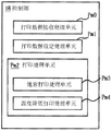
Fig. 1 is the control block diagram of the print system in the 1st embodiment of the present invention.
Fig. 2 is the block diagram that the details of the control part in the 1st embodiment of the present invention are shown.
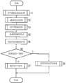
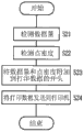
Fig. 3 is the flow chart that the action of the printer in the 1st embodiment of the present invention is shown.
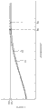
Fig. 4 is the figure that impacts characteristic illustrating in the 1st embodiment of the present invention.
Fig. 5 is the control block diagram of the print system in the 2nd embodiment of the present invention.
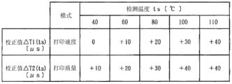
Fig. 6 is the figure of example that the corrected value of the voltage application time in the 2nd embodiment of the present invention is shown.
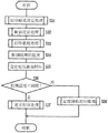
Fig. 7 is the flow chart that the action of the printer in the 2nd embodiment of the present invention is shown.
Fig. 8 is the control block diagram of the print system in the 3rd embodiment of the present invention.
Fig. 9 is the flow chart that the action of the printer driver in the 3rd embodiment of the present invention is shown.
Figure 10 is the flow chart that the action of the printer in the 3rd embodiment of the present invention is shown.
Figure 11 is the control block diagram of the print system in the 4th embodiment of the present invention.
Figure 12 is the flow chart that the action of the printer in the 4th embodiment of the present invention is shown.
Label declaration
10: printer; 21: printhead; 23: coil; 27: coil drive portion; 28: temperature detecting part; 32: Threshold portion; 33: print conditions configuration part; T, T1, T2: voltage application time; Ts: detected temperatures; τ 1, τ 2: threshold value.
The specific embodiment
Below, the embodiment that present invention will be described in detail with reference to the accompanying.In this case, the printer as printing equipment is described.
Fig. 1 is the control block diagram of the print system in the 1st embodiment of the present invention.
In figure, the 10th, printer, the 11st, as the master computer of epigyny device, Nw connects printer 10 and master computer 11 and the network that forms print system, and master computer 11 has the printer driver 12 as printer action handling part in order to make printer 10 actions.Via described network N w, from master computer 11, to printer 10, send print data, from printer 10 to master computer 11, send the status information of the state that represents printer 10.
And, the 16th, print the control part that the integral body of machine 10 is controlled, the 18th, in printer 10, on scanning direction, move freely the bracket setting, the 19th, for making this bracket 18 along the tray motor with drive division as traveling of not shown bracket axle traveling, the 21st, carry the printhead on described bracket 18.
This printhead 21 has the print needle 22 as a plurality of type elements, according to print data, makes each print needle 22 not shown ink ribbon of optionally before coming in to impact, and the China ink of ink ribbon is transferred in the paper using of medium, thereby prints.
For this reason, in described printhead 21, be equipped with the iron core that quantity is identical with print needle 22, corresponding to this each iron core, swing and be equipped with freely the not shown armature that front end is provided with described print needle 22.And by applying predetermined voltage and provide drive current to coil 23 to being provided in each iron core coil 23 around, when making each iron core produce electromagnetic force, armature is attracted by iron core, print needle 22 is driven and advance.Coil 23 is equivalent to the driver part in the present invention.
And, in described printhead 21, be closely equipped with the internal temperature for detection of printhead 21 with coil 23, be the thermistor 24 as temperature detection key element of the temperature of coil 23 in the present embodiment.
Described control part 16 with as motor, drive the motor driving part 26 of processing unit, coil drive portion 27 as coil drive processing unit, temperature detecting part 28 connections such as grade as temperature detection processing unit, described motor driving part 26 receives motor drive signal and driven bracket motor 19 from control part 16, coil drive portion 27 drives signal and applies voltage to coil 23 from control part 16 receiving coils, thereby provide drive current to coil 23, temperature detecting part 28 is according to the temperature of the resistance variations magnetic test coil 23 of thermistor 24, as detected temperatures ts, send to control part 16.Coil drive portion 27 is equivalent to the driving element drive division in the present invention.
And, control part 16 and print data handling part 31 as print data processing unit, as Threshold processing unit and as the Threshold portion 32 of the 1st data maintaining part, set processing unit and as the print conditions configuration part 33 of the 2nd data maintaining part, set processing unit and be connected as the voltage application time configuration part 34 of the 3rd data maintaining part etc. as voltage application time as print conditions.
Described print data handling part 31 receives the print data sending from master computer 11, the print data receiving is recorded in and in not shown buffer, carries out buffer memory, and convert described print data to layout for printing, i.e. the layout for each print needle 22 is advanced with predetermined pattern.
And described Threshold portion 32 is for the temperature of control coil 23, select and set a plurality ofly, be the predetermined threshold in two threshold values (the 1st threshold value of high-temperature region, the 2nd threshold value) τ 1, τ 2 in the present embodiment.
In the present embodiment, in printer 10, be set with the print quality mode of priority that makes the print speed mode of priority of conduct the 1st printing model that print speed preferentially prints and make conduct the 2nd printing model that print quality preferentially prints, when setting print speed mode of priority, set a little threshold tau 1 of height for the temperature of control coil 23, when setting print quality mode of priority, set the lower threshold tau 2 for the temperature of control coil 23.
In this case, a reference value of establishing threshold value is s, establishes positive integer while being α, and threshold tau 1 becomes
τ1=s
Threshold tau 2 becomes
τ2=s-α
In addition, in the present embodiment, threshold tau 1 be 110 ℃ ], and threshold tau 2 be 100 ℃ ].
And the threshold value (hereinafter referred to as " setting threshold ") of setting in the described detected temperatures ts in 33 pairs of described print conditions configuration parts and threshold tau 1, τ 2 compares, according to comparative result, set the print conditions that drives printhead 21, send it to control part 16.; print conditions configuration part 33 is at described detected temperatures ts lower than setting threshold in the situation that; the print conditions of established standards, is setting threshold above in the situation that at described detected temperatures ts, sets the temperature reduction print conditions for reducing the temperature of coil 23.
In addition, in the present embodiment, the printing of the print conditions of standard for carrying out with the print load of standard controlling based on common printing, print speed by standard, the formations such as the line feed amount of standard, temperature reduces with print conditions for carrying out the printing based on thermal control with the print load less than the print load of standard, in order to drive off and on printhead 21 or to make bracket 18 only move to drive printhead 21 to a direction, by the instruction for the driving of printhead 21 is stopped, the print speed lower than the print speed of standard, the printing Segmentation Number of cutting apart manyly than the printing Segmentation Number of standard forms.
And described voltage application time configuration part 34 and detected temperatures ts establish accordingly directional coil 23 to execute the alive time are voltage application time T.In this case, detected temperatures ts is lower, and voltage application time T is set shortlyer, and detected temperatures ts is higher, and voltage application time T is set longlyer.
Described voltage application time T is by making fixed value T0 add correction value delta T(ts) represent to become
T=T0+ΔT(ts)
Described correction value delta T(ts) with impact force F, do not follow detected temperatures ts to change and the mode that changes becomes the function of detected temperatures ts, detected temperatures ts is lower less, and detected temperatures ts is higher larger.In the present embodiment, correction value delta T(ts) according to each temperature province of detected temperatures ts, set, at detected temperatures ts less than 40 ℃ ] and time be made as 0 [ μ s ], at detected temperatures ts, be 40 ℃ ] more than and less than 60 ℃ ] time be made as+10 [ μ s ], at detected temperatures ts, be 60 ℃ ] more than and less than 80 ℃ ] time be made as+20 [ μ s ], at detected temperatures ts, be 80 ℃ ] more than and less than 100 ℃ ] time be made as+30 [ μ s ], at detected temperatures ts, be 100 ℃ ] be made as+40 [ μ s ] when above.
Below, the action of described print system is described.
Fig. 2 is the block diagram that the details of the control part in the 1st embodiment of the present invention are shown, and Fig. 3 is the flow chart that the action of the printer in the 1st embodiment of the present invention is shown.
First, the print data reception & disposal unit Pm0 of control part 16 prints data receiver and processes, and receives the print data sending from master computer 11, is recorded in and in described buffer, carries out buffer memory.
Then, the printing model of control part 16 is set processing unit Pm1 and is printed pattern setting processing, reads and analyze the instruction comprising in print data, sets the printing model of print speed mode of priority or print quality mode of priority.In addition, when operator selects printing model by printer driver 12 on master computer 11, in the beginning additional representation of print data, selected the instruction of print speed mode of priority or print quality mode of priority.
In the present embodiment, operator selects printing model on master computer 11, printing model is set processing unit Pm1, by analyzing the instruction comprising in print data, printer 10 is set to printing model, yet the not shown operating portion that operator also can be provided in printer 10 by operation is directly set printing model to printer 10.
Then, the 32(Fig. 1 of Threshold portion) carry out Threshold processing, read in the printing model that printer 10 is set, according to this printing model, setting threshold is set, this setting threshold is sent to control part 16.
Then, described print data handling part 31 is read print data from described buffer, converts print data to layout for each print needle 22 is advanced with predetermined pattern.
Then, described temperature detecting part 28 carries out temperature detection processing, according to the temperature of the resistance variations magnetic test coil 23 of thermistor 24, as detected temperatures ts, send to control part 16, described voltage application time configuration part 34 is carried out voltage application time and is set processing, read in detected temperatures ts, set the voltage application time T corresponding with this detected temperatures ts.
Then, the print process unit Pm2 of described control part 16 prints, read in detected temperatures ts and setting threshold, judge that whether detected temperatures ts is lower than setting threshold, at detected temperatures ts, lower than setting threshold in the situation that, the common print process unit Pm3 of print process unit Pm2 carries out common print processing, reads in the print conditions of the standard of being set by print conditions configuration part 33, print conditions with this standard drives printhead 21, conventionally prints.In addition, at detected temperatures ts, lower than setting threshold in the situation that, along with detected temperatures, ts increases, and voltage application time T extends, and produces certain impact force F.
And, at detected temperatures ts, be that setting threshold is above in the situation that, the temperature of print process unit Pm2 reduces print process unit Pm4 and carries out temperature reduction print processing, read in the temperature reduction print conditions of being set by print conditions configuration part 33, with temperature, reduce with print conditions and drive printhead 21, carry out temperature and reduce printing.
Below, the characteristic that impacts of printhead 21 is described.
Fig. 4 is the figure that impacts characteristic illustrating in the 1st embodiment of the present invention.In addition, in figure, application time T is pressed in transverse axis power taking, and the longitudinal axis is got impact force F.
In figure, line L1 is illustrated in and sets print speed mode of priority, setting threshold τ 1, control the driving of printhead 21 so that the voltage application time T of detected temperatures ts while becoming threshold tau 1 and the relation of impact force F, line L2 is illustrated in and sets print quality mode of priority, setting threshold τ 2, controls the driving of printhead 21 so that the voltage application time T of detected temperatures ts while becoming threshold tau 2 and the relation of impact force F.
The in the situation that of setting threshold τ 2, when voltage application time T is made as to Tb, can be created in and under print quality mode of priority, prints needed impact force F2.On the other hand, the in the situation that of setting threshold τ 1, when voltage application time T is extended, become Ta(> Tb) time, can be created in and under print speed mode of priority, print needed impact force F1(< F2), yet, even if voltage application time T is longer than Ta, also cannot produce impact force F2.
Like this, in the present embodiment, when setting threshold τ 2, such as the print data generating according to word, image in order to form high-resolution etc., document to common paper etc. carries out in the situation of high-quality printing, can fully increase impact force F, thereby gradation of drop-out colour do not reduce, print quality does not reduce.
And, when setting threshold τ 1, such as will be according to the print data generating in order to form such common words such as text data, bill to continuous paper etc. is carried out in the situation of flying print, without coil 23 is maintained to lower temperature, thereby can to shorten for the temperature of coil 23 is maintained compared with low temperature be time out from stopping applying voltage to coil 23 to again executing the alive time to coil 23.Therefore, print speed does not reduce.And even in the situation that the data volume of print data increases or dot density increases, the handling capacity of printer 10 does not reduce yet.
As a result, can, according to operator to requirement of the kind of print data, paper using form etc., with suitable print quality, suitable print speed, print.
Below, flow chart is described.
Step S1 printing model is set processing unit Pm1 and is printed pattern setting processing.
Step S2 Threshold portion 32 carries out Threshold processing.
Step S3 print data handling part 31 prints data processing.
The temperature of step S4 temperature detecting part 28 magnetic test coils 23.
Step S5 voltage application time configuration part 34 setting voltage application time T.
Step S6 print process unit Pm2 judges that whether detected temperatures ts is lower than setting threshold.At detected temperatures ts, lower than setting threshold in the situation that, entering step S7, is setting threshold above in the situation that at detected temperatures ts, enters step S8.
The common print process unit Pm3 of step S7 carries out common print processing, end process.
Step S8 temperature reduces print process unit Pm4 and carries out temperature reduction print processing, end process.
In addition, in the present embodiment, detected temperatures ts is lower, voltage application time T is just shorter, detected temperatures ts is higher, voltage application time T is just longer, yet no matter be in the situation that setting print quality mode of priority or in the situation that setting print speed mode of priority, correction value delta T(ts due to voltage application time T) equate, thereby in the situation that setting print speed mode of priority, correction value delta T(ts) excessively increase result, voltage application time T extends, and the handling capacity of printer 10 reduces.
Therefore,, in the situation that setting print speed mode of priority, do not make the 2nd embodiment of the present invention of the handling capacity reduction of printer 10 describe.In addition, for the part having with the 1st embodiment same structure, give same numeral, for the invention effect that there is same structure and bring, quote the effect of identical embodiment.
Fig. 5 is the control block diagram of the print system in the 2nd embodiment of the present invention, and Fig. 6 is the figure of example that the corrected value of the voltage application time in the 2nd embodiment of the present invention is shown.
In Fig. 5, the 45th, as the 1st voltage application time, set processing unit and as the 1st voltage application time configuration part of the 1st data maintaining part, the 46th, as the 2nd voltage application time, set processing unit and as the 2nd voltage application time configuration part of the 2nd data maintaining part.Described the 1st voltage application time configuration part 45 is when setting print speed mode of priority, during setting threshold τ 1, set the 1st voltage application time T1 corresponding with detected temperatures ts, the 2nd voltage application time configuration part 46 is when setting print quality mode of priority, during setting threshold τ 2, set the 2nd voltage application time T2 corresponding with detected temperatures ts.
Therefore, detected temperatures ts is read in the 1st voltage application time configuration part 45, and the 1st voltage application time T1 is sent to control part 16.And detected temperatures ts is read in the 2nd voltage application time configuration part 46, the 2nd voltage application time T2 is sent to control part 16.
In the present embodiment, correction value delta T1(ts during each detected temperatures ts) be less than correction value delta T2(ts), the 1st voltage application time T1 during each detected temperatures ts is lower than the 2nd voltage application time T2.
Described the 1st voltage application time T1 is by making fixed value T0 add correction value delta T1(ts) represent to become
T1=T0+ΔT1(ts)
With impact force F, do not follow detected temperatures ts to change and the mode of variation,, even change with detected temperatures ts, also in the time of producing detected temperatures ts and equal threshold tau 1, be in the present embodiment detected temperatures ts be 110 ℃ ] and time the mode of impact force F, by described correction value delta T1(ts) be made as the function of detected temperatures ts, detected temperatures ts is lower less, and detected temperatures ts is higher larger.In the present embodiment, correction value delta T1(ts) at detected temperatures ts less than 60 ℃ ] and time be made as 0 [ μ s ], at detected temperatures ts, be 60 ℃ ] more than and less than 80 ℃ ] time be made as+10 [ μ s ], at detected temperatures ts, be 80 ℃ ] more than and less than 100 ℃ ] time be made as+20 [ μ s ], at detected temperatures ts, be 100 ℃ ] more than and less than 110 ℃ ] time be made as+30 [ μ s ], at detected temperatures ts, be 110 ℃ ] be made as+40 [ μ s ] when above.
And described the 2nd voltage application time T2 is by making fixed value T0 add correction value delta T2(ts) represent to become
T2=T0+ΔT2(ts)
Even change with detected temperatures ts, also in the time of producing detected temperatures ts and equal threshold tau 2, be in the present embodiment detected temperatures ts be 100 ℃ ] and time the mode of impact force F, by described correction value delta T2(ts) be made as the function of detected temperatures ts, detected temperatures ts is lower less, and detected temperatures ts is higher larger.In the present embodiment, correction value delta T2(ts) at detected temperatures ts less than 40 ℃ ] and time be made as 0 [ μ s ], at detected temperatures ts, be 40 ℃ ] more than and less than 60 ℃ ] time be made as+10 [ μ s ], at detected temperatures ts, be 60 ℃ ] more than and less than 80 ℃ ] time be made as+20 [ μ s ], at detected temperatures ts, be 80 ℃ ] more than and less than 100 ℃ ] time be made as+30 [ μ s ], at detected temperatures ts, be 100 ℃ ] be made as+40 [ μ s ] when above.
Below, the action of print system is described.
Fig. 7 is the flow chart that the action of the printer in the 2nd embodiment of the present invention is shown.
First, print data reception & disposal unit Pm0(Fig. 2 of control part 16) receive the print data sending from master computer 11, be recorded in and in described buffer, carry out buffer memory.
Then, the printing model of control part 16 is set processing unit Pm1 and is read and analyze the instruction comprising in print data, sets the printing model of print speed mode of priority or print quality mode of priority.
Then, as the Threshold portion 32 of Threshold processing unit, read in the printing model that printer 10 is set, according to this printing model, setting threshold is set, this setting threshold is sent to control part 16.
Then, as the print data handling part 31 of described print data processing unit, from described buffer, read print data, convert print data to layout.
Then, as the described temperature detecting part 28 of temperature detection processing unit, according to the temperature of the resistance variations magnetic test coil 23 of the thermistor 24 as temperature detection key element, as detected temperatures ts, send to control part 16.
Then, the not shown printing model judgement processing unit of described control part 16 prints mode decision and processes, and judges whether that by printing model, setting processing unit Pm1 has set print speed mode of priority.Then, in the situation that having set described print speed mode of priority, detected temperatures ts is read in described the 1st voltage application time configuration part 45, set the 1st voltage application time T1 corresponding with this detected temperatures ts, in the situation that not setting described print speed mode of priority (in the situation that having set described print quality mode of priority), detected temperatures ts is read in described the 2nd voltage application time configuration part 46, sets the 2nd voltage application time T2 corresponding with this detected temperatures ts.
Then, the print process unit Pm2 of described control part 16 reads in detected temperatures ts and setting threshold, judge that whether detected temperatures ts is lower than setting threshold, at detected temperatures ts lower than setting threshold in the situation that, the common print process unit Pm3 of print process unit Pm2 reads in the print conditions of the standard of being set by the print conditions configuration part 33 of setting processing unit as print conditions, print conditions with this standard drives printhead 21, conventionally prints.And, at detected temperatures ts, be that setting threshold is above in the situation that, the temperature of print process unit Pm2 reduces print process unit Pm4 and reads in the temperature reduction print conditions of being set by print conditions configuration part 33, with this temperature, reduces with print conditions and carries out temperature reduction printing.
Like this, in the present embodiment, because the 2nd voltage application time T2 that has set the 1st voltage application time T1 in the situation of print speed mode of priority than in the situation of having set print quality mode of priority is short, thereby can reduce the temperature of coil 23.Therefore, can not shorten and execute alive time out to coil 23, thereby the handling capacity of printer 10 can not reduce.
Below, flow chart is described.
Step S11 printing model is set processing unit Pm1 and is printed pattern setting processing.
Step S12 Threshold portion 32 carries out Threshold processing.
Step S13 print data handling part 31 prints data processing.
The temperature of step S14 temperature detecting part 28 magnetic test coils 23.
Step S15 printing model judgement processing unit judges whether to have set print speed mode of priority.In the situation that having set print speed mode of priority, enter step S16, in the situation that not setting print speed mode of priority, enter step S17.
Step S16 sets the 1st voltage application time T1 in the 1st voltage application time configuration part 45.
Step S17 sets the 2nd voltage application time T2 in the 2nd voltage application time configuration part 46.
Step S18 print process unit Pm2 judges that whether detected temperatures ts is lower than setting threshold.At detected temperatures ts, lower than setting threshold in the situation that, entering step S19, is setting threshold above in the situation that at detected temperatures ts, enters step S20.
The common print process unit Pm3 of step S19 carries out common print processing, end process.
Step S20 temperature reduces print process unit Pm4 and carries out temperature reduction print processing, end process.
Below, to automatically set the 3rd embodiment of the present invention of the printing model of printhead 21 according to the print data sending from master computer 11, describe.In addition, for having with the 1st, the part of the 2nd embodiment same structure, give same numeral, for the invention effect that there is same structure and bring, quote the effect of identical embodiment.
Fig. 8 is the control block diagram of the print system in the 3rd embodiment of the present invention.
In this case, in the master computer 11 as epigyny device, according to print data, calculating the load impose on printhead 21 is print load, in printer 10, sets the printing model of printhead 21 according to print load.
For this reason, as the printer driver 12 of printer driver section, have as detecting as the 1st print load calculation processing unit of the data volume δ of the print data of the 1st print load and as the data volume test section 48 of data volume Check processing unit, and as detecting as the 2nd print load calculation processing unit of the dot density ρ of the print data of the 2nd print load and as the dot density test section 49 of dot density Check processing unit, to as additional data, append to the beginning of print data by the detected data volume δ of described data volume test section 48 with by the detected dot density ρ of dot density test section 49, send to printer 10.
Then, in described printer 10, when receiving the print data sending from master computer 11, described printing model is set processing unit Pm1(Fig. 2) read data volume δ and the dot density ρ of print data, according to data volume δ and dot density ρ, set print speed mode of priority or print quality mode of priority.
Below, the action of print system is described.
Fig. 9 is the flow chart that the action of the printer driver in the 3rd embodiment of the present invention is shown, and Figure 10 is the flow chart that the action of the printer in the 3rd embodiment of the present invention is shown.
In this case, in described master computer 11, described data volume test section 48 carries out the data volume Check processing as the 1st print load computing, reads in print data, detects the data volume δ of print data.And described dot density test section 49 carries out the dot density Check processing as the 2nd print load computing, reads in print data, detect the dot density ρ of print data.
Then, the not shown print data transmission processing unit of described master computer 11 prints data sending processing, appends to the beginning of print data using data volume δ and dot density ρ as additional data.
Then, in described printer 10, print data reception & disposal unit Pm0(Fig. 2 of control part 16) receive the print data sending from master computer 11, be recorded in and in buffer, carry out buffer memory.
Then, the printing model of control part 16 is set data volume δ and the dot density ρ that processing unit Pm1 read and analyzed print data, sets the printing model of print speed mode of priority or print quality mode of priority.
In addition, many or dot density ρ is high at the data volume δ of print data, thus in the large situation of print load, when the temperature of coil 23 is high, impact force F reduces.
Therefore, described printing model is set processing unit Pm1 and whether more than threshold value δ th and dot density ρ, whether higher than threshold value ρ th, is judged whether print load condition is set up according to data volume δ, at data volume δ more than threshold value δ th and dot density ρ higher than threshold value ρ th in the situation that, being judged as print load condition sets up, in the situation that print load condition is set up, set print speed mode of priority, at data volume δ, be below threshold value δ th or dot density ρ is below threshold value ρ th, in the invalid situation of print load condition, set print quality mode of priority.
Then, the printing model that printer 10 is set is read in Threshold portion 32, according to this printing model, setting threshold is set, and this setting threshold is sent to control part 16.
Then, as the described print data handling part 31 of print data processing unit, from described buffer, read print data, convert print data to layout.
Then, described temperature detecting part 28 is according to the temperature of the resistance variations magnetic test coil 23 of thermistor 24, as detected temperatures ts, send to control part 16, detected temperatures ts is read in the described voltage application time configuration part 34 of setting processing unit as voltage application time, sets the voltage application time T corresponding with this detected temperatures ts.
Then, the print process unit Pm2 of described control part 16 reads in detected temperatures ts and setting threshold, judge that whether detected temperatures ts is lower than setting threshold, at detected temperatures ts lower than setting threshold in the situation that, the common print process unit Pm3 of print process unit Pm2 reads in the print conditions of the standard of being set by print conditions configuration part 33, print conditions with this standard drives printhead 21, conventionally prints.And, at detected temperatures ts, be that setting threshold is above in the situation that, the temperature of print process unit Pm2 reduces print process unit Pm4 and reads in the temperature reduction print conditions of being set by print conditions configuration part 33, with temperature, reduces with print conditions and carries out temperature reduction printing.
Like this, in the present embodiment, high in the print load that imposes on printhead 21, in the situation that print load condition is set up, set print speed mode of priority, low in the print load that imposes on printhead 21, in the invalid situation of print load condition, set print quality mode of priority, thereby when more than the data volume δ of print data or when dot density ρ is high, set print speed mode of priority, setting threshold τ 1, can extend voltage application time T.Therefore, impact force F can not reduce, and print quality can not reduce.
And, owing to printing higher than the print data of threshold value ρ th for dot density ρ, thereby can suppress print quality change.
And owing to automatically setting printing model according to print load, thereby operator is without the setting that prints pattern.
Below, the flow chart of Fig. 9 is described.
Step S21 data volume test section 48 detects data volume δ.
Step S22 dot density test section 49 test point density p.
Step S23 print data transmission processing unit appends to the beginning of print data using data volume δ and dot density ρ as additional data.
Step S24 print data transmission processing unit sends to printer 10 by print data.
Below, the flow chart of Figure 10 is described.
Step S31 printing model is set processing unit Pm1 and is printed pattern setting processing.
Step S32 Threshold portion 32 carries out Threshold processing.
Step S33 print data handling part 31 prints data processing.
The temperature of step S34 temperature detecting part 28 magnetic test coils 23.
Step S35 voltage application time configuration part 34 setting voltage application time T.
Step S36 print process unit Pm2 judges that whether detected temperatures ts is lower than setting threshold.At detected temperatures ts, lower than setting threshold in the situation that, entering step S37, is setting threshold above in the situation that at detected temperatures ts, enters step S38.
The common print process unit Pm3 of step S37 carries out common print processing, end process.
Step S38 temperature reduces print process unit Pm4 and carries out temperature reduction print processing, end process.
Below, to automatically set the 4th embodiment of the present invention of printing model according to the print data sending from master computer 11, describe.In addition, for the part having with the 1st~3rd embodiment same structure, give same numeral, for the invention effect that there is same structure and bring, quote the effect of identical embodiment.
Figure 11 is the control block diagram of the print system in the 4th embodiment of the present invention.
In figure, the 45th, as the 1st voltage application time, set processing unit and as the 1st voltage application time configuration part of the 1st data maintaining part, the 46th, as the 2nd voltage application time, set processing unit and as the 2nd voltage application time configuration part of the 2nd data maintaining part, described the 1st voltage application time configuration part 45 is when setting print speed mode of priority, during setting threshold τ 1, set the 1st voltage application time T1 corresponding with detected temperatures ts, the 2nd voltage application time configuration part 46 is when setting print quality mode of priority, during setting threshold τ 2, set the 2nd voltage application time T2 corresponding with detected temperatures ts.
Therefore, in the 1st voltage application time configuration part 45, corresponding to detected temperatures ts, record the 1st voltage application time T1, detected temperatures ts is read in described the 1st voltage application time configuration part 45, and the 1st voltage application time T1 is sent to control part 16.And, in the 2nd voltage application time configuration part 46, corresponding to detected temperatures ts, recording the 2nd voltage application time T2, detected temperatures ts is read in described the 2nd voltage application time configuration part 46, and the 2nd voltage application time T2 is sent to control part 16.
And, in the master computer 11 as epigyny device, according to print data, calculate the print load that imposes on printhead 21, in printer 10, according to print load, set printing model.
Therefore, as the printer driver 12 of printer driver section, have as detecting as the 1st print load calculation processing unit of the data volume δ of the print data of the 1st print load and as the data volume test section 48 of data volume Check processing unit, and as detecting as the 2nd print load calculation processing unit of the dot density ρ of the print data of the 2nd print load and as the dot density test section 49 of dot density Check processing unit, to as additional data, append to the beginning of print data by the detected data volume δ of described data volume test section 48 with by the detected dot density ρ of dot density test section 49, send to printer 10.
Then, in this printer 10, when receiving the print data sending from master computer 11, described printing model is set processing unit Pm1(Fig. 2) read data volume δ and the dot density ρ of print data, according to data volume δ and dot density ρ, set print speed mode of priority or print quality mode of priority.
Below, the action of print system is described.In addition, because the action of the master computer 11 in the 4th embodiment is identical with the 3rd embodiment, thereby description thereof is omitted.
Figure 12 is the flow chart that the action of the printer in the 4th embodiment of the present invention is shown.
In printer 10, print data reception & disposal unit Pm0(Fig. 2 of control part 16) receive the print data sending from master computer 11, be recorded in and in buffer, carry out buffer memory.
Then, the printing model of control part 16 is set data volume δ and the dot density ρ that processing unit Pm1 read and analyzed print data, sets the printing model of print speed mode of priority or print quality mode of priority.
; described printing model is set processing unit Pm1 and whether more than threshold value δ th and dot density ρ, whether higher than threshold value ρ th, is judged whether print load condition is set up according to data volume δ; at data volume δ more than threshold value δ th and dot density ρ higher than threshold value ρ th; in the situation that print load condition is set up; set print speed mode of priority; at data volume δ, be below threshold value δ th or dot density ρ is below threshold value ρ th; in the invalid situation of print load condition, set print quality mode of priority.
Then, as the Threshold portion 32 of Threshold processing unit, read in the printing model that printer 10 is set, according to this printing model, setting threshold is set, this setting threshold is sent to control part 16.
Then, as the described print data handling part 31 of print data processing unit, from described buffer, read print data, convert print data to layout.
Then, as the described temperature detecting part 28 of temperature detection processing unit, according to the temperature of the resistance variations magnetic test coil 23 of the thermistor 24 as temperature detection key element, as detected temperatures ts, send to control part 16.
Then, the described printing model judgement processing unit of described control part 16 determines whether that by printing model, setting processing unit Pm1 has set print speed mode of priority.Then, in the situation that having set print speed mode of priority, detected temperatures ts is read in described the 1st voltage application time configuration part 45, set the 1st voltage application time T1 corresponding with this detected temperatures ts, in the situation that not setting print speed mode of priority, detected temperatures ts is read in described the 2nd voltage application time configuration part 46, sets the 2nd voltage application time T2 corresponding with this detected temperatures ts.
Then, the print process unit Pm2 of described control part 16 reads in detected temperatures ts and setting threshold, judge that whether detected temperatures ts is lower than setting threshold, at detected temperatures ts lower than setting threshold in the situation that, the common print process unit Pm3 of print process unit Pm2 reads in the print conditions of the standard of being set by print conditions configuration part 33, print conditions with this standard drives printhead 21, conventionally prints.And, at detected temperatures ts, be that setting threshold is above in the situation that, the temperature of print process unit Pm2 reduces print process unit Pm4 and reads in the temperature reduction print conditions of being set by print conditions configuration part 33, with temperature, reduces with print conditions and carries out temperature reduction printing.
Like this, in the present embodiment, set the 1st voltage application time T1 in the situation of print speed mode of priority shorter than the 2nd voltage application time T2 in the situation of having set print quality mode of priority, thereby can reduce the temperature of coil 23.Therefore, owing to can shortening, to coil 23, do not execute alive time out, thereby the handling capacity of printer 10 can not reduce.
And, high in the print load that imposes on printhead 21, in the situation that print load condition is set up, set print speed mode of priority, low in the print load that imposes on printhead 21, in the invalid situation of print load condition, set print quality mode of priority, thereby when more than the data volume δ of print data or when dot density ρ is high, set print speed mode of priority, setting threshold τ 1, can extend voltage application time T.Therefore, impact force F can not reduce, and print quality can not reduce.
And, owing to printing higher than the print data of threshold value ρ th for dot density ρ, thereby can suppress print quality change.
And owing to automatically setting printing model according to print load, thereby operator is without the setting that prints pattern.
Below, flow chart is described.
Step S41 printing model is set processing unit Pm1 and is printed pattern setting processing.
Step S42 Threshold portion 32 carries out Threshold processing.
Step S43 print data handling part 31 prints data processing.
The temperature of step S44 temperature detecting part 28 magnetic test coils 23.
Step S45 printing model judgement processing unit judges whether to have set print speed mode of priority.In the situation that having set print speed mode of priority, enter step S46, in the situation that not setting print speed mode of priority, enter step S47.
Step S46 sets the 1st voltage application time T1 in the 1st voltage application time configuration part 45.
Step S47 sets the 2nd voltage application time T2 in the 2nd voltage application time configuration part 46.
Step S48 print process unit Pm2 judges that whether detected temperatures ts is lower than setting threshold.At detected temperatures ts, lower than setting threshold in the situation that, entering step S49, is setting threshold above in the situation that at detected temperatures ts, enters step S50.
The common print process unit Pm3 of step S49 carries out common print processing, end process.
Step S50 temperature reduces print process unit Pm4 and carries out temperature reduction print processing, end process.
In described the 3rd, the 4th embodiment, according to the data volume δ of print data, whether more than threshold value δ th and dot density ρ, whether higher than threshold value ρ th, judge whether print load condition is set up, at data volume δ, more than threshold value δ th or dot density ρ higher than threshold value ρ th in the situation that, can be judged as and print loading condiction and set up.
In addition,, except the needle type print head illustrating in above-mentioned the 1st embodiment~4th embodiment, the present invention can also be applied to have the LED print head of LED element, the first-class various printheads of thermal printing that consist of heating resistor as type element.Printing portion has thermistor, utilizes the temperature of printhead, controls LED element or heating resistor that electric current is provided from driving element drive division, thereby controls print speed and print quality.
In addition, the present invention is not limited to described each embodiment, can carry out various distortion according to aim of the present invention, and scope of the present invention is not got rid of these distortion.
Claims (15)
1. a printer, is characterized in that, described printer has:
Printhead, the driver part that it has type element and drives described type element;
Driving element drive division, it provides drive current to described driver part, drives described type element to print;
Temperature detecting part, it is for detection of the internal temperature of described printhead;
Threshold portion, it sets the 1st threshold value with printing model and accordingly than a threshold value in the 2nd low threshold value of the 1st threshold value, to control the internal temperature of printhead; And
Print conditions configuration part, it sets the print conditions for reducing the internal temperature of printhead in the situation that be that detected temperatures is served as reasons more than the threshold value that described Threshold portion sets by the internal temperature of the detected printhead of described temperature detecting part.
2. printer according to claim 1, wherein,
Described printing model is to make print speed the 1st printing model preferentially printing and the 2nd printing model that print quality is preferentially printed,
Described Threshold portion sets the 1st threshold value when having set the 1st printing model, sets the 2nd threshold value when having set the 2nd printing model.
3. printer according to claim 1 and 2, wherein, described printer has voltage application time configuration part, and this voltage application time configuration part and described detected temperatures are set accordingly to described driver part and are executed alive voltage application time.
4. printer according to claim 3, wherein, detected temperatures is lower, and described voltage application time configuration part is set shortlyer by voltage application time, and detected temperatures is higher, and described voltage application time configuration part is set longlyer by voltage application time.
5. according to the printer described in any one in claim 1~4, wherein, described printer has printing model and sets processing unit, and this printing model is set processing unit and set described printing model according to the instruction sending from epigyny device.
6. according to the printer described in any one in claim 1~4, wherein, described printer has printing model and sets processing unit, and this printing model is set processing unit and to being equipped on the operation of the operating portion of printer, set described printing model according to operator.
7. according to the printer described in any one in claim 1~4, wherein, described printer has printing model and sets processing unit, and this printing model is set processing unit and set described printing model according to the data volume of print data and the dot density of print data that send from epigyny device.
8. printer according to claim 1, wherein, described driver part is coil.
9. a printer, is characterized in that, described printer has:
Printhead, the driver part that it has type element and drives described type element;
Driving element drive division, it provides drive current to described driver part, drives described type element to print;
Temperature detecting part, it is for detection of the internal temperature of described printhead;
Threshold portion, it sets the 1st threshold value with printing model and accordingly than a threshold value in the 2nd low threshold value of the 1st threshold value, to control the internal temperature of printhead;
Voltage application time configuration part, its with by the internal temperature of the detected printhead of described temperature detecting part, be detected temperatures accordingly, set and execute alive voltage application time to described driver part; And
Print conditions configuration part, it more than the threshold value that described Threshold portion sets in the situation that described detected temperatures is served as reasons sets the print conditions for reducing the internal temperature of printhead,
Voltage application time under each detected temperatures when utilizing described the 1st threshold value to control the internal temperature of printhead of described voltage application time configuration part, sets to such an extent that the voltage application time under Billy's each detected temperatures during with the internal temperature of described the 2nd threshold value control printhead is short.
10. printer according to claim 9, wherein, the voltage application time under each detected temperatures is set in described voltage application time configuration part, the impact force when making it possible to produce detected temperatures and equating with threshold value.
11. printers according to claim 9, wherein, described driver part is coil.
Printhead driving method in 12. 1 kinds of printers, described printer has: printhead, the driver part that it has type element and drives described type element; And driving element drive division, it provides drive current to driver part, drives described type element to print, it is characterized in that, and in described printhead driving method,
Detect the internal temperature of printhead;
Set accordingly the 1st threshold value with printing model and than a threshold value in the 2nd low threshold value of the 1st threshold value, to control the internal temperature of printhead; And
In the situation that the internal temperature of detected printhead is detected temperatures, be more than the threshold value setting, set the print conditions for reducing the internal temperature of printhead.
13. printhead driving methods according to claim 12, wherein, described driver part is coil.
Printhead driving method in 14. 1 kinds of printers, described printer has: printhead, the driver part that it has type element and drives described type element; And driving element drive division, it provides drive current to driver part, drives described type element to print, it is characterized in that, and in described printhead driving method,
Detect the internal temperature of printhead;
Set accordingly the 1st threshold value with printing model and than a threshold value in the 2nd low threshold value of the 1st threshold value, to control the internal temperature of printhead;
With the internal temperature of detected printhead be detected temperatures accordingly, set and execute alive voltage application time to described driver part; And
In the situation that more than the threshold value that described detected temperatures is described setting, set the print conditions for reducing the internal temperature of printhead,
Voltage application time under each detected temperatures while utilizing described the 1st threshold value to control the internal temperature of printhead, is set to such an extent that the voltage application time under Billy's each detected temperatures during with the internal temperature of described the 2nd threshold value control printhead is short.
15. printhead driving methods according to claim 14, wherein, described driver part is coil.
Applications Claiming Priority (2)
| Application Number | Priority Date | Filing Date | Title |
|---|---|---|---|
| JP2012218385A JP2014069481A (en) | 2012-09-28 | 2012-09-28 | Printer and method for driving print-head |
| JP2012-218385 | 2012-09-28 |
Publications (1)
| Publication Number | Publication Date |
|---|---|
| CN103707662A true CN103707662A (en) | 2014-04-09 |
Family
ID=50401169
Family Applications (1)
| Application Number | Title | Priority Date | Filing Date |
|---|---|---|---|
| CN201310430860.4A Pending CN103707662A (en) | 2012-09-28 | 2013-09-22 | Printer and printer head driving method |
Country Status (2)
| Country | Link |
|---|---|
| JP (1) | JP2014069481A (en) |
| CN (1) | CN103707662A (en) |
Cited By (3)
| Publication number | Priority date | Publication date | Assignee | Title |
|---|---|---|---|---|
| CN105281404A (en) * | 2015-10-26 | 2016-01-27 | 国家电网公司 | Reliable printing method for hand-held electric (point-of-sale) POS terminal in condition of low battery voltage |
| CN106541718A (en) * | 2016-10-08 | 2017-03-29 | 南京富士通电子信息科技股份有限公司 | Suitable for the method for the photoelectric sensor threshold voltage adjust automatically of impact printer |
| CN107835329A (en) * | 2016-09-15 | 2018-03-23 | 柯尼卡美能达株式会社 | Image processing system |
Citations (6)
| Publication number | Priority date | Publication date | Assignee | Title |
|---|---|---|---|---|
| JPS60115477A (en) * | 1983-11-29 | 1985-06-21 | Oki Electric Ind Co Ltd | Printing head driving system |
| JPH0361547A (en) * | 1989-07-31 | 1991-03-18 | Pfu Ltd | Dividing printing control system in serial dot impact printer |
| JPH0513749U (en) * | 1991-05-25 | 1993-02-23 | 株式会社新興製作所 | Printing pressure controller for printer |
| JPH0761001A (en) * | 1993-08-26 | 1995-03-07 | Tec Corp | Printing processing device |
| CN101121342A (en) * | 2006-08-08 | 2008-02-13 | 三星电子株式会社 | Apparatus to prevent overheating of a print head, and a method thereof |
| CN102152646A (en) * | 2009-12-25 | 2011-08-17 | 精工爱普生株式会社 | Recording head control method and dot impact printer |
Family Cites Families (1)
| Publication number | Priority date | Publication date | Assignee | Title |
|---|---|---|---|---|
| JP5402618B2 (en) * | 2009-12-25 | 2014-01-29 | セイコーエプソン株式会社 | Recording head control method and dot impact printer |
-
2012
- 2012-09-28 JP JP2012218385A patent/JP2014069481A/en active Pending
-
2013
- 2013-09-22 CN CN201310430860.4A patent/CN103707662A/en active Pending
Patent Citations (6)
| Publication number | Priority date | Publication date | Assignee | Title |
|---|---|---|---|---|
| JPS60115477A (en) * | 1983-11-29 | 1985-06-21 | Oki Electric Ind Co Ltd | Printing head driving system |
| JPH0361547A (en) * | 1989-07-31 | 1991-03-18 | Pfu Ltd | Dividing printing control system in serial dot impact printer |
| JPH0513749U (en) * | 1991-05-25 | 1993-02-23 | 株式会社新興製作所 | Printing pressure controller for printer |
| JPH0761001A (en) * | 1993-08-26 | 1995-03-07 | Tec Corp | Printing processing device |
| CN101121342A (en) * | 2006-08-08 | 2008-02-13 | 三星电子株式会社 | Apparatus to prevent overheating of a print head, and a method thereof |
| CN102152646A (en) * | 2009-12-25 | 2011-08-17 | 精工爱普生株式会社 | Recording head control method and dot impact printer |
Cited By (4)
| Publication number | Priority date | Publication date | Assignee | Title |
|---|---|---|---|---|
| CN105281404A (en) * | 2015-10-26 | 2016-01-27 | 国家电网公司 | Reliable printing method for hand-held electric (point-of-sale) POS terminal in condition of low battery voltage |
| CN107835329A (en) * | 2016-09-15 | 2018-03-23 | 柯尼卡美能达株式会社 | Image processing system |
| CN106541718A (en) * | 2016-10-08 | 2017-03-29 | 南京富士通电子信息科技股份有限公司 | Suitable for the method for the photoelectric sensor threshold voltage adjust automatically of impact printer |
| CN106541718B (en) * | 2016-10-08 | 2018-11-30 | 南京富士通电子信息科技股份有限公司 | The method of photoelectric sensor threshold voltage adjust automatically suitable for stylus printer |
Also Published As
| Publication number | Publication date |
|---|---|
| JP2014069481A (en) | 2014-04-21 |
Similar Documents
| Publication | Publication Date | Title |
|---|---|---|
| US5477245A (en) | Temperatures control system for ink-jet recording apparatus | |
| CN103722907B (en) | Printer and control method thereof and device | |
| CN103707662A (en) | Printer and printer head driving method | |
| CN100553991C (en) | Double-side printer system and control method thereof | |
| JP5096904B2 (en) | Ink jet printer apparatus and ink jet printing method | |
| US8964225B2 (en) | Printing control method, printing control device and printing device with printing data printed according to height of another blank space | |
| JP2007164773A (en) | Image forming system, recorder for the system and image forming method | |
| JP2012116083A (en) | Bar code printing device | |
| JP2008100483A (en) | Head substrate, recording head, and recorder | |
| JP4799389B2 (en) | Head substrate, recording head, head cartridge, and recording apparatus | |
| JPS62263068A (en) | Impact-type printer | |
| CN201638013U (en) | Imaging box chip and imaging box with same | |
| CN107107624A (en) | Printer and method | |
| JP2007098828A (en) | Thermal printer, method for controlling energizing electricity and program | |
| JP2011152793A (en) | Image recording apparatus and method for controlling the same, and computer-readable storage medium | |
| CN201931736U (en) | Printer with self-reading function | |
| JP4282647B2 (en) | PRINT CONTROL DEVICE, PRINT CONTROL METHOD, AND THERMAL PRINTER | |
| US10518528B2 (en) | Printing control device, printing apparatus, control method of printing control device, and program | |
| JPS62113571A (en) | Recorder | |
| JP2985523B2 (en) | Printer | |
| CN108621609B (en) | Printing equipment and control method | |
| JP4411018B2 (en) | Recording device | |
| JP4877553B2 (en) | Printer apparatus and print control method used in the printer apparatus | |
| JP5917032B2 (en) | Ink jet recording apparatus and wiring method thereof | |
| JPH0635193B2 (en) | Printer |
Legal Events
| Date | Code | Title | Description |
|---|---|---|---|
| C06 | Publication | ||
| PB01 | Publication | ||
| C10 | Entry into substantive examination | ||
| SE01 | Entry into force of request for substantive examination | ||
| WD01 | Invention patent application deemed withdrawn after publication |
Application publication date: 20140409 |
|
| WD01 | Invention patent application deemed withdrawn after publication |