CN103645585A - Liquid crystal display - Google Patents
Liquid crystal display Download PDFInfo
- Publication number
- CN103645585A CN103645585A CN201310748817.2A CN201310748817A CN103645585A CN 103645585 A CN103645585 A CN 103645585A CN 201310748817 A CN201310748817 A CN 201310748817A CN 103645585 A CN103645585 A CN 103645585A
- Authority
- CN
- China
- Prior art keywords
- guide plate
- light guide
- fpc
- lcds
- lens
- Prior art date
- Legal status (The legal status is an assumption and is not a legal conclusion. Google has not performed a legal analysis and makes no representation as to the accuracy of the status listed.)
- Pending
Links
Images


Abstract
The invention relates to the technical field of computer peripherals, in particular to a liquid crystal display. The liquid crystal display comprises a backlight module, wherein the backlight module comprises a light guide plate, a glue frame and an FPC (Flexible circuit board) fixed on the glue frame, the light guide plate is sheathed in the glue frame, the FPC is arranged on the side surface of the light guide plate, a plurality of patch LEDs (Light emitting diodes) are arranged on the FPC, and a scattering lens is arranged between each patch LED and the light guide plate. According to the liquid crystal display, the patch LEDs are adopted to facilitate miniaturization of the size of the liquid crystal display, and besides, the scattering lens is arranged between each patch LED and the light guide plate, so that a light source entering the light guide plate is kept an area source.
Description
Technical field
The present invention relates to computer peripheral technical field, specifically, relate to a kind of LCDs.
Background technology
Along with scientific and technological development, LCDs is more and more thinner, more and more less; Especially the LCDs of mobile phone; In order to reach, make the LCDs of mobile phone become thinner, people constantly improve on liquid crystal display module, from before direct putting type develop into present side-light type, the light source of liquid crystal display module is set to the side of light guide plate; Owing to focusing on the optical design of liquid crystal display module always, make the development of LCDs enter into a bottleneck, can not further reduce the size of LCDs, the development of LCDs is hindered, therefore need to improve from other structures of LCDs.
Summary of the invention
The object of the invention is to solve the deficiencies in the prior art, a kind of LCDs is provided, the size of this LCDs is little, and cost is low.
For achieving the above object, the technical solution used in the present invention is:
A LCDs, comprises backlight module, and described backlight module comprises light guide plate, be enclosed within glue frame outside light guide plate, be fixed on the FPC of glue frame; FPC is arranged at the side of light guide plate, and FPC is provided with a plurality of paster LEDs, and is provided with dispersing lens between paster LED and light guide plate.
Further, also comprise diffusion sheet and prismatic lens, diffusion sheet is arranged at the exiting surface of light guide plate, prismatic lens is arranged at outside diffusion sheet, the exiting surface of described diffusion sheet is provided with many parallel raised lines, the exiting surface of described prismatic lens is also provided with many parallel raised lines, and the angle between the raised line extending direction on diffusion sheet and the extending direction of the raised line on prismatic lens is 75 to 90 degree.
Further, the side of described light guide plate is set to inclined-plane, the side laminating of FPC and light guide plate, and the back side of described light guide plate is provided with reflectance coating.
Further, the side of described light guide plate is provided with the shrinkage pool matching with paster LED; Paster LED stretches in described shrinkage pool.
Further, the bottom surface of described shrinkage pool is the curved surface of light diffusion.
Wherein, described curved surface is concave surface.Similar to the surface of recessed dispersing lens.Certainly, in shrinkage pool, also can be provided for the dispersing lens of light diffusion.
Wherein, the incidence surface of described dispersing lens is provided with LED containing hole, and incidence surface is the curved surface of epirelief, and the exiting surface of dispersing lens consists of two protruding curved surfaces; Dispersing lens is symmetrical structure.
The beneficial effect that the present invention obtains is: the present invention adopts paster LED to be conducive to the volume miniaturization of LCDs, between LED and light guide plate, dispersing lens is set simultaneously, and the light source that is conducive to keep to enter light guide plate is area source.
Accompanying drawing explanation
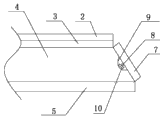
Fig. 1 is structural representation of the present invention.
Fig. 2 is the fit structure schematic diagram of light guide plate of the present invention and FPC.
Fig. 3 is the fit structure schematic diagram of diffusion sheet of the present invention and prismatic lens.
Fig. 4 is the cross-sectional schematic of dispersing lens.
Fig. 5 is the structural representation of dispersing lens.
Reference numeral is:
1---sealant tape 2---prismatic lens 3---diffusion sheet
4---light guide plate 5---reflectance coating 6---glue frames
7---FPC 8---paster LED 9---curved surfaces
10---dispersing lens 101---containing hole 102---incidence surfaces
103---curved surface.
Embodiment
Below in conjunction with Fig. 1 to Fig. 5, and embodiment is described further the present invention.
Embodiment: referring to Fig. 1 to Fig. 5.
A LCDs, comprises backlight module, and described backlight module comprises light guide plate 4, be enclosed within glue frame 6 outside light guide plate 4, be fixed on the FPC7 of glue frame 6; FPC7 is arranged at the side of light guide plate 4, and FPC7 is provided with a plurality of paster LEDs 8, and between paster LED and light guide plate, is provided with dispersing lens 10.
The present invention adopts paster LED 8 to substitute current LED lamp pearl, is conducive to reduce usage space; Next uses dispersing lens 10, and LED sends light and becomes area source through dispersing lens 10.Dispersing lens 10 can be protruding dispersing lens, also can be for pointolite being become to the symmetrical dispersing lens of rectangular shaped light source.
Further, the incidence surface 102 of described dispersing lens 10 is provided with LED containing hole 101, and incidence surface 102 is the curved surface of epirelief, and the exiting surface of dispersing lens 10 consists of two protruding curved surfaces 23; Dispersing lens 10 is symmetrical structure.
Because LED is pointolite, and rectangular shaped light source is symmetrical light sources, so dispersing lens 10 is symmetrical structure.In design process, should be by the intermediate light powerization of pointolite, thereby adopted exiting surface, be both sides projections, middle recessed structure.
Further, the side of described light guide plate 4 is set to inclined-plane, the side laminating of FPC7 and light guide plate 4, and the back side of described light guide plate 4 is provided with reflectance coating 5.
Due to light guide plate 4 when mounted, its side has one section by glue frame 6, to be covered, in order to increase further space availability ratio, the end face of the light guide plate 4 of this section is set to inclined-plane, thereby formation accommodation space, this accommodation space can be for placing FPC7, thereby saved former in placing the space of FPC7.Because the placement of FPC7 is now for tilting, may cause more light to penetrate from the back side of light guide plate 4, therefore at the back side of light guide plate 4, be provided with reflectance coating 5, most light can be gone out from the front projection of light guide plate 4.
Further, the side of described light guide plate 4 is provided with the shrinkage pool matching with paster LED 8; Paster LED 8 stretches in described shrinkage pool.
LED8 is put into shrinkage pool, be convenient to the setting of FPC7.
Further, the bottom surface of described shrinkage pool is the curved surface 9 of light diffusion.
For the light that LED8 sends can be diffused in light guide plate 4, prevent that light is concentrated, improve the light-emitting uniformity of light guide plate 4.Therefore, the bottom surface of shrinkage pool is designed to the curved surface 9 of light diffusion.
Wherein, described curved surface 9 is concave surface.Similar to the surface of recessed dispersing lens.
Further, the exiting surface of described light guide plate 4 is provided with diffusion sheet 3.
Because the light source of light guide plate 4 is to be provided by the LED8 that is arranged on its side, therefore can more or less cause, light is more in the marginal distribution of light guide plate 4, intermediate distribution is less, in order to improve further, uniformity of light, exiting surface in light guide plate 4 arranges diffusion sheet 3, and light, after diffusion sheet 3, casts out.
Further, the outer prismatic lens 2 that is also provided with of described diffusion sheet 3.
Arrange after prismatic lens 2, the light that light source is sent is assembled to display device user direction, front face brightness can be improved to approximately 100%.
Referring to Fig. 3, the exiting surface of described diffusion sheet 3 is provided with many parallel raised lines, the exiting surface of described prismatic lens 2 is also provided with many parallel raised lines, and the angle between the raised line extending direction on diffusion sheet 3 and the extending direction of the raised line on prismatic lens 2 is 75 to 90 degree.
Further, the outer sealant tape 1 that is also provided with of light guide plate 4.
Flat tape is set, the place beyond the middle part of light guide plate 4 can be blocked, prevent that foreign object from entering, damage light guide plate 4.
Below be only the application's preferred embodiment, equivalent technical solutions on this basis still falls into application protection domain.
Claims (6)
1. a LCDs, comprises backlight module, and described backlight module comprises light guide plate, be enclosed within glue frame outside light guide plate, be fixed on the FPC of glue frame; It is characterized in that: FPC is arranged at the side of light guide plate, and FPC is provided with a plurality of paster LEDs, and is provided with dispersing lens between paster LED and light guide plate.
2. a kind of LCDs according to claim 1, it is characterized in that: also comprise diffusion sheet and prismatic lens, diffusion sheet is arranged at the exiting surface of light guide plate, prismatic lens is arranged at outside diffusion sheet, the exiting surface of described diffusion sheet is provided with many parallel raised lines, the exiting surface of described prismatic lens is also provided with many parallel raised lines, and the angle between the raised line extending direction on diffusion sheet and the extending direction of the raised line on prismatic lens is 75 to 90 degree.
3. a kind of LCDs according to claim 2, is characterized in that: the side of described light guide plate is set to inclined-plane, the side laminating of FPC and light guide plate, and the back side of described light guide plate is provided with reflectance coating.
4. according to a kind of LCDs described in claim 1 or 2 or 3, it is characterized in that: the side of described light guide plate is provided with the shrinkage pool matching with paster LED; Paster LED stretches in described shrinkage pool.
5. a kind of LCDs according to claim 4, is characterized in that: the bottom surface of described shrinkage pool is the curved surface of light diffusion.
6. a kind of LCDs according to claim 1, is characterized in that: the incidence surface of described dispersing lens is provided with LED containing hole, and incidence surface is the curved surface of epirelief, and the exiting surface of dispersing lens consists of two protruding curved surfaces; Dispersing lens is symmetrical structure.
Priority Applications (1)
| Application Number | Priority Date | Filing Date | Title |
|---|---|---|---|
| CN201310748817.2A CN103645585A (en) | 2013-12-31 | 2013-12-31 | Liquid crystal display |
Applications Claiming Priority (1)
| Application Number | Priority Date | Filing Date | Title |
|---|---|---|---|
| CN201310748817.2A CN103645585A (en) | 2013-12-31 | 2013-12-31 | Liquid crystal display |
Publications (1)
| Publication Number | Publication Date |
|---|---|
| CN103645585A true CN103645585A (en) | 2014-03-19 |
Family
ID=50250827
Family Applications (1)
| Application Number | Title | Priority Date | Filing Date |
|---|---|---|---|
| CN201310748817.2A Pending CN103645585A (en) | 2013-12-31 | 2013-12-31 | Liquid crystal display |
Country Status (1)
| Country | Link |
|---|---|
| CN (1) | CN103645585A (en) |
Cited By (4)
| Publication number | Priority date | Publication date | Assignee | Title |
|---|---|---|---|---|
| CN107577069A (en) * | 2017-08-30 | 2018-01-12 | 惠科股份有限公司 | A kind of manufacture method of liquid crystal display device |
| CN107589567A (en) * | 2017-08-30 | 2018-01-16 | 惠科股份有限公司 | A kind of manufacture method of liquid crystal display device |
| CN111338129A (en) * | 2020-04-13 | 2020-06-26 | Tcl华星光电技术有限公司 | Backlight module and display device |
| CN114593382A (en) * | 2020-12-30 | 2022-06-07 | 深圳市合瑞软件有限公司 | Automobile trim board assembly and automobile |
Citations (8)
| Publication number | Priority date | Publication date | Assignee | Title |
|---|---|---|---|---|
| US20020063814A1 (en) * | 2000-11-29 | 2002-05-30 | Nec Corporation | LCD device having an improved backlight unit |
| CN1603912A (en) * | 2003-09-30 | 2005-04-06 | 鸿富锦精密工业(深圳)有限公司 | Area light source device and liquid crystal display |
| CN101158781A (en) * | 2007-11-12 | 2008-04-09 | 杨忠义 | Double face LCD |
| JP2008218039A (en) * | 2007-02-28 | 2008-09-18 | Optrex Corp | Back light unit |
| CN201401701Y (en) * | 2009-05-13 | 2010-02-10 | 厦门高卓立科技有限公司 | Backlight modular structure of liquid crystal display |
| CN102767760A (en) * | 2012-07-06 | 2012-11-07 | 广州市鸿利光电股份有限公司 | Straight-down type liquid crystal television backlight module |
| CN103217733A (en) * | 2012-01-19 | 2013-07-24 | 扬昕科技(苏州)有限公司 | Light guide plate and backlight module |
| CN203745764U (en) * | 2013-12-31 | 2014-07-30 | 东莞市亚星半导体有限公司 | Liquid crystal display |
-
2013
- 2013-12-31 CN CN201310748817.2A patent/CN103645585A/en active Pending
Patent Citations (8)
| Publication number | Priority date | Publication date | Assignee | Title |
|---|---|---|---|---|
| US20020063814A1 (en) * | 2000-11-29 | 2002-05-30 | Nec Corporation | LCD device having an improved backlight unit |
| CN1603912A (en) * | 2003-09-30 | 2005-04-06 | 鸿富锦精密工业(深圳)有限公司 | Area light source device and liquid crystal display |
| JP2008218039A (en) * | 2007-02-28 | 2008-09-18 | Optrex Corp | Back light unit |
| CN101158781A (en) * | 2007-11-12 | 2008-04-09 | 杨忠义 | Double face LCD |
| CN201401701Y (en) * | 2009-05-13 | 2010-02-10 | 厦门高卓立科技有限公司 | Backlight modular structure of liquid crystal display |
| CN103217733A (en) * | 2012-01-19 | 2013-07-24 | 扬昕科技(苏州)有限公司 | Light guide plate and backlight module |
| CN102767760A (en) * | 2012-07-06 | 2012-11-07 | 广州市鸿利光电股份有限公司 | Straight-down type liquid crystal television backlight module |
| CN203745764U (en) * | 2013-12-31 | 2014-07-30 | 东莞市亚星半导体有限公司 | Liquid crystal display |
Cited By (4)
| Publication number | Priority date | Publication date | Assignee | Title |
|---|---|---|---|---|
| CN107577069A (en) * | 2017-08-30 | 2018-01-12 | 惠科股份有限公司 | A kind of manufacture method of liquid crystal display device |
| CN107589567A (en) * | 2017-08-30 | 2018-01-16 | 惠科股份有限公司 | A kind of manufacture method of liquid crystal display device |
| CN111338129A (en) * | 2020-04-13 | 2020-06-26 | Tcl华星光电技术有限公司 | Backlight module and display device |
| CN114593382A (en) * | 2020-12-30 | 2022-06-07 | 深圳市合瑞软件有限公司 | Automobile trim board assembly and automobile |
Similar Documents
| Publication | Publication Date | Title |
|---|---|---|
| CN103529596B (en) | Backlight module and the liquid crystal indicator with this backlight module | |
| US9280009B2 (en) | Double-sided curved liquid crystal display device | |
| CN103775923B (en) | Lamp bar and the backlight module with this lamp bar | |
| US9459393B2 (en) | Backlight module structure | |
| US10132966B2 (en) | Optical element including strip-shaped prisms, light guide plate, prism, backlight module and display device | |
| CN103676321A (en) | Liquid crystal display device | |
| CN103645585A (en) | Liquid crystal display | |
| KR20140146829A (en) | Liquid crystal display apparatus | |
| CN102691945A (en) | Edge-lighting backlight module | |
| CN102635810A (en) | Backlight module | |
| US20150331174A1 (en) | Backlight unit and display device | |
| WO2017173719A1 (en) | Backlight module and display device | |
| WO2014176885A1 (en) | Direct type backlight module and liquid crystal display device | |
| US20150022756A1 (en) | Backlight module and corresponding liquid crystal display device | |
| CN109358451B (en) | Backlight module and display device thereof | |
| CN203745764U (en) | Liquid crystal display | |
| CN203240405U (en) | Backlight module | |
| US20160341878A1 (en) | Light Guide Plate and Backlight Module Having the Same | |
| CN202629831U (en) | Backlight module | |
| CN203068333U (en) | Backlight module and display device | |
| CN101625105A (en) | Light guide column and mobile communication terminal with same | |
| US20140078774A1 (en) | Backlight module suitable for transportation | |
| CN203980009U (en) | A kind of backlight module and LCDs thereof | |
| CN204268241U (en) | Backlight module, display module and display unit | |
| US9280008B2 (en) | Backlight module and liquid crystal display device using same |
Legal Events
| Date | Code | Title | Description |
|---|---|---|---|
| PB01 | Publication | ||
| PB01 | Publication | ||
| C10 | Entry into substantive examination | ||
| SE01 | Entry into force of request for substantive examination | ||
| RJ01 | Rejection of invention patent application after publication |
Application publication date: 20140319 |
|
| RJ01 | Rejection of invention patent application after publication |