KR20140146829A - Liquid crystal display apparatus - Google Patents
Liquid crystal display apparatus Download PDFInfo
- Publication number
- KR20140146829A KR20140146829A KR1020130069623A KR20130069623A KR20140146829A KR 20140146829 A KR20140146829 A KR 20140146829A KR 1020130069623 A KR1020130069623 A KR 1020130069623A KR 20130069623 A KR20130069623 A KR 20130069623A KR 20140146829 A KR20140146829 A KR 20140146829A
- Authority
- KR
- South Korea
- Prior art keywords
- liquid crystal
- light source
- crystal panel
- source unit
- diffusion member
- Prior art date
Links
Images


Classifications
-
- G—PHYSICS
- G02—OPTICS
- G02F—OPTICAL DEVICES OR ARRANGEMENTS FOR THE CONTROL OF LIGHT BY MODIFICATION OF THE OPTICAL PROPERTIES OF THE MEDIA OF THE ELEMENTS INVOLVED THEREIN; NON-LINEAR OPTICS; FREQUENCY-CHANGING OF LIGHT; OPTICAL LOGIC ELEMENTS; OPTICAL ANALOGUE/DIGITAL CONVERTERS
- G02F1/00—Devices or arrangements for the control of the intensity, colour, phase, polarisation or direction of light arriving from an independent light source, e.g. switching, gating or modulating; Non-linear optics
- G02F1/01—Devices or arrangements for the control of the intensity, colour, phase, polarisation or direction of light arriving from an independent light source, e.g. switching, gating or modulating; Non-linear optics for the control of the intensity, phase, polarisation or colour
- G02F1/13—Devices or arrangements for the control of the intensity, colour, phase, polarisation or direction of light arriving from an independent light source, e.g. switching, gating or modulating; Non-linear optics for the control of the intensity, phase, polarisation or colour based on liquid crystals, e.g. single liquid crystal display cells
- G02F1/133—Constructional arrangements; Operation of liquid crystal cells; Circuit arrangements
- G02F1/1333—Constructional arrangements; Manufacturing methods
- G02F1/133308—Support structures for LCD panels, e.g. frames or bezels
-
- G—PHYSICS
- G02—OPTICS
- G02F—OPTICAL DEVICES OR ARRANGEMENTS FOR THE CONTROL OF LIGHT BY MODIFICATION OF THE OPTICAL PROPERTIES OF THE MEDIA OF THE ELEMENTS INVOLVED THEREIN; NON-LINEAR OPTICS; FREQUENCY-CHANGING OF LIGHT; OPTICAL LOGIC ELEMENTS; OPTICAL ANALOGUE/DIGITAL CONVERTERS
- G02F1/00—Devices or arrangements for the control of the intensity, colour, phase, polarisation or direction of light arriving from an independent light source, e.g. switching, gating or modulating; Non-linear optics
- G02F1/01—Devices or arrangements for the control of the intensity, colour, phase, polarisation or direction of light arriving from an independent light source, e.g. switching, gating or modulating; Non-linear optics for the control of the intensity, phase, polarisation or colour
- G02F1/13—Devices or arrangements for the control of the intensity, colour, phase, polarisation or direction of light arriving from an independent light source, e.g. switching, gating or modulating; Non-linear optics for the control of the intensity, phase, polarisation or colour based on liquid crystals, e.g. single liquid crystal display cells
- G02F1/133—Constructional arrangements; Operation of liquid crystal cells; Circuit arrangements
- G02F1/1333—Constructional arrangements; Manufacturing methods
- G02F1/1335—Structural association of cells with optical devices, e.g. polarisers or reflectors
- G02F1/1336—Illuminating devices
- G02F1/133602—Direct backlight
- G02F1/133606—Direct backlight including a specially adapted diffusing, scattering or light controlling members
-
- G—PHYSICS
- G02—OPTICS
- G02F—OPTICAL DEVICES OR ARRANGEMENTS FOR THE CONTROL OF LIGHT BY MODIFICATION OF THE OPTICAL PROPERTIES OF THE MEDIA OF THE ELEMENTS INVOLVED THEREIN; NON-LINEAR OPTICS; FREQUENCY-CHANGING OF LIGHT; OPTICAL LOGIC ELEMENTS; OPTICAL ANALOGUE/DIGITAL CONVERTERS
- G02F1/00—Devices or arrangements for the control of the intensity, colour, phase, polarisation or direction of light arriving from an independent light source, e.g. switching, gating or modulating; Non-linear optics
- G02F1/01—Devices or arrangements for the control of the intensity, colour, phase, polarisation or direction of light arriving from an independent light source, e.g. switching, gating or modulating; Non-linear optics for the control of the intensity, phase, polarisation or colour
- G02F1/13—Devices or arrangements for the control of the intensity, colour, phase, polarisation or direction of light arriving from an independent light source, e.g. switching, gating or modulating; Non-linear optics for the control of the intensity, phase, polarisation or colour based on liquid crystals, e.g. single liquid crystal display cells
- G02F1/133—Constructional arrangements; Operation of liquid crystal cells; Circuit arrangements
- G02F1/1333—Constructional arrangements; Manufacturing methods
- G02F1/1335—Structural association of cells with optical devices, e.g. polarisers or reflectors
-
- G—PHYSICS
- G02—OPTICS
- G02F—OPTICAL DEVICES OR ARRANGEMENTS FOR THE CONTROL OF LIGHT BY MODIFICATION OF THE OPTICAL PROPERTIES OF THE MEDIA OF THE ELEMENTS INVOLVED THEREIN; NON-LINEAR OPTICS; FREQUENCY-CHANGING OF LIGHT; OPTICAL LOGIC ELEMENTS; OPTICAL ANALOGUE/DIGITAL CONVERTERS
- G02F1/00—Devices or arrangements for the control of the intensity, colour, phase, polarisation or direction of light arriving from an independent light source, e.g. switching, gating or modulating; Non-linear optics
- G02F1/01—Devices or arrangements for the control of the intensity, colour, phase, polarisation or direction of light arriving from an independent light source, e.g. switching, gating or modulating; Non-linear optics for the control of the intensity, phase, polarisation or colour
- G02F1/13—Devices or arrangements for the control of the intensity, colour, phase, polarisation or direction of light arriving from an independent light source, e.g. switching, gating or modulating; Non-linear optics for the control of the intensity, phase, polarisation or colour based on liquid crystals, e.g. single liquid crystal display cells
- G02F1/133—Constructional arrangements; Operation of liquid crystal cells; Circuit arrangements
- G02F1/1333—Constructional arrangements; Manufacturing methods
- G02F1/133308—Support structures for LCD panels, e.g. frames or bezels
- G02F1/133314—Back frames
-
- G—PHYSICS
- G02—OPTICS
- G02F—OPTICAL DEVICES OR ARRANGEMENTS FOR THE CONTROL OF LIGHT BY MODIFICATION OF THE OPTICAL PROPERTIES OF THE MEDIA OF THE ELEMENTS INVOLVED THEREIN; NON-LINEAR OPTICS; FREQUENCY-CHANGING OF LIGHT; OPTICAL LOGIC ELEMENTS; OPTICAL ANALOGUE/DIGITAL CONVERTERS
- G02F1/00—Devices or arrangements for the control of the intensity, colour, phase, polarisation or direction of light arriving from an independent light source, e.g. switching, gating or modulating; Non-linear optics
- G02F1/01—Devices or arrangements for the control of the intensity, colour, phase, polarisation or direction of light arriving from an independent light source, e.g. switching, gating or modulating; Non-linear optics for the control of the intensity, phase, polarisation or colour
- G02F1/13—Devices or arrangements for the control of the intensity, colour, phase, polarisation or direction of light arriving from an independent light source, e.g. switching, gating or modulating; Non-linear optics for the control of the intensity, phase, polarisation or colour based on liquid crystals, e.g. single liquid crystal display cells
- G02F1/133—Constructional arrangements; Operation of liquid crystal cells; Circuit arrangements
- G02F1/1333—Constructional arrangements; Manufacturing methods
- G02F1/133308—Support structures for LCD panels, e.g. frames or bezels
- G02F1/13332—Front frames
Landscapes
- Physics & Mathematics (AREA)
- Nonlinear Science (AREA)
- Mathematical Physics (AREA)
- Chemical & Material Sciences (AREA)
- Crystallography & Structural Chemistry (AREA)
- General Physics & Mathematics (AREA)
- Optics & Photonics (AREA)
- Liquid Crystal (AREA)
- Planar Illumination Modules (AREA)
Abstract
Description
본 발명은 액정 디스플레이 장치에 관한 것으로, 보다 구체적으로 직하 타입의 액정 디스플레이 장치에 관한 것이다.The present invention relates to a liquid crystal display device, and more particularly to a direct-type liquid crystal display device.
평판 디스플레이 장치(Flat Panel Display Apparatus)는 두께가 얇고 가벼운 영상 표시 장치로서, 최근 들어서는 평판 디스플레이로서 액정 디스플레이 장치(Liquid Crystal Display Aparatatus)가 시장의 주류를 이루고 있다.2. Description of the Related Art A flat panel display apparatus is a thin and lightweight image display apparatus. In recent years, a liquid crystal display apparatus (Liquid Crystal Display Apparatatus) as a flat panel display has become mainstream in the market.
액정 디스플레이 장치는 광원유닛의 배치 형태에 따라 엣지(Edge) 타입과 직하(Direct) 타입으로 나누어진다. 엣지 타입은 광원유닛이 액정패널 측면에 배치되며, 직하 타입은 광원유닛이 액정패널 후방에 배치된다. 직하 타입은 액정패널 후방에 LED와 같은 광원 패키지들이 균일하게 퍼져 있기 때문에 엣지 타입보다 화면밝기의 균일성 유지가 용이한 이점이 있다. 이에 따라, 액정 디스플레이 장치는 직하 타입으로 설계되는 추세가 증가하고 있고, 슬림화 트렌드에 따라 두께도 점차 슬림화되고 있는 추세이다.The liquid crystal display device is divided into an edge type and a direct type depending on the arrangement of the light source units. In the edge type, the light source unit is arranged on the side of the liquid crystal panel, and in the direct lower type, the light source unit is arranged on the rear side of the liquid crystal panel. In the direct type, since the light source packages such as the LED are uniformly spread on the back of the liquid crystal panel, there is an advantage that the uniformity of the screen brightness can be maintained more easily than the edge type. Accordingly, the liquid crystal display device has been increasingly designed to be a direct-type type, and the thickness thereof is gradually becoming thinner according to the slimming trend.
직하 타입의 액정 디스플레이 장치는 두께가 슬림해지는 경우, 액정패널과 광원유닛 사이의 거리가 가까워진다. 액정패널과 광원유닛 사이의 거리는 일반적으로 광학거리라고 지칭한다. 이러한 광학거리가 짧아지는 경우, 액정 디스플레이 장치는 광학거리가 긴 경우보다 빛을 확산시키는 양이 더 많아야 한다.When the direct-down type liquid crystal display device becomes slim, the distance between the liquid crystal panel and the light source unit becomes close to each other. The distance between the liquid crystal panel and the light source unit is generally referred to as an optical distance. When such an optical distance is shortened, the liquid crystal display device should have a larger amount of diffusing light than when the optical distance is long.
종래의 직하 타입의 액정 디스플레이 장치는 슬림화 설계로 광학거리가 짧아지는 경우, 기존의 확산판 및 광학시트의 배치로는 빛을 충분히 확산시킬 수 없어, 광원 패키지들 사이 구간을 마주보는 액정패널의 구간에 암부가 발생하여 액정 디스플레이 장치의 화질이 저하되는 문제가 있다.When the optical distance is shortened due to the slim design of the conventional direct type liquid crystal display device, it is impossible to sufficiently diffuse the light by the arrangement of the conventional diffuser plate and the optical sheet so that the interval of the liquid crystal panel facing the section between the light source packages There is a problem that the image quality of the liquid crystal display device is deteriorated.
따라서, 본 발명의 목적은 직하 타입에서 슬림화를 구현하면서 화질 저하를 발생시키지 않는 액정 디스플레이 장치를 제공하는 것에 있다.SUMMARY OF THE INVENTION It is therefore an object of the present invention to provide a liquid crystal display device which realizes slimming in a direct-down type and does not cause image quality deterioration.
상기 목적을 달성하기 위해 본 발명의 일 실시예에 따른 액정 디스플레이 장치로서, 영상을 표시하는 액정패널, 상기 액정패널의 후방에 배치되며 상기 액정패널 방향으로 빛을 공급하는 광원유닛 및 상기 액정패널과 상기 광원유닛 사이에 배치되며, 상기 광원유닛으로부터 나오는 빛을 확산시키기 위한 복수의 기공이 형성된 확산부재를 포함하는 것을 특징으로 하는 액정 디스플레이 장치를 제공한다.According to an aspect of the present invention, there is provided a liquid crystal display device comprising: a liquid crystal panel for displaying an image; a light source unit disposed behind the liquid crystal panel and supplying light toward the liquid crystal panel; And a diffusion member disposed between the light source units and having a plurality of pores for diffusing light emitted from the light source unit.
상기 확산부재는 상기 광원유닛을 둘러쌀 수 있다.The diffusion member may surround the light source unit.
상기 액정 디스플레이 장치는 상기 액정패널과 상기 확산부재 사이에 배치되는 적어도 하나의 광학시트 및 상기 액정패널, 상기 광원유닛, 상기 확산부재 및 상기 광학시트를 수용하는 패키징 유닛을 더 포함하며, 상기 확산부재는 상기 패키징 유닛 내에서 상기 광원유닛과 상기 광학시트 사이의 공간에 채워질 수 있다.The liquid crystal display device further comprises at least one optical sheet disposed between the liquid crystal panel and the diffusion member and a packaging unit for accommodating the liquid crystal panel, the light source unit, the diffusion member, and the optical sheet, Can be filled in the space between the light source unit and the optical sheet in the packaging unit.
상기 패키징 유닛은, 상기 액정패널에서 나오는 영상을 외부로 내보내기 위한 개구가 형성된 전면 샤시 및 상기 전면 샤시와 결합되어 상기 액정패널, 상기 광원유닛, 상기 확산부재 및 상기 광학시트를 수용하는 공간을 형성하는 후면 샤시를 포함하며, 상기 광원유닛은 상기 후면 샤시의 내측면에 장착될 수 있다.The packaging unit includes a front chassis having an opening for emitting an image from the liquid crystal panel to the outside, and a space coupled to the front chassis to accommodate the liquid crystal panel, the light source unit, the diffusion member, and the optical sheet And a rear chassis, wherein the light source unit can be mounted on an inner surface of the rear chassis.
상기 확산부재에는 상기 광원유닛을 둘러싸는 적어도 하나의 오목부가 형성될 수 있다.The diffusion member may be provided with at least one concave portion surrounding the light source unit.
상기 오목부는 상기 광원유닛과 소정 거리 이격될 수 있다.The concave portion may be spaced apart from the light source unit by a predetermined distance.
상기 오목부의 단면 형상은 반원 형상, 삼각 형상 및 사각 형상 중 어느 하나일 수 있다.The cross-sectional shape of the concave portion may be any one of semicircular, triangular, and quadrangular shapes.
상기 광원유닛은, 상기 후면 샤시의 내측면에 장착되는 인쇄회로기판 및 서로 소정 거리 이격되며 상기 인쇄회로기판에 장착되는 복수의 광원 패키지들을 포함하며, 상기 오목부는 상기 복수의 광원 패키지들의 개수에 대응되게 복수 개가 형성될 수 있다.The light source unit includes a printed circuit board mounted on an inner surface of the rear chassis, and a plurality of light source packages spaced apart from each other by a predetermined distance and mounted on the printed circuit board, wherein the recesses correspond to the number of the plurality of light source packages Pluralities can be formed.
상기 확산부재는 상기 광원유닛과 소정 거리 이격되어 배치될 수 있다.The diffusion member may be spaced apart from the light source unit by a predetermined distance.
상기 확산부재는 상기 액정패널에 평행하게 배열될 수 있다.The diffusion member may be arranged parallel to the liquid crystal panel.
상기 액정 디스플레이 장치는 상기 광학시트와 상기 확산부재 사이에 배치되는 확산판을 더 포함할 수 있다.The liquid crystal display device may further include a diffusion plate disposed between the optical sheet and the diffusion member.
상기 확산부재는 스티로폼 또는 스펀지일 수 있다.The diffusion member may be a styrofoam or a sponge.
이상과 같은 다양한 실시예들에 따라, 슬림화를 구현하면서 화질 저하가 발생되지 않는 직하 타입의 액정 디스플레이 장치를 제공할 수 있다.According to various embodiments as described above, it is possible to provide a direct-type liquid crystal display device in which image quality is not deteriorated while realizing slimming.
도 1은 본 발명의 일 실시예에 따른 액정 디스플레이 장치의 분해 사시도이다.
도 2는 도 1의 액정 디스플레이 장치의 액정패널 조립체의 단면도이다.
도 3은 도 2의 액정패널 조립체의 좌측 단부 영역을 확대한 단면도이다.
도 4는 도 2의 액정패널 조립체의 광원유닛의 평면도이다.
도 5는 도 4의 I - I 선에 따른 단면도이다.
도 6은 도 2의 액정패널 조립체의 확산부재의 사시도이다.
도 7은 도 6의 확산부재의 단면도이다.
도 8 및 도 9는 본 발명의 다른 실시예에 따른 확산부재를 나타내는 도면이다.
도 10은 도 2의 액정패널 조립체의 광원유닛에서 나온 빛이 확산부재를 통해 확산되는 모습을 나타내는 도면이다.
도 11은 본 발명의 다른 실시예에 따른 액정패널 조립체의 단면도이다.
도 12는 도 11의 액정패널 조립체의 좌측 단부 영역을 확대한 단면도이다.
도 13은 본 발명의 또 다른 실시예에 따른 액정패널 조립체의 단면도이다.
도 14는 도 13의 액정패널 조립체의 좌측 단부 영역을 확대한 단면도이다.1 is an exploded perspective view of a liquid crystal display device according to an embodiment of the present invention.
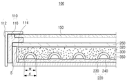
2 is a sectional view of a liquid crystal panel assembly of the liquid crystal display device of FIG.
3 is an enlarged cross-sectional view of the left end region of the liquid crystal panel assembly of FIG.
4 is a plan view of the light source unit of the liquid crystal panel assembly of Fig.
5 is a sectional view taken along the line I - I in Fig.
Figure 6 is a perspective view of a diffusion member of the liquid crystal panel assembly of Figure 2;
7 is a cross-sectional view of the diffusion member of Fig.
8 and 9 are views showing a diffusion member according to another embodiment of the present invention.
10 is a view showing a state where light emitted from a light source unit of the liquid crystal panel assembly of FIG. 2 is diffused through a diffusion member.
11 is a cross-sectional view of a liquid crystal panel assembly according to another embodiment of the present invention.
12 is an enlarged cross-sectional view of the left end region of the liquid crystal panel assembly of Fig.
13 is a cross-sectional view of a liquid crystal panel assembly according to another embodiment of the present invention.
14 is an enlarged cross-sectional view of the left end region of the liquid crystal panel assembly of Fig.
이하, 첨부된 도면을 참조하여 본 발명의 실시예 들에 대하여 상세하게 설명한다. 이하에서 설명되는 실시예들은 발명의 이해를 돕기 위하여 예시적으로 나타낸 것이며, 본 발명은 여기서 설명되는 실시예와 다르게 다양하게 변형되어 실시될 수 있음이 이해되어야 할 것이다. 다만, 본 발명을 설명함에 있어서 관련된 공지 기능 혹은 구성요소에 대한 구체적인 설명이 본 발명의 요지를 불필요하게 흐릴 수 있다고 판단되는 경우 그 상세한 설명 및 구체적인 도시를 생략한다. 또한, 첨부된 도면은 발명의 이해를 돕기 위하여 실제 축척대로 도시된 것이 아니라 일부 구성요소의 치수가 과장되게 도시될 수 있다.Hereinafter, embodiments of the present invention will be described in detail with reference to the accompanying drawings. It is to be understood that the embodiments described below are provided for illustrative purposes only, and that the present invention may be embodied with various modifications and alterations. In the following description, well-known functions or constructions are not described in detail to avoid obscuring the subject matter of the present invention. In addition, the attached drawings are not drawn to scale in order to facilitate understanding of the invention, but the dimensions of some of the components may be exaggerated.
도 1은 본 발명의 일 실시예에 따른 액정 디스플레이 장치의 분해 사시도이며, 도 2는 도 1의 액정 디스플레이 장치의 액정패널 조립체의 단면도이며, 도 3은 도 2의 액정패널 조립체의 좌측 단부 영역을 확대한 단면도이다.2 is a cross-sectional view of the liquid crystal panel assembly of the liquid crystal display device of FIG. 1, and FIG. 3 is a cross-sectional view of the liquid crystal panel assembly of FIG. Fig.
도 1을 참조하면, 액정 디스플레이 장치(1)는 하우징(10) 및 액정패널 조립체(100)를 포함한다.Referring to FIG. 1, a liquid
하우징(10)은 액정패널 조립체(100), 액정패널 조립체(100)의 동작을 제어하는 제어 보드(미도시) 및 액정패널 조립체(100)에 전력을 공급하는 파워 보드(미도시) 등의 액정 디스플레이 장치(1)의 각종 부품들을 수용한다.The
이러한 하우징(10)은 상호 착탈 가능하게 결합되는 전면 하우징(12)과 후면 하우징(14)을 포함한다. 전면 하우징(12)은 액정 디스플레이 장치(1)의 전면 테두리를 형성하며, 전면 하우징(12)에는 영상이 외부로 노출될 수 있게 직사각형의 전방 개구(12a)가 형성된다. 후면 하우징(14)은 내측면에 수용공간이 마련되어 전술한 각종 부품들을 수용한다.The
도 2 및 도 3을 참조하면, 액정패널 조립체(100)는 패키징 유닛(110), 액정패널(150) 및 백라이트 유닛(200)을 포함한다.2 and 3, a liquid
패키징 유닛(110)은 액정패널(150) 및 백라이트 유닛(200)을 하나의 모듈로 패키징하는 것으로, 전면 샤시(112), 후면 샤시(114) 및 중간 샤시(116)를 포함한다.The
전면 샤시(112)와 후면 샤시(114)는 중간 샤시(116)를 매개로 하여 서로 결합됨으로써, 액정패널 조립체(100)의 각종 부품들을 수용하는 공간을 형성한다. 그리고, 전면 샤시(112)에는 액정패널(120)에서 나오는 영상을 외부로 내보내기 위한 개구(112a)가 형성된다.The
중간 샤시(116)는 전면 샤시(112) 및 후면 샤시(114)와 더불어 액정패널 조립체(100)의 일부 부품들을 지지한다. 이를 위해, 중간 샤시(116)는 액정패널 조립체(100) 안에서 가장자리 영역에 배치되며 전면 샤시(112)와 하부 샤시(114) 사이에 배치된다.The
액정패널(150)은 백라이트 유닛(200)이 제공한 빛을 이용하여 컬러 영상을 표시한다. 액정패널(150)은 컬러 필터층을 가진 컬러 필터 기판(미도시)과 박막 트랜지스터를 가진 박막 트랜지스터 기판(미도시)을 포함하며, 컬러 필터 기판과 박막 트랜지스터 기판 사이에는 액정(미도시)이 수용된다. 액정패널(150)은 이미 공지된 구성이므로, 보다 자세한 설명은 생략한다.The
백라이트 유닛(200)은 액정패널(150)로 빛을 공급하는 것으로, 이러한 백라이트 유닛(200)은 광원유닛(220), 광학시트(260) 및 확산부재(300)를 포함한다.The
광원유닛(220)은 액정패널(150)의 후방에서 액정패널(150)과 평행하게 배열된다. 즉, 본 실시예에서의 광원유닛(540)은 직하(Direct)형으로 구비된다. 광원유닛(220)에 대해서는 하기 도 4 및 도 5를 참조하여 자세히 설명한다.The
도 4는 도 2의 액정패널 조립체의 광원유닛의 평면도이며, 도 5는 도 4의 I - I 선에 따른 단면도이다.Fig. 4 is a plan view of the light source unit of the liquid crystal panel assembly of Fig. 2, and Fig. 5 is a sectional view taken along the line I-I of Fig.
도 4를 참조하면, 광원유닛(220)은 복수 개가 구비되며, 각각의 광원유닛(220A 내지 220B)는 후면 샤시(114)의 바닥면(114a)에 장착된다. 각각의 광원유닛(220)은 서로 소정 거리를 두고 평행하게 배열된다. 이러한 광원유닛(220)은 사각 플레이트 형상의 인쇄회로보드(230) 및 인쇄회로보드(230) 상에 장착되어 광을 발생시키는 복수의 광원 패키지들(240)을 포함한다.Referring to FIG. 4, a plurality of
인쇄회로보드(230)는 그 상면에 실장된 복수의 광원 패키지들(240)을 지지하며 그 광원 패키지들(240)에게 전력원(power source, 미도시)으로부터 공급되는 전력을 전달한다.The printed
광원 패키지들(240)은 액정패널(150)을 향해 빛을 제공한다. 각각의 광원 패키지(240)의 구조에 대하여 도 5를 참조하여 설명하면 다음과 같다.The light source packages 240 provide light toward the
도 5를 참조하면, 광원 패키지(240)는 땜납(241)을 사용하여 전술한 인쇄회로보드(230)에 장착되며, 발광 다이오드(242), 형광체(243), 한 쌍의 전극(244, 245), 및 프레임(246)을 포함한다.5, the
발광 다이오드(242)는 잘 알려진 바와 같이 빛을 생성하는 소자이다. 형광체(243)는 발광 다이오드(242)에 의해 생성된 특정 색상의 빛을 광원유닛(220)의 용도에 적합한 다른 색상(예로써, 화이트 칼라)으로 변환한다. 또한 형광체(243)는 볼록 렌즈 형태의 외표면(243a)을 통해 빛을 널리 확산시키는 역할을 한다. 대안적으로, 광원 패키지(240)를 커버하도록 배치된 광학 렌즈(미도시)가 형광체(243)의 빛 확산 기능을 대신할 수도 있다. 한 쌍의 전극(244, 245)은 발광 다이오드(242)와 인쇄회로보드(230)를 전기적으로 연결하기 위한 부품이고, 프레임(246)은 전술한 발광 다이오드(242), 형광체(243), 및 한 쌍의 전극(244, 245)을 패키징하기 위한 부품이다.The
다시, 도 2 및 도 3을 참조하면, 광학시트(260)는 액정패널(150)과 확산부재(300) 사이에 배치되며, 하부 샤시(114)와 중간 샤시(116)에 의해 고정된다. 광학시트(160)는 확산 시트, 프리즘 시트 등으로 복수 개가 구비될 수 있으며, 확산부재(300)로부터 나온 빛을 확산시키고 휘도를 개선한다.2 and 3, the
확산부재(300)는 광원유닛(220)으로부터 나오는 빛을 확산시키기 위한 것으로, 액정패널(150)과 광원유닛(220) 사이, 구체적으로, 광원유닛(220)과 광학시트(260) 사이에 배치된다. 여기서, 확산부재(300)는 후면 샤시(114) 내에서 광원유닛(220)과 광학시트(260) 사이의 공간(S)에 채워지며 광원유닛(220)을 둘러싸는 형태로 형성된다.The
확산부재(300)에는 광원유닛(220)으로부터 나온 빛을 확산시키기 위한 복수의 기공들(320)이 형성된다. 복수의 기공들(320)은 확산부재(300) 내에서 전체적으로 분산되어 골고루 형성된다. 광원유닛(220)으로부터 나온 빛은 확산부재(300)를 통과할 때 복수의 기공들(320)을 통과하면서 골고루 확산될 수 있다.The
이러한 확산부재(300)는 복수의 기공들(320)이 형성된 일반적인 스티로폼 또는 스펀지로 구비될 수 있다. 확산부재(300)는 복수의 기공들(320)이 형성되어 있다면 기타 다른 재질로 이루어지는 것도 가능하다.The
이하, 하기 도 6 내지 도 9를 참조하여 확산부재(300)에 대해 더 자세히 설명한다.Hereinafter, the
도 6은 도 2의 액정패널 조립체의 확산부재의 사시도이며, 도 7은 도 6의 확산부재의 단면도이며, 도 8 및 도 9는 본 발명의 다른 실시예에 따른 확산부재를 나타내는 도면이다.FIG. 6 is a perspective view of a diffusion member of the liquid crystal panel assembly of FIG. 2, FIG. 7 is a cross-sectional view of the diffusion member of FIG. 6, and FIGS. 8 and 9 are views showing a diffusion member according to another embodiment of the present invention.
도 6 및 도 7을 참조하면, 확산부재(300)의 저면(302)에는 복수의 오목부들(350)이 형성된다. 복수의 오목부들(350)은 복수의 광원유닛(220, 도 4 참조)의 광원 패키지들(240, 도 4 참조)에 대응되게 형성된다.Referring to FIGS. 6 and 7, a plurality of
복수의 오목부들(350)들의 단면 형상은 광원 패키지(240)의 단면 형상에 대응되게 반원 형상으로 형성된다. 이에 한정되는 것은 아니며, 도 8과 같이 복수의 오목부들(360)의 단면 형상은 삼각형 형상으로 형성되거나 또는 도 9와 같이 복수의 오목부들(370)의 단면 형상은 사각형 형상으로도 형성될 수 있다. 복수의 오목부들의 단면 형상은 광원 패키지들(240)을 둘러쌀 수 있는 형상이라면 이외의 기타 다른 형상으로 형성될 수도 있다.The cross-sectional shapes of the plurality of
다시 도 3을 참조하면, 오목부(350)의 지름(d)은 광원 패키지(240)를 둘러쌀 수 있도록 광원 패키지(240의 폭(w)보다 크게 형성된다. 오목부(350)는 광원 패키지(240)로부터의 빛의 방출이 원활할 수 있도록 광원 패키지(240)와 소정 거리 이격된다.3, the diameter d of the
이하에서는, 광원유닛(220)에서 나온 빛이 확산부재(300)를 통해 확산되는 모습을 보다 자세히 설명한다.Hereinafter, how light emitted from the
도 10은 도 2의 액정패널 조립체의 광원유닛에서 나온 빛이 확산부재를 통해 확산되는 모습을 나타내는 도면이다.10 is a view showing a state where light emitted from a light source unit of the liquid crystal panel assembly of FIG. 2 is diffused through a diffusion member.
도 10을 참조하면, 광원유닛(220)으로부터 나온 빛은 확산부재(300)를 통과한다. 빛은 확산부재(300)의 복수의 기공들(320)를 통과하면서 고르게 확산될 수 있다.Referring to FIG. 10, light emitted from the
확산부재(300)는 앞서 살펴 본 바와 같이 각각의 광원 패키지(240)를 둘러싸면서 후면 샤시(114) 내에서 광원유닛(220)과 광학시트(260) 사이의 공간(S)을 채워질 수 있도록 배치되므로, 각각의 광원 패키지(220)에서 나온 빛이 광학시트(260)까지 도달할때까지 지속적으로 빛을 고르게 확산시킬 수 있다. 이에 따라, 본 실시예에서는 각각의 광원 패키지(220) 사이에서의 빛의 확산(A)도 원활히 이루어질 수 있다.The
본 실시예에서는 각각의 광원 패키지(220) 사이 공간에서도 빛의 확산이 고르게 이루어지므로, 각각의 광원 패키지(220) 사이 공간을 마주하는 액정패널(150)의 구간에 암부가 발생되지 않는다. 따라서, 본 실시예에 따른 액정 디스플레이 장치(1, 도 1 참조)는 두께를 슬림화하는 경우에도 암부로 인한 화질 저하가 발생되지 않는다.In this embodiment, since the light is uniformly diffused even in the spaces between the light source packages 220, the dark portions are not generated in the section of the
아울러, 본 실시예에 따른 액정 디스플레이 장치(1)는 복수의 기공들(320)이 형성된 확산부재(300)를 값이 싼 일반적인 스티로폼 또는 스펀지로 제조할 수 있으므로, 비용을 절감하고 제조효율을 높일 수 있다.In addition, the liquid
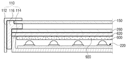
도 11은 본 발명의 다른 실시예에 따른 액정패널 조립체의 단면도이며, 도 12는 도 11의 액정패널 조립체의 좌측 단부 영역을 확대한 단면도이다.FIG. 11 is a cross-sectional view of a liquid crystal panel assembly according to another embodiment of the present invention, and FIG. 12 is an enlarged cross-sectional view of a left end region of the liquid crystal panel assembly of FIG.
도 11 및 도 12를 참조하면, 액정패널 조립체(500)는 패키징 유닛(110), 액정패널(150) 및 백라이트 유닛(600)을 포함한다.11 and 12, a liquid
패키징 유닛(110) 및 액정패널(150)은 앞선 실시예에서와 형상 및 기능이 실질적으로 동일하므로 동일한 참조번호를 사용하며 이에 대한 설명을 생략한다.Since the
백라이트 유닛(600)은 광원유닛(220), 광학시트(260), 확산부재(300) 및 확산판(620)을 포함한다.The
광원유닛(220), 광학시트(260) 및 확산부재(300)는 앞선 실시예에서와 형상 및 기능이 실질적으로 동일하므로 동일한 참조번호를 사용하며 이에 대한 설명을 생략한다.The
확산판(620)은 광학시트(260)와 확산부재(300) 사이에 배치된다. 확산판(620)은 확산부재(330)를 통과한 빛을 다시 균일하게 확산시킨다.The
본 실시예에서는 확산부재(300)와 더불어 확산판(620)이 더 구비되므로 광원유닛(220)에서 나온 빛의 확산 효율이 더욱 증대될 수 있다.The diffusing efficiency of light emitted from the
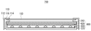
도 13은 본 발명의 또 다른 실시예에 따른 액정패널 조립체의 단면도이며, 도 14는 도 13의 액정패널 조립체의 좌측 단부 영역을 확대한 단면도이다.FIG. 13 is a cross-sectional view of a liquid crystal panel assembly according to another embodiment of the present invention, and FIG. 14 is an enlarged cross-sectional view of a left end region of the liquid crystal panel assembly of FIG.
도 13 및 도 14를 참조하면, 액정패널 조립체(700)는 패키징 유닛(110), 액정패널(150) 및 백라이트 유닛(800)을 포함한다.13 and 14, a liquid
패키징 유닛(110) 및 액정패널(150)은 앞선 실시예에서와 형상 및 기능이 실질적으로 동일하므로 동일한 참조번호를 사용하며 이에 대한 설명을 생략한다.Since the
백라이트 유닛(800)은 광원유닛(220), 광학시트(260), 확산판(620) 및 확산부재(900)를 포함한다.The
광원유닛(220), 광학시트(260) 및 확산판(620)은 앞선 실시예에서와 형상 및 기능이 실질적으로 동일하므로 동일한 참조번호를 사용하며 이에 대한 설명을 생략한다.The
확산부재(900)는 광원유닛(260)과 소정 거리 이격되어 배치되며, 액정패널(150)에 평행하게 배열된다. 확산부재(900)는 육면체 형상으로 형성되며 복수의 기공들(920)을 포함한다. 확산부재(900)는 앞선 실시예에서와 같이 스티로폼 또는 스펀지로 구비될 수 있다.The
본 실시예에서의 확산부재(900)는 앞선 실시예에서의 확산부재(300)와 달리 복수의 오목부가 형성되지 않으므로, 확산부재(900)의 제조가 더욱 간편해져 제조비용 및 제조시간을 더욱 절감할 수 있다.Since the
이상과 같이, 본 발명은 비록 한정된 실시예와 도면에 의해 설명되었으나, 본 발명은 이것에 의해 한정되지 않으며, 본 발명이 속하는 기술 분야에서 통상의 지식을 가진 자에 의해 본 발명의 기술 사상과 아래에 기재될 특허청구범위의 균등범위 내에서 다양한 수정 및 변형 가능함은 물론이다.While the present invention has been particularly shown and described with reference to exemplary embodiments thereof, it is to be understood that the invention is not limited to the disclosed exemplary embodiments. It will be understood by those skilled in the art that various changes in form and details may be made therein without departing from the spirit and scope of the invention.
1: 액정 디스플레이 장치 10: 하우징
100: 액정패널 조립체 110: 패키징 유닛
150: 액정패널 200: 백라이트 유닛
220: 광원유닛 260: 광학시트
300: 확산부재1: liquid crystal display device 10: housing
100: liquid crystal panel assembly 110: packaging unit
150: liquid crystal panel 200: backlight unit
220: light source unit 260: optical sheet
300: diffusion member
Claims (12)
상기 액정패널의 후방에 배치되며 상기 액정패널 방향으로 빛을 공급하는 광원유닛; 및
상기 액정패널과 상기 광원유닛 사이에 배치되며, 상기 광원유닛으로부터 나오는 빛을 확산시키기 위한 복수의 기공이 형성된 확산부재;를 포함하는 것을 특징으로 하는 액정 디스플레이 장치.A liquid crystal panel for displaying an image;
A light source unit disposed behind the liquid crystal panel and supplying light toward the liquid crystal panel; And
And a diffusion member disposed between the liquid crystal panel and the light source unit and having a plurality of pores for diffusing light emitted from the light source unit.
상기 확산부재는 상기 광원유닛을 둘러싸는 것을 특징으로 하는 액정 디스플레이 장치.The method according to claim 1,
And the diffusion member surrounds the light source unit.
상기 액정패널과 상기 확산부재 사이에 배치되는 적어도 하나의 광학시트; 및
상기 액정패널, 상기 광원유닛, 상기 확산부재 및 상기 광학시트를 수용하는 패키징 유닛;을 더 포함하며,
상기 확산부재는 상기 패키징 유닛 내에서 상기 광원유닛과 상기 광학시트 사이의 공간에 채워지는 것을 특징으로 하는 액정 디스플레이 장치.3. The method of claim 2,
At least one optical sheet disposed between the liquid crystal panel and the diffusion member; And
And a packaging unit for accommodating the liquid crystal panel, the light source unit, the diffusion member, and the optical sheet,
Wherein the diffusion member is filled in a space between the light source unit and the optical sheet in the packaging unit.
상기 패키징 유닛은,
상기 액정패널에서 나오는 영상을 외부로 내보내기 위한 개구가 형성된 전면 샤시; 및
상기 전면 샤시와 결합되어 상기 액정패널, 상기 광원유닛, 상기 확산부재 및 상기 광학시트를 수용하는 공간을 형성하는 후면 샤시;를 포함하며,
상기 광원유닛은 상기 후면 샤시의 내측면에 장착되는 것을 특징으로 하는 액정 디스플레이 장치.3. The method of claim 2,
The packaging unit includes:
A front chassis having an opening for emitting an image from the liquid crystal panel to the outside; And
And a rear chassis coupled to the front chassis to form a space for accommodating the liquid crystal panel, the light source unit, the diffusion member, and the optical sheet,
And the light source unit is mounted on the inner surface of the rear chassis.
상기 확산부재에는 상기 광원유닛을 둘러싸는 적어도 하나의 오목부가 형성되는 것을 특징으로 하는 액정 디스플레이 장치.5. The method of claim 4,
And at least one concave portion surrounding the light source unit is formed in the diffusion member.
상기 오목부는 상기 광원유닛과 소정 거리 이격되는 것을 특징으로 하는 액정 디스플레이 장치.6. The method of claim 5,
Wherein the concave portion is spaced apart from the light source unit by a predetermined distance.
상기 오목부의 단면 형상은 반원 형상, 삼각 형상 및 사각 형상 중 어느 하나인 것을 특징으로 하는 액정 디스플레이 장치.6. The method of claim 5,
Wherein the cross-sectional shape of the concave portion is one of a semicircular shape, a triangular shape, and a quadrangular shape.
상기 광원유닛은,
상기 후면 샤시의 내측면에 장착되는 인쇄회로기판; 및
서로 소정 거리 이격되며 상기 인쇄회로기판에 장착되는 복수의 광원 패키지들;을 포함하며,
상기 오목부는 상기 복수의 광원 패키지들의 개수에 대응되게 복수 개가 형성되는 것을 특징으로 하는 액정 디스플레이 장치.6. The method of claim 5,
The light source unit includes:
A printed circuit board mounted on an inner surface of the rear chassis; And
A plurality of light source packages spaced apart from each other by a predetermined distance and mounted on the printed circuit board,
Wherein a plurality of the recesses are formed corresponding to the number of the plurality of light source packages.
상기 확산부재는 상기 광원유닛과 소정 거리 이격되어 배치되는 것을 특징으로 하는 액정 디스플레이 장치.The method according to claim 1,
And the diffusion member is spaced apart from the light source unit by a predetermined distance.
상기 확산부재는 상기 액정패널에 평행하게 배열되는 것을 특징으로 하는 액정 디스플레이 장치.10. The method of claim 9,
And the diffusion member is arranged parallel to the liquid crystal panel.
상기 광학시트와 상기 확산부재 사이에 배치되는 확산판을 더 포함하는 것을 특징으로 하는 액정 디스플레이 장치.The method according to claim 1,
And a diffusion plate disposed between the optical sheet and the diffusion member.
상기 확산부재는 스티로폼 또는 스펀지인 것을 특징으로 하는 액정 디스플레이 장치.The method according to claim 1,
Wherein the diffusion member is a styrofoam or a sponge.
Priority Applications (3)
| Application Number | Priority Date | Filing Date | Title |
|---|---|---|---|
| KR1020130069623A KR20140146829A (en) | 2013-06-18 | 2013-06-18 | Liquid crystal display apparatus |
| EP14152598.0A EP2816397A1 (en) | 2013-06-18 | 2014-01-27 | Liquid crystal display apparatus |
| US14/308,248 US20140368764A1 (en) | 2013-06-18 | 2014-06-18 | Liquid crystal display apparatus |
Applications Claiming Priority (1)
| Application Number | Priority Date | Filing Date | Title |
|---|---|---|---|
| KR1020130069623A KR20140146829A (en) | 2013-06-18 | 2013-06-18 | Liquid crystal display apparatus |
Publications (1)
| Publication Number | Publication Date |
|---|---|
| KR20140146829A true KR20140146829A (en) | 2014-12-29 |
Family
ID=49999794
Family Applications (1)
| Application Number | Title | Priority Date | Filing Date |
|---|---|---|---|
| KR1020130069623A KR20140146829A (en) | 2013-06-18 | 2013-06-18 | Liquid crystal display apparatus |
Country Status (3)
| Country | Link |
|---|---|
| US (1) | US20140368764A1 (en) |
| EP (1) | EP2816397A1 (en) |
| KR (1) | KR20140146829A (en) |
Families Citing this family (9)
| Publication number | Priority date | Publication date | Assignee | Title |
|---|---|---|---|---|
| US10732771B2 (en) | 2014-11-12 | 2020-08-04 | Shenzhen GOODIX Technology Co., Ltd. | Fingerprint sensors having in-pixel optical sensors |
| US10437974B2 (en) | 2015-06-18 | 2019-10-08 | Shenzhen GOODIX Technology Co., Ltd. | Optical sensing performance of under-screen optical sensor module for on-screen fingerprint sensing |
| US10410037B2 (en) | 2015-06-18 | 2019-09-10 | Shenzhen GOODIX Technology Co., Ltd. | Under-screen optical sensor module for on-screen fingerprint sensing implementing imaging lens, extra illumination or optical collimator array |
| US10410033B2 (en) | 2015-06-18 | 2019-09-10 | Shenzhen GOODIX Technology Co., Ltd. | Under-LCD screen optical sensor module for on-screen fingerprint sensing |
| KR101928319B1 (en) | 2015-06-18 | 2018-12-12 | 선전 구딕스 테크놀로지 컴퍼니, 리미티드 | Multifunction fingerprint sensor with photo sensing capability |
| CN107004130B (en) | 2015-06-18 | 2020-08-28 | 深圳市汇顶科技股份有限公司 | Optical sensor module under screen for sensing fingerprint on screen |
| KR101923335B1 (en) | 2015-11-02 | 2019-02-27 | 선전 구딕스 테크놀로지 컴퍼니, 리미티드 | Multifunction fingerprint sensor with light detection to prevent forgery of fingerprint |
| KR102599038B1 (en) * | 2016-12-30 | 2023-11-06 | 엘지디스플레이 주식회사 | Liquid crystal display device having glass diffusion plate |
| US10614283B2 (en) | 2017-03-07 | 2020-04-07 | Shenzhen GOODIX Technology Co., Ltd. | Devices with peripheral task bar display zone and under-LCD screen optical sensor module for on-screen fingerprint sensing |
Family Cites Families (15)
| Publication number | Priority date | Publication date | Assignee | Title |
|---|---|---|---|---|
| US5995288A (en) * | 1997-04-22 | 1999-11-30 | Dai Nippon Printing Co., Ltd. | Optical sheet optical sheet lamination light source device, and light-transmissive type display apparatus |
| US20020071067A1 (en) * | 2000-12-13 | 2002-06-13 | Ryuichi Yoshitoshi | Backlight and liquid crystal display apparatus using the same |
| US20080043490A1 (en) * | 2005-09-09 | 2008-02-21 | Fusion Optix Inc. | Enhanced Light Guide |
| JP4806828B2 (en) * | 2004-10-26 | 2011-11-02 | サムスン エレクトロニクス カンパニー リミテッド | Light adjusting plate, backlight assembly having the same, and display device |
| WO2007002317A1 (en) * | 2005-06-23 | 2007-01-04 | Fusion Optix, Inc. | Enhanced diffusing plates, films and backlights |
| CN101883995A (en) * | 2007-11-30 | 2010-11-10 | 可隆工业株式会社 | Multi-functional optic sheet |
| KR101040552B1 (en) * | 2008-11-06 | 2011-06-16 | 엘지전자 주식회사 | Optical Film, Backlight Unit And Liquid Crystal Display Device Comprising The Same |
| KR20110134439A (en) * | 2009-04-03 | 2011-12-14 | 샤프 가부시키가이샤 | Illuminating device, display device and television receiver |
| KR20110117458A (en) * | 2010-04-21 | 2011-10-27 | 엘지전자 주식회사 | Display apparatus |
| JP2012018855A (en) * | 2010-07-09 | 2012-01-26 | Hitachi Consumer Electronics Co Ltd | Lighting system and display device equipped with this |
| CN101893190B (en) * | 2010-07-14 | 2013-04-24 | 深圳市华星光电技术有限公司 | Local dimming backlight module and liquid crystal display applying same |
| US10114162B2 (en) * | 2011-01-18 | 2018-10-30 | 3M Innovative Properties Company | Optical film stack with retardance layer having in-plane retardance of greater than 2.0 microns |
| US8964131B2 (en) * | 2011-09-05 | 2015-02-24 | Sharp Kabushiki Kaisha | Illumination device, display device and television receiving device |
| US20130148054A1 (en) * | 2011-12-09 | 2013-06-13 | Che-Chang Hu | Light guide plate as well as backlight module and liquid crystal display device including the same |
| US20130278866A1 (en) * | 2012-04-23 | 2013-10-24 | Hitachi Consumer Electronics Co., Ltd. | Illumination device and liquid crystal display apparatus using the same |
-
2013
- 2013-06-18 KR KR1020130069623A patent/KR20140146829A/en not_active Application Discontinuation
-
2014
- 2014-01-27 EP EP14152598.0A patent/EP2816397A1/en not_active Withdrawn
- 2014-06-18 US US14/308,248 patent/US20140368764A1/en not_active Abandoned
Also Published As
| Publication number | Publication date |
|---|---|
| EP2816397A1 (en) | 2014-12-24 |
| US20140368764A1 (en) | 2014-12-18 |
Similar Documents
| Publication | Publication Date | Title |
|---|---|---|
| KR20140146829A (en) | Liquid crystal display apparatus | |
| CN108333822B (en) | Liquid crystal display device having a plurality of pixel electrodes | |
| US8579456B2 (en) | Backlight unit | |
| JP6695035B2 (en) | Backlight device and liquid crystal display device | |
| US9354385B2 (en) | Curved display apparatus | |
| KR101318034B1 (en) | Optical unit, back light assembly having the same, and display device having the back light assembly | |
| WO2011080985A1 (en) | Illumination device, display device and television reception device | |
| KR101640705B1 (en) | Curved display device and housing thereof | |
| EP2696234A1 (en) | Backlight device | |
| WO2011093119A1 (en) | Illuminating device, display device, and television receiver | |
| TWI273317B (en) | Backlight module for a double-sided LCD device | |
| KR20160083176A (en) | Curved liquid Crystal Display device | |
| KR102460231B1 (en) | Backlight unit and liquid crystal dispaly device including the same | |
| KR102089970B1 (en) | Liquid crystal display apparatus | |
| KR20110097086A (en) | Backlight assembly and display apparatus having the same | |
| JP6846944B2 (en) | Planar light source device and display device | |
| US9360694B2 (en) | Liquid crystal panel assembly and liquid crystal display device including the same | |
| KR20120090621A (en) | Backlight unit and display apparatus having the same | |
| US10718973B2 (en) | Display device | |
| KR101991124B1 (en) | Led array unit, direct type of backlight unit having the same, and display device having the backlight unit | |
| US9128229B2 (en) | Backlight device and liquid display device including the same | |
| US9880338B2 (en) | Illumination device and display apparatus | |
| KR102002458B1 (en) | Liquid crystal display device | |
| KR20110024270A (en) | Backlight unit and liquid crystal display device having the same | |
| KR102565594B1 (en) | bottom cover and DISPLAY DEVICE comprising the same |
Legal Events
| Date | Code | Title | Description |
|---|---|---|---|
| WITN | Application deemed withdrawn, e.g. because no request for examination was filed or no examination fee was paid |