CN103640244A - Novel profiling device - Google Patents
Novel profiling device Download PDFInfo
- Publication number
- CN103640244A CN103640244A CN201310580753.XA CN201310580753A CN103640244A CN 103640244 A CN103640244 A CN 103640244A CN 201310580753 A CN201310580753 A CN 201310580753A CN 103640244 A CN103640244 A CN 103640244A
- Authority
- CN
- China
- Prior art keywords
- die
- hydraulic jack
- die blade
- mould
- push rod
- Prior art date
- Legal status (The legal status is an assumption and is not a legal conclusion. Google has not performed a legal analysis and makes no representation as to the accuracy of the status listed.)
- Pending
Links
Images
Landscapes
- Road Paving Machines (AREA)
Abstract
The invention discloses a profiling device, and particularly relates to a novel profiling device. The novel profiling device is high in safety and will not clamp hands easily when used. The novel profiling device comprises a worktable, a pressing disc, a feeding mechanism, a motor, a die mechanism and a retreating mechanism. The die mechanism comprises a die, a first hydraulic oil cylinder and a second hydraulic oil cylinder. The die comprises a first die piece and a second die piece matched with the first die piece, wherein the first die piece and the second die piece are connected with the output end of the first hydraulic oil cylinder and the output end of the second hydraulic oil cylinder through connecting rods respectively. The feeding mechanism is arranged above the die. The retreating mechanism comprises an air cylinder, a push rod and a material collecting pool. One end of the push rod is connected with the output end of the air cylinder, the other end of the push rod is arranged on one side of the die, and a push block is arranged on the end portion of the push rod and provided with a cushion. The material collecting pool is arranged at the bottom of the worktable.
Description
Technical field
The present invention relates to tamping plant technical field, particularly relate to a kind of novel tamping plant.
Background technology
As everyone knows, tamping plant, as a kind of material forming process equipment, is widely used in industrial production, especially in the processing and forming of powder-type material; Existing tamping plant, comprise workbench, mould, platen and motor, powder-type material is placed in mould, and be placed on workbench, by the top of platen, to press its moulding, motor is connected with platen, after completing powder-type material die mould, conventionally adopt manual mode that casted die mould is taken out, have so higher application risk, misoperation easily causes the problem of tong.
Summary of the invention
For solving the problems of the technologies described above, the invention provides a kind of security higher, in use procedure, be difficult for causing the novel tamping plant of tong problem.
Novel tamping plant of the present invention, comprise workbench, platen, feeding mechanism, motor, mold mechanism and drawing-out mechanism, described mold mechanism comprises mould, the first hydraulic jack and the second hydraulic jack, described mould comprises the first die blade and the second die blade, described the first die blade and the second die blade match, and described the first die blade is connected with the output of the second hydraulic jack with described the first hydraulic jack by connecting rod respectively with the second die blade; Described feeding mechanism is arranged on the top of described mould; Described drawing-out mechanism comprises cylinder, push rod and rewinding pond, described push rod one end is connected with the output of described cylinder, the described push rod other end is arranged on a side of mould and is provided with pushing block in end, on described pushing block, is provided with cushion pad, and described rewinding pond is arranged on the bottom of workbench.
Further, described drawing-out mechanism also comprises gauge tap, and described gauge tap is connected with described cylinder, the first hydraulic jack and the second hydraulic jack, and described gauge tap is arranged on the bottom of described workbench, and is provided with up pedal.
Compared with prior art beneficial effect of the present invention is: comprise workbench, platen, feeding mechanism, motor, mold mechanism and drawing-out mechanism, mold mechanism comprises mould, the first hydraulic jack and the second hydraulic jack, mould comprises the first die blade and the second die blade, the first die blade and the second die blade match, and the first die blade is connected with the output of the second hydraulic jack with the first hydraulic jack by connecting rod respectively with the second die blade; Feeding mechanism is arranged on the top of mould; Drawing-out mechanism comprises cylinder, push rod and rewinding pond, and push rod one end is connected with the output of cylinder, and the push rod other end is arranged on a side of mould and is provided with pushing block in end, is provided with cushion pad on pushing block, and rewinding pond is arranged on the bottom of workbench; Like this, the first hydraulic jack and the second hydraulic jack are controlled the first die blade and the complete mould of the closed formation of the second die blade, feeding mechanism is added to powder-type material in mould, platen carries out die mould to powder-type material, then controlling the first hydraulic jack and the second hydraulic jack exits the first die blade and the second die blade, cylinder is released the material of moulding from workbench, like this, can effectively avoid manually to its operation, effectively improve the security of using, be difficult for causing tong problem simultaneously; In addition, cushion pad can the damage of effectively anti-thrust block to mould.
Accompanying drawing explanation
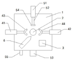
Fig. 1 is top view of the present invention.
The specific embodiment
Below in conjunction with drawings and Examples, the specific embodiment of the present invention is described in further detail.Following examples are used for illustrating the present invention, but are not used for limiting the scope of the invention.
As shown in Figure 1, novel tamping plant of the present invention, comprise workbench 1, platen 2, feeding mechanism 6, motor 3, mold mechanism and drawing-out mechanism, mold mechanism comprises mould, the first hydraulic jack 41 and the second hydraulic jack 42, mould comprises the first die blade 43 and the second die blade 44, the first die blade 43 and the second die blade 44 match, and the first die blade 43 is connected with the output of the second hydraulic jack 42 with the first hydraulic jack 41 by connecting rod respectively with the second die blade 44; Feeding mechanism 6 is arranged on the top of mould; Drawing-out mechanism comprises cylinder 51, push rod 52 and rewinding pond 53, push rod 52 one end are connected with the output of cylinder 51, push rod 52 other ends are arranged on a side of mould and in end, are provided with pushing block 54, on pushing block 54, are provided with cushion pad, and rewinding pond 53 is arranged on the bottom of workbench 1; Like this, the first hydraulic jack and the second hydraulic jack are controlled the first die blade and the complete mould of the closed formation of the second die blade, feeding mechanism is added to powder-type material in mould, platen carries out die mould to powder-type material, then controlling the first hydraulic jack and the second hydraulic jack exits the first die blade and the second die blade, cylinder is released the material of moulding from workbench, like this, can effectively avoid manually to its operation, effectively improve the security of using, be difficult for causing tong problem simultaneously; In addition, cushion pad can the damage of effectively anti-thrust block to mould.
Novel tamping plant of the present invention, drawing-out mechanism also comprises gauge tap, and gauge tap is connected with cylinder, the first hydraulic jack and the second hydraulic jack, and gauge tap is arranged on the bottom of workbench, and is provided with up pedal 55; Like this, control cylinder, the first hydraulic jack and the second hydraulic jack easily trampled by pin, completes exiting of material.
The above is only the preferred embodiment of the present invention; it should be pointed out that for those skilled in the art, do not departing under the prerequisite of the technology of the present invention principle; can also make some improvement and modification, these improve and modification also should be considered as protection scope of the present invention.
Claims (2)
1. a novel tamping plant, it is characterized in that, comprise workbench, platen, feeding mechanism, motor, mold mechanism and drawing-out mechanism, described mold mechanism comprises mould, the first hydraulic jack and the second hydraulic jack, described mould comprises the first die blade and the second die blade, described the first die blade and the second die blade match, and described the first die blade is connected with the output of the second hydraulic jack with described the first hydraulic jack by connecting rod respectively with the second die blade; Described feeding mechanism is arranged on the top of described mould; Described drawing-out mechanism comprises cylinder, push rod and rewinding pond, described push rod one end is connected with the output of described cylinder, the described push rod other end is arranged on a side of mould and is provided with pushing block in end, on described pushing block, is provided with cushion pad, and described rewinding pond is arranged on the bottom of workbench.
2. novel tamping plant as claimed in claim 1, it is characterized in that, described drawing-out mechanism also comprises gauge tap, described gauge tap is connected with described cylinder, the first hydraulic jack and the second hydraulic jack, described gauge tap is arranged on the bottom of described workbench, and is provided with up pedal.
Priority Applications (1)
| Application Number | Priority Date | Filing Date | Title |
|---|---|---|---|
| CN201310580753.XA CN103640244A (en) | 2013-11-20 | 2013-11-20 | Novel profiling device |
Applications Claiming Priority (1)
| Application Number | Priority Date | Filing Date | Title |
|---|---|---|---|
| CN201310580753.XA CN103640244A (en) | 2013-11-20 | 2013-11-20 | Novel profiling device |
Publications (1)
| Publication Number | Publication Date |
|---|---|
| CN103640244A true CN103640244A (en) | 2014-03-19 |
Family
ID=50245600
Family Applications (1)
| Application Number | Title | Priority Date | Filing Date |
|---|---|---|---|
| CN201310580753.XA Pending CN103640244A (en) | 2013-11-20 | 2013-11-20 | Novel profiling device |
Country Status (1)
| Country | Link |
|---|---|
| CN (1) | CN103640244A (en) |
Cited By (2)
| Publication number | Priority date | Publication date | Assignee | Title |
|---|---|---|---|---|
| CN107900340A (en) * | 2017-12-14 | 2018-04-13 | 东莞理工学院 | A kind of method and its heap-type mould using metal dust processing boss |
| CN108031850A (en) * | 2017-12-14 | 2018-05-15 | 东莞理工学院 | A kind of heap-type mechanism for metal dust processing boss |
Citations (8)
| Publication number | Priority date | Publication date | Assignee | Title |
|---|---|---|---|---|
| CN2887589Y (en) * | 2006-03-27 | 2007-04-11 | 杨崇传 | Powder moulding machine |
| CN101239506A (en) * | 2007-01-29 | 2008-08-13 | 常飞 | Biomass stalk briquetting machine |
| CN101391301A (en) * | 2008-11-10 | 2009-03-25 | 北京中科三环高技术股份有限公司 | Powder-feeding device and method in magnet forming process |
| CN102198464A (en) * | 2010-03-25 | 2011-09-28 | 河南鸿马实业有限公司 | Steel tie rod molding press |
| JP2012071324A (en) * | 2010-09-28 | 2012-04-12 | Hitachi Powdered Metals Co Ltd | Powder molding die device |
| CN203109225U (en) * | 2013-03-07 | 2013-08-07 | 北京麦戈龙永磁材料有限公司 | Novel tamping plant assembly |
| CN203109226U (en) * | 2013-03-07 | 2013-08-07 | 北京麦戈龙永磁材料有限公司 | Novel tamping plant |
| CN203622996U (en) * | 2013-11-20 | 2014-06-04 | 苏州蓝王机床工具科技有限公司 | Novel pressing and forming device |
-
2013
- 2013-11-20 CN CN201310580753.XA patent/CN103640244A/en active Pending
Patent Citations (8)
| Publication number | Priority date | Publication date | Assignee | Title |
|---|---|---|---|---|
| CN2887589Y (en) * | 2006-03-27 | 2007-04-11 | 杨崇传 | Powder moulding machine |
| CN101239506A (en) * | 2007-01-29 | 2008-08-13 | 常飞 | Biomass stalk briquetting machine |
| CN101391301A (en) * | 2008-11-10 | 2009-03-25 | 北京中科三环高技术股份有限公司 | Powder-feeding device and method in magnet forming process |
| CN102198464A (en) * | 2010-03-25 | 2011-09-28 | 河南鸿马实业有限公司 | Steel tie rod molding press |
| JP2012071324A (en) * | 2010-09-28 | 2012-04-12 | Hitachi Powdered Metals Co Ltd | Powder molding die device |
| CN203109225U (en) * | 2013-03-07 | 2013-08-07 | 北京麦戈龙永磁材料有限公司 | Novel tamping plant assembly |
| CN203109226U (en) * | 2013-03-07 | 2013-08-07 | 北京麦戈龙永磁材料有限公司 | Novel tamping plant |
| CN203622996U (en) * | 2013-11-20 | 2014-06-04 | 苏州蓝王机床工具科技有限公司 | Novel pressing and forming device |
Cited By (3)
| Publication number | Priority date | Publication date | Assignee | Title |
|---|---|---|---|---|
| CN107900340A (en) * | 2017-12-14 | 2018-04-13 | 东莞理工学院 | A kind of method and its heap-type mould using metal dust processing boss |
| CN108031850A (en) * | 2017-12-14 | 2018-05-15 | 东莞理工学院 | A kind of heap-type mechanism for metal dust processing boss |
| CN108031850B (en) * | 2017-12-14 | 2019-08-13 | 东莞理工学院 | A kind of heap-type mechanism for metal powder processing boss |
Similar Documents
| Publication | Publication Date | Title |
|---|---|---|
| CN203622996U (en) | Novel pressing and forming device | |
| CN203331182U (en) | Demolding machine | |
| CN204019188U (en) | A kind of band saw machine clamping device | |
| CN203438191U (en) | Nail pulling machine | |
| CN103640244A (en) | Novel profiling device | |
| CN203109226U (en) | Novel tamping plant | |
| CN204431461U (en) | The pouring can of a kind of liftable cast and there is the running gate system of this pouring can | |
| CN204413055U (en) | ceramic core accurate positioning device | |
| CN207888942U (en) | A kind of ceramic tile cutting clamper quickly accommodated | |
| CN203356460U (en) | Pipe carrying mechanism of pipe punch forming machine | |
| CN103723490B (en) | A kind of for carrying the conveying mechanism of the steel wire after putting on and handle | |
| CN103286899B (en) | Stripper apparatus | |
| CN203076729U (en) | Screw grinder with adjustable length | |
| CN203282318U (en) | Automatic fixed-length cutting and graining machine for hose | |
| CN202621916U (en) | Magnetic element forming machine | |
| CN205319872U (en) | Reshaping mechanism | |
| CN203282633U (en) | Anti-blackout demoulding machine of flat vulcanizing machine | |
| CN203895731U (en) | Hydraulic wire crimping tool with cutting function | |
| CN203357584U (en) | Plank hot press | |
| CN203527911U (en) | Hand-operated stamping device | |
| CN202590740U (en) | Anti-squeezing-hand pressing machine for production of cubic boron nitride (CBN) | |
| CN204725795U (en) | Plastics I-shaped alternate water injection mouth removes from device | |
| CN204220867U (en) | Automatically the steel bar thick machine of fixture is opened | |
| CN202448293U (en) | Hydraulic moulding automatic film conveying auxiliary device | |
| CN103786366A (en) | Novel grinding wheel mould |
Legal Events
| Date | Code | Title | Description |
|---|---|---|---|
| PB01 | Publication | ||
| PB01 | Publication | ||
| C10 | Entry into substantive examination | ||
| SE01 | Entry into force of request for substantive examination | ||
| C02 | Deemed withdrawal of patent application after publication (patent law 2001) | ||
| WD01 | Invention patent application deemed withdrawn after publication |
Application publication date: 20140319 |