CN102198464A - Steel tie rod molding press - Google Patents
Steel tie rod molding press Download PDFInfo
- Publication number
- CN102198464A CN102198464A CN2010101322589A CN201010132258A CN102198464A CN 102198464 A CN102198464 A CN 102198464A CN 2010101322589 A CN2010101322589 A CN 2010101322589A CN 201010132258 A CN201010132258 A CN 201010132258A CN 102198464 A CN102198464 A CN 102198464A
- Authority
- CN
- China
- Prior art keywords
- frame
- upper die
- hydraulic pump
- die
- hydraulic cylinder
- Prior art date
- Legal status (The legal status is an assumption and is not a legal conclusion. Google has not performed a legal analysis and makes no representation as to the accuracy of the status listed.)
- Pending
Links
Images
Landscapes
- Press Drives And Press Lines (AREA)
Abstract
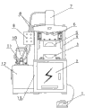
The invention discloses a steel tie rod molding press. An electric cabinet is arranged at the lower part of a frame, a control panel is arranged on a support frame of the frame, a hydraulic pump and a motor connected with the hydraulic pump are positioned on one side of the frame, a reversing valve is arranged on the hydraulic pump, the reversing valve is connected with a hydraulic cylinder at the upper end of the frame through an oil pipe, the lower end of the hydraulic cylinder is connected with an upper die holder, an upper die is arranged at the lower end of the upper die holder, and a lower die is arranged at the position opposite to the upper die and positioned on a support plate of the frame below the lower die; and the inner side of an upper supporting pillar of the frame is provided with a slipway, the upper die holder is provided with a chute matched with the slipway, and the upper die can move up and down along the slipway. The upper die and the lower die are fixed through screws, and pins are not used, so deviation is not caused. The upper die moves along the slipway, so blocking is not caused. The corresponding surfaces of the upper die and the lower die are concave spherical surfaces, so that small-diameter steel pipes are processed, namely the two ends of the steel pipes are flattened, and then the steel pipes are perforated to facilitate connection.
Description
Technical field
The invention belongs to pressing equipment, relate in particular to a kind of steel tie-rod forming press.
Background technology
The weak point of present steel tie-rod forming press is exactly that tonnage is little, and is inapplicable for large-scale steel pipe and thick walled steel tube.
Summary of the invention
The object of the present invention is to provide a kind of simple in structurely, easy to operate,, and stuck phenomenon can not occur by slideway control patrix running orbit.
The present invention is achieved by the following technical solutions:
A kind of steel tie-rod forming press, comprise frame, electric cabinet, control panel, motor, hydraulic pump, hydraulic cylinder, upper die and lower die, described electric cabinet is positioned at the bottom of frame, described control panel is installed on the bracing frame of frame, hydraulic pump and the motor that is connected with hydraulic pump are positioned at a side of frame, hydraulic pump is provided with reversal valve, reversal valve links to each other with the hydraulic cylinder that is installed in the frame upper end by oil pipe, the lower end of hydraulic cylinder is connected with upper bolster, described patrix is installed in the lower end of upper bolster, and described counterdie is installed in patrix position opposite position and is positioned on the gripper shoe of methods, rack under it; Inboard at the upper rack support column is provided with slideway, and upper bolster is provided with the chute that matches with slideway, and can move up and down along slideway.
Corresponding of described upper die and lower die is concave spherical surface.
Described electric cabinet is provided with connected floor push.
Advantage of the present invention is: upper die and lower die are to fix by screw among the present invention, and no pin deviation can not occur.During the patrix operation is not by lead, but slideway, and stuck phenomenon can not appear.Corresponding of upper die and lower die is concave spherical surface, can process the following steel pipe of diameter 140mm (thickness of steel pipe is less than 6mm), just the steel pipe two ends is flattened, and punching is convenient to connect (using mainly as the steel tie-rod above the steel house) then.
Description of drawings
Figure is a structural representation of the present invention.
The specific embodiment
Embodiment: steel tie-rod forming press as shown in the figure, comprise frame 13, electric cabinet 2, control panel 9, motor 10, hydraulic pump 12, hydraulic cylinder 7, patrix 5 and counterdie 3, described electric cabinet 2 is positioned at the bottom of frame 13, and electric cabinet 2 is provided with connected floor push 1.Described control panel 9 is installed on the bracing frame of frame 13.Hydraulic pump and the motor that is connected with hydraulic pump are positioned at a side of frame 13, hydraulic pump 12 is provided with reversal valve 11, reversal valve 11 links to each other with the hydraulic cylinder 7 that is installed in frame 13 upper ends by oil pipe 8, the lower end of hydraulic cylinder 7 is connected with upper bolster 6, and described patrix 5 is installed in the lower end of upper bolster 6 by screw; Described counterdie 3 is installed in patrix 5 position opposite positions and is positioned on the gripper shoe of methods, rack 13 under it.Corresponding of described patrix 5 and counterdie 3 is concave spherical surface, and the radian of concave spherical surface is decided because of the part dimension of concrete processing.Inboard at frame 13 upper support posts is provided with slideway 4, and upper bolster 6 is provided with the chute that matches with slideway 4, and can move up and down along slideway.Described electric cabinet 2 is provided with connected floor push 1.
Floor push 1 is controlled die mould, and patrix is descending when stepping on floor push 1 starts working, and after die mould is finished, unclamps floor push, and patrix gos up, and finishes a working cycles.
Claims (3)
1. steel tie-rod forming press, comprise frame, electric cabinet, control panel, motor, hydraulic pump, hydraulic cylinder, upper die and lower die, it is characterized in that: described electric cabinet is positioned at the bottom of frame, described control panel is installed on the bracing frame of frame, hydraulic pump and the motor that is connected with hydraulic pump are positioned at a side of frame, hydraulic pump is provided with reversal valve, reversal valve links to each other with the hydraulic cylinder that is installed in the frame upper end by oil pipe, the lower end of hydraulic cylinder is connected with upper bolster, described patrix is installed in the lower end of upper bolster, and described counterdie is installed in patrix position opposite position and is positioned on the gripper shoe of methods, rack under it; Inboard at the upper rack support column is provided with slideway, and upper bolster is provided with the chute that matches with slideway, and can move up and down along slideway.
2. steel tie-rod forming press according to claim 1 is characterized in that: corresponding of described upper die and lower die is concave spherical surface.
3. steel tie-rod forming press according to claim 1, it is characterized in that: described electric cabinet is provided with connected floor push.
Priority Applications (1)
| Application Number | Priority Date | Filing Date | Title |
|---|---|---|---|
| CN2010101322589A CN102198464A (en) | 2010-03-25 | 2010-03-25 | Steel tie rod molding press |
Applications Claiming Priority (1)
| Application Number | Priority Date | Filing Date | Title |
|---|---|---|---|
| CN2010101322589A CN102198464A (en) | 2010-03-25 | 2010-03-25 | Steel tie rod molding press |
Publications (1)
| Publication Number | Publication Date |
|---|---|
| CN102198464A true CN102198464A (en) | 2011-09-28 |
Family
ID=44659603
Family Applications (1)
| Application Number | Title | Priority Date | Filing Date |
|---|---|---|---|
| CN2010101322589A Pending CN102198464A (en) | 2010-03-25 | 2010-03-25 | Steel tie rod molding press |
Country Status (1)
| Country | Link |
|---|---|
| CN (1) | CN102198464A (en) |
Cited By (4)
| Publication number | Priority date | Publication date | Assignee | Title |
|---|---|---|---|---|
| CN103506458A (en) * | 2013-09-18 | 2014-01-15 | 梁招仙 | Simple metal cap stamping mechanism |
| CN103640244A (en) * | 2013-11-20 | 2014-03-19 | 苏州蓝王机床工具科技有限公司 | Novel profiling device |
| CN106965476A (en) * | 2017-02-23 | 2017-07-21 | 江苏铭格锻压设备有限公司 | Integral hydraulic press |
| US10010920B2 (en) | 2010-07-27 | 2018-07-03 | Ford Global Technologies, Llc | Method to improve geometrical accuracy of an incrementally formed workpiece |
Citations (5)
| Publication number | Priority date | Publication date | Assignee | Title |
|---|---|---|---|---|
| US6216508B1 (en) * | 1998-01-29 | 2001-04-17 | Amino Corporation | Apparatus for dieless forming plate materials |
| CN2595558Y (en) * | 2002-11-06 | 2003-12-31 | 江予进 | Hydraulic press machine for motor vehicle license plate |
| CN201067974Y (en) * | 2007-07-21 | 2008-06-04 | 山西焦煤集团有限责任公司 | Pipe clip tamping machine |
| CN201394915Y (en) * | 2009-04-20 | 2010-02-03 | 张元杰 | Slab box type four-guiding rail pressure machine |
| CN201659185U (en) * | 2010-03-25 | 2010-12-01 | 河南鸿马实业有限公司 | Steel tie bar molding press |
-
2010
- 2010-03-25 CN CN2010101322589A patent/CN102198464A/en active Pending
Patent Citations (5)
| Publication number | Priority date | Publication date | Assignee | Title |
|---|---|---|---|---|
| US6216508B1 (en) * | 1998-01-29 | 2001-04-17 | Amino Corporation | Apparatus for dieless forming plate materials |
| CN2595558Y (en) * | 2002-11-06 | 2003-12-31 | 江予进 | Hydraulic press machine for motor vehicle license plate |
| CN201067974Y (en) * | 2007-07-21 | 2008-06-04 | 山西焦煤集团有限责任公司 | Pipe clip tamping machine |
| CN201394915Y (en) * | 2009-04-20 | 2010-02-03 | 张元杰 | Slab box type four-guiding rail pressure machine |
| CN201659185U (en) * | 2010-03-25 | 2010-12-01 | 河南鸿马实业有限公司 | Steel tie bar molding press |
Non-Patent Citations (1)
| Title |
|---|
| 王遵华等,: "摩擦压力机用矩形模座的设计与应用", 《锻压机械》 * |
Cited By (4)
| Publication number | Priority date | Publication date | Assignee | Title |
|---|---|---|---|---|
| US10010920B2 (en) | 2010-07-27 | 2018-07-03 | Ford Global Technologies, Llc | Method to improve geometrical accuracy of an incrementally formed workpiece |
| CN103506458A (en) * | 2013-09-18 | 2014-01-15 | 梁招仙 | Simple metal cap stamping mechanism |
| CN103640244A (en) * | 2013-11-20 | 2014-03-19 | 苏州蓝王机床工具科技有限公司 | Novel profiling device |
| CN106965476A (en) * | 2017-02-23 | 2017-07-21 | 江苏铭格锻压设备有限公司 | Integral hydraulic press |
Similar Documents
| Publication | Publication Date | Title |
|---|---|---|
| CN201659185U (en) | Steel tie bar molding press | |
| CN204396615U (en) | Tubing is to hole punching machine | |
| CN102198464A (en) | Steel tie rod molding press | |
| CN202129337U (en) | Digital-control multi-position punching machine | |
| CN204018587U (en) | The position limiting structure of discharge arm in numerical control sheet material bender | |
| CN204308037U (en) | A kind of housing flanger | |
| CN203236723U (en) | Bean curd forming squeezer | |
| CN104259263A (en) | Numerical control board bending machine | |
| CN101758630A (en) | Double-action thick plate stretching hydraulic machine | |
| CN203170783U (en) | Oil tube end portion thickening machine | |
| CN204365733U (en) | Horizontal automatic guide radial compression machine | |
| CN201091894Y (en) | Metal pipe internal hole flanging machine | |
| CN106270255A (en) | It is applied to the jacking device for discharging of nut processing | |
| CN211161415U (en) | Numerical control press convenient to material loading | |
| CN202701149U (en) | Bend die | |
| CN204094908U (en) | A kind of internal-suction type circle internal mold flue forming machine | |
| CN206253495U (en) | A kind of reverse single processing assembly of steel tower corner iron | |
| CN203695740U (en) | Punching processing device for valve inside of wheel rim | |
| CN203209577U (en) | Novel combined steel bar bending and hooping machine | |
| CN105598423A (en) | Metal mold casting demolding machine for tubular shells | |
| CN209648009U (en) | A kind of apparatus for shaping of automated arm part | |
| CN206425435U (en) | Many size flat tube necking dies and device | |
| CN102641918B (en) | Horizontal type bending machine used for forming annular piece | |
| CN204018573U (en) | The workbench of numerical control bender | |
| CN201304440Y (en) | A pipe liquid-filling forming mould frame structure |
Legal Events
| Date | Code | Title | Description |
|---|---|---|---|
| C06 | Publication | ||
| PB01 | Publication | ||
| C10 | Entry into substantive examination | ||
| SE01 | Entry into force of request for substantive examination | ||
| C12 | Rejection of a patent application after its publication | ||
| RJ01 | Rejection of invention patent application after publication |
Application publication date: 20110928 |