CN103619567A - Automated ply layup system and method of laying up - Google Patents
Automated ply layup system and method of laying up Download PDFInfo
- Publication number
- CN103619567A CN103619567A CN201280030394.4A CN201280030394A CN103619567A CN 103619567 A CN103619567 A CN 103619567A CN 201280030394 A CN201280030394 A CN 201280030394A CN 103619567 A CN103619567 A CN 103619567A
- Authority
- CN
- China
- Prior art keywords
- laminate
- end effector
- robot
- instrument
- utilize
- Prior art date
- Legal status (The legal status is an assumption and is not a legal conclusion. Google has not performed a legal analysis and makes no representation as to the accuracy of the status listed.)
- Pending
Links
Images


Classifications
-
- B—PERFORMING OPERATIONS; TRANSPORTING
- B29—WORKING OF PLASTICS; WORKING OF SUBSTANCES IN A PLASTIC STATE IN GENERAL
- B29C—SHAPING OR JOINING OF PLASTICS; SHAPING OF MATERIAL IN A PLASTIC STATE, NOT OTHERWISE PROVIDED FOR; AFTER-TREATMENT OF THE SHAPED PRODUCTS, e.g. REPAIRING
- B29C70/00—Shaping composites, i.e. plastics material comprising reinforcements, fillers or preformed parts, e.g. inserts
- B29C70/04—Shaping composites, i.e. plastics material comprising reinforcements, fillers or preformed parts, e.g. inserts comprising reinforcements only, e.g. self-reinforcing plastics
- B29C70/28—Shaping operations therefor
- B29C70/30—Shaping by lay-up, i.e. applying fibres, tape or broadsheet on a mould, former or core; Shaping by spray-up, i.e. spraying of fibres on a mould, former or core
- B29C70/38—Automated lay-up, e.g. using robots, laying filaments according to predetermined patterns
-
- B—PERFORMING OPERATIONS; TRANSPORTING
- B25—HAND TOOLS; PORTABLE POWER-DRIVEN TOOLS; MANIPULATORS
- B25J—MANIPULATORS; CHAMBERS PROVIDED WITH MANIPULATION DEVICES
- B25J13/00—Controls for manipulators
- B25J13/08—Controls for manipulators by means of sensing devices, e.g. viewing or touching devices
- B25J13/085—Force or torque sensors
-
- B—PERFORMING OPERATIONS; TRANSPORTING
- B25—HAND TOOLS; PORTABLE POWER-DRIVEN TOOLS; MANIPULATORS
- B25J—MANIPULATORS; CHAMBERS PROVIDED WITH MANIPULATION DEVICES
- B25J15/00—Gripping heads and other end effectors
-
- B—PERFORMING OPERATIONS; TRANSPORTING
- B25—HAND TOOLS; PORTABLE POWER-DRIVEN TOOLS; MANIPULATORS
- B25J—MANIPULATORS; CHAMBERS PROVIDED WITH MANIPULATION DEVICES
- B25J15/00—Gripping heads and other end effectors
- B25J15/0085—Gripping heads and other end effectors with means for applying an electrostatic force on the object to be gripped
-
- B—PERFORMING OPERATIONS; TRANSPORTING
- B25—HAND TOOLS; PORTABLE POWER-DRIVEN TOOLS; MANIPULATORS
- B25J—MANIPULATORS; CHAMBERS PROVIDED WITH MANIPULATION DEVICES
- B25J15/00—Gripping heads and other end effectors
- B25J15/06—Gripping heads and other end effectors with vacuum or magnetic holding means
- B25J15/0616—Gripping heads and other end effectors with vacuum or magnetic holding means with vacuum
-
- B—PERFORMING OPERATIONS; TRANSPORTING
- B25—HAND TOOLS; PORTABLE POWER-DRIVEN TOOLS; MANIPULATORS
- B25J—MANIPULATORS; CHAMBERS PROVIDED WITH MANIPULATION DEVICES
- B25J19/00—Accessories fitted to manipulators, e.g. for monitoring, for viewing; Safety devices combined with or specially adapted for use in connection with manipulators
- B25J19/02—Sensing devices
- B25J19/021—Optical sensing devices
- B25J19/022—Optical sensing devices using lasers
-
- B—PERFORMING OPERATIONS; TRANSPORTING
- B25—HAND TOOLS; PORTABLE POWER-DRIVEN TOOLS; MANIPULATORS
- B25J—MANIPULATORS; CHAMBERS PROVIDED WITH MANIPULATION DEVICES
- B25J19/00—Accessories fitted to manipulators, e.g. for monitoring, for viewing; Safety devices combined with or specially adapted for use in connection with manipulators
- B25J19/02—Sensing devices
- B25J19/021—Optical sensing devices
- B25J19/023—Optical sensing devices including video camera means
-
- B—PERFORMING OPERATIONS; TRANSPORTING
- B25—HAND TOOLS; PORTABLE POWER-DRIVEN TOOLS; MANIPULATORS
- B25J—MANIPULATORS; CHAMBERS PROVIDED WITH MANIPULATION DEVICES
- B25J9/00—Programme-controlled manipulators
- B25J9/16—Programme controls
-
- B—PERFORMING OPERATIONS; TRANSPORTING
- B25—HAND TOOLS; PORTABLE POWER-DRIVEN TOOLS; MANIPULATORS
- B25J—MANIPULATORS; CHAMBERS PROVIDED WITH MANIPULATION DEVICES
- B25J9/00—Programme-controlled manipulators
- B25J9/16—Programme controls
- B25J9/1694—Programme controls characterised by use of sensors other than normal servo-feedback from position, speed or acceleration sensors, perception control, multi-sensor controlled systems, sensor fusion
- B25J9/1697—Vision controlled systems
-
- Y—GENERAL TAGGING OF NEW TECHNOLOGICAL DEVELOPMENTS; GENERAL TAGGING OF CROSS-SECTIONAL TECHNOLOGIES SPANNING OVER SEVERAL SECTIONS OF THE IPC; TECHNICAL SUBJECTS COVERED BY FORMER USPC CROSS-REFERENCE ART COLLECTIONS [XRACs] AND DIGESTS
- Y10—TECHNICAL SUBJECTS COVERED BY FORMER USPC
- Y10T—TECHNICAL SUBJECTS COVERED BY FORMER US CLASSIFICATION
- Y10T156/00—Adhesive bonding and miscellaneous chemical manufacture
- Y10T156/10—Methods of surface bonding and/or assembly therefor
Landscapes
- Engineering & Computer Science (AREA)
- Robotics (AREA)
- Mechanical Engineering (AREA)
- Chemical & Material Sciences (AREA)
- Composite Materials (AREA)
- Human Computer Interaction (AREA)
- Multimedia (AREA)
- Physics & Mathematics (AREA)
- Optics & Photonics (AREA)
- Moulding By Coating Moulds (AREA)
- Manipulator (AREA)
- Processing And Handling Of Plastics And Other Materials For Molding In General (AREA)
Abstract
An automated ply layup system and method using a robot (22) and an end effector (20) for picking plies (48) from a kit and placing the plies at predetermined locations on a tool (28).
Description
Technical field
The disclosure relates generally to the manufacture of the layer structure that layer structure especially forms by composite, and more specifically relates to for automatically lay the system of laminate on instrument.
Background technology
During the making of large-sized layer structure, the laminate in groups that is arranged to case (kit) can be sequentially laid on the specific location of instrument, so that strengthening, sclerosis or otherwise provide architectural characteristic or the Performance Characteristics of expectation for structure.In some applications, the use of laminate case may be effectively, because it is without many relatively little laminates are laid on to the automatic band installation apparatus in regional area.Such as but not limited to, in the situation that expectation utilizes composite filled thing to fill the longeron of fuselage and the gap between framework, can use laminate case.The filler laminate that filler comprises one group of lamination, before whole laminates are laid on above filler, filler laminate is sequentially placed on instrument.Filler laminate can be placed in the groove in instrument, and described groove is shaped especially and is positioned to form the filler of certain shape when groove is filled full laminate.In the past, by manually carrying out process of deployment.
In other application, may need artificial laying technology.For example, may need by laminate (such as compound plate) be laid on substrate relative to each other accurately in position.Utilize artificial laying technology, technical staff must be placed on each laminate on substrate at the accurate location place with respect to other laminates.And artificial laying technology need to be placed laminate one at a time, and the size of the size-constrained laminate that can manual manipulation in technical staff of laminate.In other application, at laminate material when by AFP machine processing relatively frangible and/or suffer wrinkling, crease or tear in the situation that, can need artificial laying.For example, by by the grid application of thin copper foil sheet in the outer skin of aircraft, can realize the anti-lightning strike protection of aircraft.By being manually laid in process of deployment, may suffer hundreds of quite little thin copper foil sheets wrinkling, that cave in, crease or tear, with the form assembling grid of.
Above-mentioned artificial laying technology is consuming time, labour-intensive, and may be not suitable for higher production environment.Therefore, exist the following needs of paving system automatically, this automatic paving system reduces hand labor and laying time, and the placement accurately and reliably of material laminate on substrate (such as instrument) is provided.Also exist allow placing larger laminate to reduce the needs of the laying process of the laminate sum that need to be placed to form structure.
Summary of the invention
Disclosed embodiment provides the automatic paving system that is suitable for laying laminate in groups, and laminate is in groups such as being into the filler, compound plate of case and for the laminate of the other types of various application.The end effector of controlling by robot automatically performs following process, in laminate case (ply kit), selects in order the laminate of expectation, selected laminate is passed to instrument, and laminate is placed on to the proper position on instrument.End effector is visually identified the correct laminate that will promote from case, and the feature that is used to locate laminate during laminate is placed and compressed on testing tool.It is wrinkling that this system can reduce or eliminate laminate, and the control of more accurate process of deployment can be provided.End effector can pick up and place various laminates, such as, but not limited to thermoplastic, preimpregnation material, metal forming and tack coat etc.End effector can be used to the regional area of preliminary examination instrument before laminate is placed on instrument, or the laminate being placed in rear inspection is to guarantee appropriate alignment.
According to a disclosed embodiment, provide for composite layered plate being laid on to the system of preselected position.End effector in robot promotes laminate, and laminate is placed on to preselected position.Device for the position of the laminate on recording terminal end actuator is provided, and has placed laminate with controller control and the end effector of tape deck coupling.End effector can comprise the clamper of vacuumizing, and this clamper thinks that for being raised at laminate placement clamps this laminate while preparing.Tape deck can comprise floor-mounted camera, and it is for observing the laminate on end effector.This system can also be included in the video camera on end effector, and this video camera and controller coupling, observe this laminate, and controller can comprise for identify and select the software of laminate from a plurality of laminates before being promoted by end effector at laminate.This system can also be included in the detector on end effector, and this detector is for detecting the position of the feature of the placement be used to adjust laminate at placement location place.In one embodiment, described detector can comprise 3-D laser scanner.When laminate is placed end effector in Shi, robot for thrust is applied to laminate, and this system is also included in the sensor on end effector, and this sensor is for the size of sensing thrust.
According to another embodiment, provide for laminate is laid on to the system on substrate automatically.This system comprises end effector and robot, and described end effector is for being placed on substrate by each of laminate, and described robot is used for handling end effector.Detector is provided on end effector, for the feature on testing tool.Control end effector with the controller of detector coupling in robot and laminate is placed to the position of the detected feature based on substrate on substrate.In one embodiment, detector is laser scanner, and this laser scanner is suitable for the surface of scanning substrate.This system can also be included in the video camera on end effector, and it is for recording the image of laminate before being raised at laminate, and controller can comprise for identifying by the object identification software of the image of camera record.This system can also comprise the video camera for the image of the laminate on recording terminal end actuator, and its middle controller is operable as the position of determining the laminate on end effector after laminate is raised.
According to another embodiment, provide the method that laminate is laid on to the pre-position on substrate.The method comprises picks up laminate, laminate is moved to the region in the precalculated position in adjacent substrates, the precalculated position orientation that laminate will be placed with respect to laminate, and laminate is placed on to the pre-position on substrate.End effector is used to pick up laminate, and is moved to the region of adjacent substrates.End effector is used to detect the feature that represents the precalculated position that laminate will be placed on substrate.End effector is also used to the feature based on detected and laminate is placed on substrate.Picking up laminate can comprise by laminate being kept and clamps described laminate on actuator endways against end effector with vacuum.Utilize the robotic manipulator of automatically controlling to carry out the region that end effector is moved to adjacent tools.The feature of utilizing end effector to detect on substrate comprises the surface of using noncontact scanner scanning substrate.The method can also comprise utilizes end effector that laminate is compressed against substrate, and utilizes the sensor on end effector to come sensing by end effector, to be applied to the thrust of laminate.
According to another embodiment, provide the method for manufacturing aircraft composite construction.The method comprises provides a plurality of composite layered plates, and the end effector that utilizes robot to control picks up in laminate.The method also comprises the position of determining the laminate on end effector, and utilizes end effector laminate to be moved to the region of instrument.End effector is used to the position of the laminate based on end effector and laminate is placed on instrument.End effector can also be used to the laminate that identification will be picked.
According to another embodiment, the method that reduces making multi-layer sheet composite construction required time comprises: utilize the band of automatically controlling to lay machine and be laid on a route that forms the composite band of laminate on instrument, and utilize the end effector of robot control that laminate is placed on the regional area of instrument.
According to another embodiment, provide laminate has been laid on to the method on substrate, the method comprises utilizes electricity absorption clamper clamping laminate, and the laminate being held is placed on substrate.Utilize electricity absorption clamper clamping laminate to comprise by produce Electrostatic Absorption power between clamper and laminate laminate is adsorbed to clamper.The laminate being held is placed on substrate and is comprised: the laminate that utilizes robotic manipulator to move to be held with substrate contacts, and discharge laminate from electricity absorption clamper.Discharge laminate and comprise the Electrostatic Absorption power of eliminating between clamper and laminate.Producing Electrostatic Absorption power comprises: on clamper, produce electrostatic field, and utilize electrostatic field on laminate, to induce electrostatic charge.
According to another embodiment, provide the laminate of conductive metal foil has been laid on to the method on aircraft skin.The method comprises utilizes end effector to pick up laminate, comprises and utilizes Electrostatic Absorption power clamping laminate, and end effector is moved to the region on covering.The method also comprises utilizes end effector that laminate is placed on covering.Laminate is placed on and on covering, comprises the Electrostatic Absorption power that clamps laminate on end effector that is released in.Clamping laminate comprises: on clamper, produce electrostatic field, and utilize electrostatic field on laminate, to induce electrostatic charge.
According to another embodiment, provide for laminate being laid on to the system on substrate, it comprises end effector and robotic manipulator, described end effector comprises that described robotic manipulator is used for handling end effector for utilizing Electrostatic Absorption power to clamp releasedly the electrostatic clamp device of laminate.This system also comprises the controller being programmed, and it is for the operation of robot brain device people's executor and electrostatic clamp device.Electrostatic clamp device comprises a plurality of positive and negative electrode pad replacing being suitable for Electric source coupling.Clamper comprises backing plate, and electrode pad is positioned on backing plate.Polymer coating is coated electrode pole plate protectively.This system also comprises for the device of the position of the laminate on recording terminal end actuator and the detector on actuator endways, the feature on the substrate that this detector will be placed for detection of laminate.
According to an aspect of the present invention, provide for composite layered plate being laid on to the system of preselected position, this system comprises: robot; In robot for promoting laminate and laminate being placed on to the end effector of preselected position; The device that is used for the position of the laminate on recording terminal end actuator; And with the controller of position recording device coupling, its for control and end effector laminate is placed on to described position.
Advantageously, in this system, end effector comprises the clamper of vacuumizing, and it is for clamping laminate.
Advantageously, in this system, end effector comprises electricity absorption clamper, and it is for clamping laminate.
Advantageously, in this system, electricity absorption clamper comprises one group of electrode pad, its be suitable for for induce the Electric source coupling of electrostatic charge on laminate.
Advantageously, in this system, position recording device comprises floor-mounted camera, and it is for the laminate on imaging end effector.
Advantageously, this system is also included in the video camera on end effector, this video camera and controller coupling were observed this laminate before being promoted by end effector at laminate, and its middle controller comprises for identify and select the software of described laminate from a plurality of laminates.
Advantageously, this system is also included in the detector on end effector, and it is for detection of the relevant feature in the position that will be placed with laminate.
Advantageously, in this system, characteristic position detection means is laser scanner.
Advantageously, in this system, when laminate is placed on instrument, end effector and robot are applied to laminate by thrust, and this system is also included in the sensor on end effector, and this sensor is for the size of sensing thrust.
According to a further aspect in the invention, provide for laminate is laid on to the system on substrate automatically, this system comprises: end effector, and it is for being placed on substrate by each laminate; Detector on actuator endways, it is for detection of the relevant feature in the position that will be placed with laminate on substrate; Robot, it is for handling end effector; And with the controller of detector and robot coupling, this controller is placed on laminate the position of the detected feature based on substrate on substrate for controlling end effector.
Advantageously, in this system, detector is laser scanner, and it is suitable for the surface of scanning substrate.
Advantageously, this system is also included in the video camera on end effector, and it is for recording the image of laminate before being raised at laminate, and its middle controller comprises for identifying by the object identification software of the image of camera record.
Advantageously, this system also comprises the video camera for the image of the laminate on recording terminal end actuator, and its middle controller is operable as the position of determining the laminate on end effector.
Advantageously, this system is also included on end effector for clamping the holder fixed by vacuum of laminate; And with the vacuum system of holder fixed by vacuum coupling.
Advantageously, this system is also included in the electricity absorption clamper on end effector, and it is for utilizing Electrostatic Absorption power clamping laminate.
Advantageously, in this system, end effector is operable as laminate is compressed against substrate, and this system is also included in the power sensor on end effector, and it puts on the thrust of laminate for sensing.
According to a further aspect in the invention, provide the method that laminate is laid on to the pre-position on substrate, the method comprises: pick up laminate; Laminate is moved to the region in the precalculated position that contiguous laminate will be placed; The precalculated position orientation that laminate will be placed with respect to laminate; And the laminate being oriented is placed on to the pre-position on substrate.
Advantageously, in the method, utilize Electrostatic Absorption power clamping laminate to carry out and pick up laminate.
Advantageously, in the method, by carrying out and pick up laminate with end effector clamping laminate, by end effector being moved to the region in contiguous precalculated position, carry out mobile laminate, and utilize end effector to carry out placement laminate.
Advantageously, the method also comprises, utilize end effector to detect the relevant feature in position that will be placed with laminate, wherein utilizing end effector to place laminate is feature based on detected, and utilizes the robotic manipulator of automatically controlling to carry out the region that end effector is moved to contiguous precalculated position.
Advantageously, in the method, utilize end effector detected characteristics to comprise the surface of using untouchable scanner scanning substrate.
Advantageously, the method also comprises: utilize end effector that laminate is compressed against substrate; And utilize the sensor on end effector to come sensing by end effector, to be put on the thrust of laminate.
Advantageously, in the method, substrate is instrument, and wherein the position on substrate is the groove in instrument.
Advantageously, the method also comprises: utilize end effector identify will be picked and mobile laminate.
According to a further aspect in the invention, provide the method for manufacturing aircraft composite construction, the method comprises: a plurality of composite layered plates are provided; The end effector that utilizes robot to control picks up in laminate; Determine the position of the laminate on end effector; And the position of the laminate based on end effector, utilize end effector that laminate is placed on to pre-position.Advantageously, in the method, the position of determining the laminate on end effector comprises the image of the laminate on recording terminal end actuator.Advantageously, the method utilizes end effector that laminate is moved to instrument.Advantageously, in the method, pick up laminate and comprise and utilize Electrostatic Absorption power on actuator, to clamp laminate endways.
Advantageously, the method also comprises: utilize end effector identify will be picked laminate in one.
Advantageously, in the method, by the image that utilizes end effector to record the image of laminate and utilize image recognition software to identify to be recorded, carry out in the laminate that identification will be picked.
According to a further aspect in the invention, provide to reduce and made the multi-layer sheet composite construction method of required time, the method comprises: utilize the band of automatically controlling to lay machine and be laid on the route that forms the composite band of laminate on instrument; And the end effector that utilizes robot to control is placed on laminate on the regional area of instrument.
Advantageously, in the method, the laminate of being placed by end effector forms in compound plate and filler.
Advantageously, in the method, lay the route of machine laying band at band before, end effector is placed on laminate on instrument.
Advantageously, in the method, band is laid the route that machine is laid band on the laminate of being placed by end effector.
According to a further aspect in the invention, provide laminate is laid on to the method on substrate, the method comprises: utilize electricity absorption clamper clamping laminate; And the laminate being held is placed on substrate.
Advantageously, in the method, utilize electricity absorption clamper clamping laminate to comprise: by produce Electrostatic Absorption power between clamper and laminate, laminate to be adsorbed to clamper.
Advantageously, in the method, the laminate being held is placed on substrate and is comprised: the laminate that utilizes robotic manipulator to move to be held with substrate contacts, and discharge laminate from electricity absorption clamper.
Advantageously, in the method, discharge laminate and comprise the Electrostatic Absorption power of eliminating between clamper and laminate.
Advantageously, in the method, produce Electrostatic Absorption power and comprise: on clamper, produce electrostatic field, and utilize electrostatic field on laminate, to cause electrostatic charge.
Advantageously, the method that the laminate of conductive metal foil is laid on aircraft skin comprises: utilize end effector to pick up laminate, comprise and utilize Electrostatic Absorption power clamping laminate; End effector is moved to the region on covering; And utilize end effector that laminate is placed on covering.
Advantageously, in the method, laminate is placed and on covering, comprised the Electrostatic Absorption power that clamps laminate on end effector that is released in.
Advantageously, in the method, utilize Electrostatic Absorption power clamping laminate to comprise: on clamper, to produce electrostatic field, and utilize electrostatic field on laminate, to induce electrostatic charge.
According to a further aspect in the invention, provide for laminate being laid on to the system on substrate, this system comprises end effector, and it comprises for utilizing Electrostatic Absorption power to clamp releasedly the electrostatic clamp device of laminate; And robotic manipulator, it is for handling end effector.
Advantageously, this system also comprises the controller being programmed, and it is for the operation of robot brain device people's executor and electrostatic clamp device.
Advantageously, in this system, electrostatic clamp device comprises a plurality of positive and negative electrode pad replacing being suitable for Electric source coupling.
Advantageously, in this system, clamper comprises backing plate, and electrode pad is positioned on backing plate, and clamper also comprises the polymer coating of coated electrode pole plate protectively.
Advantageously, this system also comprises for the device of the position of the laminate on recording terminal end actuator and the detector of the feature on the substrate that will be placed for detection of laminate on actuator endways.
According to a further aspect in the invention, provide laminate is laid on to the method on instrument automatically, the method comprises: one case laminate is provided; Utilize the end effector that robot controls select in the laminate in case and in case, promote the laminate of selecting, comprise and record the image of laminate and utilize image recognition software and the image being recorded to identify described laminate with other laminates in case; Utilize the image of the laminate on camera record end effector; Utilize the image of the laminate on end effector to determine the position of the laminate on end effector; Position in the 3-D spatial coordinate system that the location positioning laminate of the laminate on the end effector based on being determined is used in the robot that controls end effector; Utilize end effector the laminate of selection to be moved to the region of instrument; Utilize the relevant feature of desired locations of the instrument that will be placed with laminate on 3-D laser scanner testing tool; Utilize end effector the laminate being identified to be placed on to the position of the expectation on instrument; Utilize end effector that laminate is compressed against instrument; Sensing puts on the power of laminate during compressing; And based on adjusted the thrust that puts on laminate by the power of force sensor senses.
According to a further aspect in the invention, provide for composite layered plate is laid on to the system on instrument automatically, this system comprises: one case laminate, and it is required with predefined procedure and is laid on instrument; End effector; Robot, it is for handling end effector; Endways on actuator for clamping the holder fixed by vacuum of laminate; The first video camera on actuator endways, it is for recording the image of the laminate of case; The second floor-mounted camera, it is for recording the image of the laminate on the holder fixed by vacuum being promoted from case by end effector; Laser scanner on actuator endways, it is for scanning tools, and the relevant feature in the position on the instrument that will be placed with laminate on testing tool; Power sensor on actuator endways, its sensing when actuator is placed on instrument by laminate is endways put on the power of laminate by end effector; And controller, it is for control, holder fixed by vacuum, the first and second video cameras, and controller comprises for identifying by the image recognition software of the image of the laminate of the first camera record.
When with reference to the accompanying drawings and when claims consider, with reference to the description of following examples, other features, benefit and the advantage of the disclosed embodiments will become apparent.
Accompanying drawing explanation
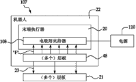
Fig. 1 is illustrating according to the functional-block diagram of the automatic laminate paving system of disclosed embodiment.
Fig. 2 is the illustrating of perspective view of the automatic laminate paving system shown in Fig. 1.
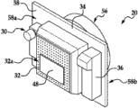
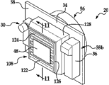
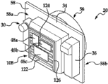
Fig. 3 is the illustrating of perspective view of end effector that forms a part for the system shown in Fig. 1 and Fig. 2.
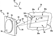
The surface that Fig. 4 shows scanning tools illustrates with the perspective view of the end effector of the feature of identification facility groove.
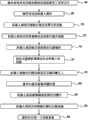
Fig. 5 is a kind of for automatically laying the illustrating of flow chart of the method for filler laminate.
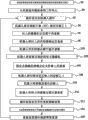
Fig. 6 is illustrates similar to Fig. 5, but shows a kind of for automatically laying the method for compound plate laminate.
Fig. 7 is for laying the illustrating of functional-block diagram of the equipment of laminate.
Fig. 8 is the illustrating of flow chart of equipment shown in a kind of Fig. 7 of the use method of laying laminate.
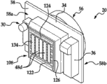
Fig. 9 is the illustrating of perspective view of end effector that forms a part for the equipment shown in Fig. 7.
Figure 10 is illustrating of the perspective view similar to Fig. 9, but shows the laminate that has been picked up and clamped by end effector.
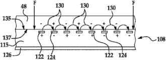
Figure 11 is illustrating along the sectional view of the line 11-11 intercepting in Figure 10.
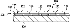
Figure 12 is the illustrating of sectional view of the alternative embodiment of electricity shown in Fig. 7 absorption clamper.
Figure 13 is illustrating of the perspective view similar with Figure 10 to Fig. 9, but shows three laminates that clamped by electromagnetic gripping device.
Figure 14 is illustrates similar to Figure 13, but shows the band that is picked up to prepare to be placed on the conducting metal on substrate by end effector.
Figure 15 is the illustrating of flow chart of Aircraft Production and maintaining method.
Figure 16 is the illustrating of block diagram of aircraft.
The specific embodiment
First with reference to Fig. 1, disclosed embodiment relates to the automatic laminate paving system of substantially being indicated by numeral 18, and it places 25 on substrate 21 by laminate 48 automatically, substrate 21 such as instrument 28 or the laminate (not shown) of placing on instrument 28 before.Laminate 48 can form a part for laminate case 24, the laminate 48 that laminate case 24 comprises the predetermined quantity with identical or different fiber orientation, described laminate is intended to be laid on instrument 28 with predefined procedure, to form features such as compound plate (not shown) or filler (not shown) on composite construction (not shown).In process of deployment, laminate 48 is placed 25 specific location on instrument 28.In an illustrated embodiment, laminate 48 is sequentially placed in 25 one or more grooves 26 in instrument.Although described the laying of composite layered plate 48 in illustrated example, but disclosed embodiment can be used to lay or place other objects, and the object particularly with the tabular or flat material form of flexibility or inflexibility, include but not limited to: plastics, pottery and metal and various forms of composite, it can be conduction or nonconducting.Therefore, term used herein " laminate " intention comprises various shapes and material.
Automatically laminate place system 18 comprises end effector 20, floor-mounted camera 42 and the controller 44 being installed on robot 22 or similar automatic control executor substantially.End effector 20 comprises scanner 36, video camera 30, holder fixed by vacuum 32 and power sensor 34.Video camera 30 is used for recording the image of the laminate 40 in case 24, and this image is processed by the image recognition software 45 of a part for formation control device 44, to sequentially identify and select 27 each laminates 48 with appropriate laying.Holder fixed by vacuum 32 can couple with vacuum system 40, and is used for clamping releasedly 29 each laminates 48, to laminate 48 is kept to 29 endways on actuator 20, until prepare to place 25 on instrument 28.Holder fixed by vacuum 32 also can be connected to the source of the gas 43 of pressurization.Source of the gas 43 can be used to normal pressure to put on laminate 48, and this can assist and discharge laminate 48 after the placement of laminate 48.End effector 20 can be equipped with the laminate clamper of other types, and this will discuss below.
In use, robot 22 moves to end effector 20 in 50, working cell, working cell 50, and pallet 30 is positioned as the laminate 48 that makes in laminate case 24 in the visual field of video camera 30.Utilize image recognition software 45, the 27 next laminates 48 that will be laid on instrument 28 are identified and selected to controller 44.In certain embodiments, the image that video camera 30 can other information of the interior reflection in writing task unit 50 (such as size and/or the shape of one or more laminate 48).In other embodiments, end effector 20 can comprise other sensor devices, such as, but not limited to RFID(radio frequency identification) reader (not shown), the selection of its sensing and laminate 48 and/or place relevant Useful Information, these information can be stored in RFID label (not shown) or other devices.
Based on laminate, select 25, end effector 20 uses the laminate 48 of holder fixed by vacuum 32 to promote and to keep the selection on 29 end effectors 20, and robot 22 moves to the position in the visual field of floor-mounted camera 42 by the laminate of selection simultaneously.Floor-mounted camera 42 is as such device, and it is for coming the position (placing and/or orientation) of the laminate 48 on recording terminal end actuator 20 by recording the image of the laminate 48 being clamped by end effector 20.The image of the laminate 48 being recorded is transported to controller 44, and this controller 44 uses the image being recorded to determine the position of the laminate 48 on end effector 20.By skew being put on to the position of the laminate 48 being recorded or utilizing other technologies, then controller 44 is converted to the position of the laminate being recorded 48 3-D spatial coordinate system 54(Fig. 2 that robot 22 uses).
Robot 22 moves to the position in the region of instrument 28 by end effector 20 from floor-mounted camera 42, conventionally towards instrument 28.Then scanner 36 on end effector 20 is used to scanning tools 28, to identify, can be used to determine that selected laminate will be placed on the feature of the position on instrument 28 (such as groove 26).In this example, the edge 26a(that scanner 36 can be used to detent 26 is referring to Fig. 4).The position of edge 26a is used for controlling the robot 22 of mobile terminal actuator 20 by controller 44, until the laminate 48 of selecting is positioned as, laminate 48 is placed on to the desired locations on instrument 28, and in illustrated example, described desired locations is corresponding to groove 26.Then end effector 20 by the groove 26 of the laminate of selecting 48 placements 25 on instrument 28, aligns with edge 26a or with other features of groove 26.End effector 20 is then to expect that big or small power compresses 31 by laminate 48 against instrument 28, and this expects that big or small power is by power sensor 34 measurements on end effector 20.Scanner 36 on end effector 20 can also be used to the regional area of preliminary examination instrument 28 before laminate is placed, and the postposition inspection of carrying out laminate 48 and/or instrument 28 after laminate 48 has been placed, to examine, the feature (such as compound plate and filler) being laid is correctly positioned on instrument 28 and/or lay features with respect to other is correctly positioned.The preliminary examination of instrument 28 can be expected, wherein changes and may in the position of some tool characteristics, occur.Such as but not limited to, due to the manufacturing tolerance of original tool and/or due to instrument doing over again or keeping in repair in its life cycle, the variation from instrument to instrument can occur in the accurate location of groove 26.Therefore, compare with nominal (appointed) position depending on as the basic groove 26 of laminate placement location, the use of the scanner 36 on end effector 20 allows the determining of actual (measurement) position of the groove 26 in particular tool 28.
As previously mentioned, by the power of being measured by power sensor 34, as feedback signal, controller 44 is controlled the size that is applied to compress the power of 31 laminates 48 by robot 22.Once laminate 48 has been placed 25 and compacted 31, holder fixed by vacuum 32 discharges laminates 48, and end effector 20 leaves from instrument 28, gets back to working cell 50, to pick up the laminate 48 of next order in case 24.Source of the gas 43 can be used to actuator endways and produce laminate 48 from the positive release (positive release) of clamper 32 before instrument 28 leaves.
Fig. 2 illustrates a typical embodiment of the automatic laminate paving system 18 shown in Fig. 1.Numeral 54 marks 3-D spatial coordinate system ,Qi Bei robot 22 and is used for promoting, transporting and laminate 48 is placed on to the desired locations place on instrument 28.Robot 22 can comprise any suitable mechanical pilot, include but not limited to conveyer belt and transporter, but in illustrated embodiment, be described to have the articulated type of articulated jib 22a, in put procedure, articulated jib 22a can assist and make laminate 48 be oriented in the position on instrument 28.Arm 22a provides rotatable wrist 22b, and end effector 20 is installed to wrist 22b.Robot 22 has from working cell 50 scopes that extend to instrument 28, according to this scope, lays laminate 48.In illustrated example, laminate case 24 comprises the array that is placed on the laminate 48 on removable pallet 30, and its la m 48 faces up and in the scope of robot 22.
Floor-mounted camera 42 is installed on the support 52 between working cell 50 and instrument 28, yet other positions of video camera 42 are possible.Because robot 22 pivotables, and end effector 20 is with 50 arc swings to instrument 28 from working cell, so the placement of video camera 42 between working cell 50 and instrument 28 allows robot 22 that laminate 48 is moved in the visual field of video camera 42.Video camera 42 can comprise any suitable imaging device of the digital picture that can produce the laminate 48 being promoted by end effector 20.In certain embodiments, the use of more than one video camera 42 can be expected.
In illustrated example, instrument 28 is described to crooked mandrel, and it has the groove 26 of a plurality of alignment in tool surfaces 28a.One or more optical reflector 55 can be placed on the surperficial 28a of instrument 28, to assisted the roughly location of end effector 20 on instrument 28 before laminate 48 is placed.Reflector 55 can be by laser scanner 36(Fig. 1) detect, however for the object of located terminal end actuator 20 roughly, other features that laser scanner 36 can sensing instrument 28, such as the edge 28b of testing tool 28.
Fig. 3 illustrates the other details of end effector 20.Laser scanner 36, holder fixed by vacuum 32 and video camera 30 are installed on a face 58a of installing plate 58.Holder fixed by vacuum 32 can comprise porous area 32a, itself and vacuum system 40(Fig. 1) couple, and be suitable for keeping laminate 48 thereon.Porous area 32a also can couple with the source of the gas 43 shown in Fig. 1, to allowed positive air pressure to put on laminate 48 at laminate 48 when clamper 32 discharges.Power sensor 34 is installed on the opposite face 58b of plate 58, and can comprise such as but not limited to piezo-electric device.The adapter 56 that is fixed to plate 58 makes end effector 20 be suitable for coupling with the wrist 22b of robot 22.
Fig. 4 illustrates on the groove 26 being roughly positioned in instrument 28 so that for laminate 48 is placed on to the end effector 20 of preparing in groove 26.In this example, groove 26 can comprise the sidewall 26a of inclination.Laser scanner 36 is used to swept notch 26a, to determine the position of this groove on instrument 28 and in 3-D spatial coordinate system 54.As previously mentioned, laser scanner 36 can be the 3-D scan type that produces the threedimensional model of groove 26, and described threedimensional model comprises sidewall 26b and the edge 26a of the inclination of groove 26.The 3-D model of the groove 26 based on being produced by laser scanner 36, controller 44(Fig. 1) can control the movement of end effector 20, to exactly laminate 48 is placed in the border of groove 26, align with the edge 26a of groove 26.
Pay close attention to now Fig. 5, it illustrates lays laminate 48(such as filler laminate) the Overall Steps of automated process.In step 64, place starts, and operator is placed on 50 places, working cell by the pallet 30 with the case 24 of laminate 48.Then,, at step 66 place, operator utilizes start the machine people circulation of controller 44.In step 68Chu, robot 22, end effector 20 is moved to the position above the pallet 30 that is positioned at 50 places, working cell.At step 70 place, the specific laminate 48 that the video camera 30 on end effector 20 selects next order in 27 casees 24 to be laid.At step 72Chu, robot 22 Mobile vacuum clampers 48, to contact with the laminate 48 of selecting, thus when robot 20 makes end effector 20 move away working cell 50 and when floor-mounted camera 42 moves, clamp 29 laminates 48, and promote laminate 48.In step 74Chu, robot 22,27 laminates 48 of selecting are presented to floor-mounted camera 42, floor-mounted camera 42 records show that laminate 48 is with respect to the image of the position of end effector 22.At step 76 place, floor-mounted camera 42 coordinates controller 44 that laminate 48 is positioned in the 3-D coordinate reference system 54 of robot 22.
In step 78Chu, robot 22, the laminate of selection 48 is moved to the position on instrument 28, and laser scanner 36 is by detection of reflected device 35 or detect the approximate location that other features (such as the edge 28b of instrument 28) are measured groove 26.Then, in step 80Chu, robot 22, move laser scanner 36 contiguous with groove 26, and scanner 36 swept notch 26 then, as discussed in conjunction with Fig. 4 before.Because the exact position of groove 26 in 3-D coordinate reference system 54 is known, shown in step 82, robot 22 then laminate 48 is accurately placed in 25 grooves 26 on instrument 28 or before be placed on the laminate 48 in groove 26.At step 84 place, power sensor 34 is used to produce feedback signal in compaction process, and this feedback signal is used for determining that by controller 40 working as laminate 48 compacted 29 puts on the size of the power of laminate 48 in instrument 28Shang Shiyou robot.Positive air pressure can be by source of the gas 43(Fig. 1) put on laminate 48, to guarantee that laminate 48 discharges from clamper 32.As illustrated at step 86 place, for each in laminate 48, step 66-84 repeats in order, until filler is done.
Fig. 6 illustrates a kind of Overall Steps of method of the automatic laying for laminate compound plate.In step 88, place starts, and composite band is laid machine or automatic fibers place machine (not shown) is placed on initial laminate on the mandrel of all instruments as shown in Figure 2 28.Secondly, at step 90 place, the case of compound plate laminate 48 is placed in working cell 50.At step 92 place, start the machine people circulation of operator, and in step 94Chu, robot 22, end effector 20 is moved on case 30.At step 96 place, the compound plate laminate 48 of next order in 27 casees 30 is located and selected to video camera 30.Step 98Chu, robot 22 then the holder fixed by vacuum 32 on mobile terminal actuator 20 to contact with compound plate laminate 48, and utilize holder fixed by vacuum 32 from case 30, to promote selected compound plate laminate 48 in step 100Chu, robot 22.In step 102Chu, robot 22, compound plate laminate 48 is presented to floor-mounted camera 42, and at step 104 place, floor-mounted camera 42 is accurately positioned at compound plate laminate 48 on the face 32a of holder fixed by vacuum 32.
In step 106Chu, robot 22, end effector 20 is moved to the position on mandrel instrument 28, and laser scanner 36 can be used to detect following feature, described feature is used to determine the accurate location that compound plate laminate 48 will be placed.Detected feature can be including but not limited to the edge (not shown) of the edge 28b of the reflector 55 on instrument 28, instrument 28 or the laminate 48 of placing before.In step 108Chu, robot 22, compound plate laminate 48 placed to 25 on tool surfaces 28a or be placed on the compound plate laminate 48 of having placed.In step 110Chu, robot 22, utilize power sensor 34 to provide feedback for controller 44, this feedback is indicated the size of the thrust that puts on compound plate laminate 48 in compaction process 29.At step 112 place, step 92-110 is repeated, until all compound plate laminates 48 have all been placed on mandrel instrument 28.At step 114 place, composite band is laid machine or automatic fibers place machine continues the process of deployment of whole laminates on compound plate laminate 48, and at step 116 place, as required or according to the indication of predetermined laminate plan, repeats the placement of compound plate laminate 48.
Pay close attention to now Fig. 7, it illustrates substantially can be for the equipment 107 of automatic landing plate paving system (all systems 54 as shown in Figure 2).Equipment 107 can be used for picking up and transport laminate 48, and placed 23 at substrate 21(such as instrument 28(Fig. 2)), on the laminate 48 or other substrate (not shown) laid before.Equipment 107 comprises end effector 20, its can by be combined before similar robot 22 of robot 22 that Fig. 1-3 describe and handle.End effector 20 comprises electricity absorption clamper 108, and it utilizes reversible Electrostatic Absorption to clamp one or more laminate 48 on end effector 20, betransported simultaneously and is placed on instrument 28.Electricity absorption clamper 108 provides power by power supply 110, and produces Electrostatic Absorption power " F ", and it is used to laminate (a plurality of laminate) 48 to be adsorbed to releasedly end effector 20.
Fig. 8 illustrates the step that the equipment 107 shown in a kind of Fig. 7 of utilization is laid the method for laminate 38 substantially.At 112 places, start, end effector 20 contacts with one or more laminate 48, all those laminates that form as shown in Figure 1 a part for the laminate case 24 on pallet 30.At step 114 place, laminate 48 is picked up and clamped to the Electrostatic Absorption power " F " that clamper 108 utilizations are adsorbed to clamper 108 by laminate.At step 116 place, end effector 20He robot 22 moves to all instruments 28 as shown in Figure 2 of substrate 21(by the laminate being held 48).At step 118 place, end effector 20 is used to the laminate 48 desired locations places of placement 23 on substrate 21.For example, end effector 20 can be placed on laminate 48 in a groove 26 of the instrument 28 shown in Fig. 2.At step 120 place, by eliminating the Electrostatic Absorption power " F " that laminate is adsorbed to clamper 108, laminate 48 discharges from end effector 20 be placed 23 in step 118 after.By closing, be supplied to the power supply of clamper 108 to eliminate Electrostatic Absorption power " F ".
As previously mentioned, equipment 107 shown in Fig. 7 and illustrated method can be for the automatic paving system 50 shown in Fig. 1 in Fig. 8, wherein video camera 30,42 is used to identify, sequentially select and pick up the laminate 48 for laying, and the orientation of determining the laminate on end effector 20 before laminate is placed.Yet, the equipment 107 shown in Fig. 7 and illustrated method can be for other automatic paving systems in Fig. 8, the end effector 20 of wherein being handled by robot 22 is used to laminate 48 to be automatically placed on substrate 21.
Fig. 9 and Figure 10 illustrate the other details of an embodiment of the equipment shown in Fig. 7.Electricity absorption clamper 108 comprises a plurality of positive and negative slender electrode pole plates that replace respectively 122,124.Electrode pad 122,124 can comprise the band of isolated substantially parallel conductive material (such as but not limited to copper or other suitable metals).Electrode pad 122,124 is staggered to be extended and is supported on backing plate 126, and backing plate 126 is installed on the extension 128 on end effector 20.Positive and negative electrode pole plate 122,124 is coupled to respectively power supply 110(Fig. 7), power supply 110 can be to orientate as with end effector 20 on same plate or from the DC power supply of plate.In illustrated example, backing plate 126 and electrode pad the 122, the 124th, substantially flat, yet it can have other geometries, comprise simple or complicated profile, this depends on laminate 48 that laminate 48 will be placed and/or the shape of instrument 28 or other substrates 21.
With reference to Figure 11, the cross section of electrode pad 122,124 is basic rectangle, yet other electrode sections geometries are possible.In illustrated embodiment, electrode pad 122,124 is embedded in pressing plate 115, and pressing plate 115 comprises the electrically non-conductive material that one deck is suitable, such as the polymer that is attached to backing plate 126.Pressing plate 115 can comprise the material of substantially rigid, can be maybe deformable a little material, and it allows the surface 135 of pressing plate 115 substantially to defer to the surface heterogeneity (not shown) of the laminate 48 being held.
When power supply is supplied to electricity absorption clamper 108, the positive and negative electrode pad replacing 122,124 is created in the electrostatic field 120 that induces static+Yu – electric charges on the surface 137 of laminate 48.On laminate 48+is contrary with the polarity of electrode pad 122,124 Yu the polarity of – electric charge, thereby causes the generation of Electrostatic Absorption power " F ", and Electrostatic Absorption power " F " attracts and thus laminate 48 is adsorbed to the surface 135 of clamper 108.Electricity absorption clamper 108 can use the power of relative a small amount of to produce relatively large Electrostatic Absorption power " F ".Such as but not limited to, power requirement can be the magnitude of approximately every newton's weight 20 microwatts.Can be supplied to the power of electrode pad 122,124 to adjust and open and close Electrostatic Absorption power " F " by control.Open-closure switching time can be for being less than the magnitude of approximately 50 milliseconds.
Figure 12 illustrates the alternative form of clamper 108, and wherein electrode pad the 122, the 124th, is directly bonded to the pole plate of non-conductive backing plate 126.Coatings 132 polymerization or other types are coated electrode pole plate 122,124 protectively.Alternately, although not shown in the accompanying drawings, electrode pad 122,124 can be surrounded by independent sealed in the protective coating of electrically non-conductive material (such as polymer) or by described protective coating.
As previously mentioned, the disclosed end effector 20 with electricity absorption clamper 108 can be used for picking up, clamp, transporting and place single laminate 48, or as illustrated at Figure 13, a plurality of laminate 48a, 48b, 48c can be picked up simultaneously, clamp and place by end effector 20.A plurality of laminate 48a, 48b, 48c each other accurate relation are arranged in pallet 40(Fig. 1 of a part that forms station 50 in advance) upper or other surperficial on.Compare with next an automatic or manual laying put procedure, when being clamped simultaneously and picking up by electricity absorption clamper, laminate 48a, 48b, 48c keep its relation of arranging in advance, and it is placed and be pressed on instrument 28 or other substrates 21 by end effector 20 as the group of arranging in advance simultaneously.
Figure 14 illustrates the band 134 that makes electricity consumption absorption clamper 108 pick up and clamp a plurality of thin metal foils, described band 134 can by end effector 20 separately or as one group, be placed on substrate 21(such as aircraft wing (not shown)) on.Alternately, the holder fixed by vacuum 32(Fig. 1 before describing) can be used on end effector 20, to pick up and to clamp metal forming band 134.Yet, in some applications, by metal mesh opening (not shown) plate is applied to aircraft skin (not shown) implements lightning Protection in the situation that, can preferably on actuator 20, use electrostatic clamp device 108 endways.
Embodiment of the present disclosure can be applied to various potential application, is especially applied in carrier, comprises for example Aero-Space, boats and ships, automobile application and other application that can use automatic installation apparatus.Therefore, referring now to Figure 15 and Figure 16, embodiment of the present disclosure can the background for aircraft manufacturing shown in Figure 15 and maintaining method 136 and aircraft 138 shown in Figure 16 in.Only lift several examples, the aircraft application of the disclosed embodiments can comprise such as but not limited to: the laying of stiffener (such as fuselage skin, wing cover, chain of command, hatch, floor panel, door-plate, cover plate and empennage), the laying of tack coat and for the laying of the thin plate of the metal forming of the application of being struck by lightning.At pre-production period, illustrative methods 108 can comprise the specification and design 140 and material purchases 142 of aircraft 138.At production period, carry out assembly and subassembly manufacture 144 and the system combination 146 of aircraft 138.Thereafter, aircraft 138 can experience authentication and pay 148, to make it come into operation 150.When being used by client, aircraft 138 be arranged to carry out daily maintenance with safeguard 152(its can also comprise improvement, reconfigure, renovation etc.).
Can for example, by each processing in system integrator, third party and/or operator (, client) execution or implementation method 108.For the object of this description, system integrator can include but not limited to planemaker and the main system subcontractor of any amount; Third party can include but not limited to distributors, subcontractor and the supplier of any amount; And operator can be airline, leasing company, military entity, service organization etc.
As shown in Figure 16, the aircraft 138 of producing by illustrative methods 136 can comprise fuselage 154 and a plurality of system 156 and internal structure 158.The example of AS 156 comprises one or more in propulsion system 160, electrical system 162, hydraulic system 164 and environmental system 166.Other system that can comprise any amount.Although show aviation example, principle of the present disclosure can be applied to other industry, such as boats and ships and auto industry.
The system and method presenting in this article can be used during any one or the more stage of producing with maintaining method 136.For example, corresponding to the assembly of production process 144 or subassembly, can be similar to assembly that aircraft 110 produces in use time or the mode of subassembly is produced or manufactures.Equally, for example, by fully accelerating the assembling of aircraft 138 or the cost of reduction aircraft 138, can during production phase 144 and 146, utilize one or more apparatus embodiments, embodiment of the method or its combination.Similarly, at aircraft 138, in use time, one or more apparatus embodiments, embodiment of the method or its combination can be such as but not limited to being used to maintenance and safeguarding 152.
Although described embodiment of the present disclosure about some exemplary embodiment, should be understood that specific embodiment is for illustrating unrestriced object, because those skilled in the art will envision that other variants.
Claims (15)
1. for composite layered plate being laid on to a system for preselected position, described system comprises:
Robot;
End effector in described robot, it is for promoting laminate and described laminate being placed on to preselected position;
For recording the device of the position of the described laminate on described end effector; And
With the controller of position recording device coupling, this controller is used for controlling described robot and described end effector so that described laminate is placed on to described position.
2. system according to claim 1, wherein said end effector comprises for clamping the clamper of the vacuumizing of described laminate.
3. according to claim 1 or system claimed in claim 2, wherein said end effector comprises for clamping the electricity absorption clamper of described laminate.
4. according to the system described in aforementioned arbitrary claim, wherein said electricity absorption clamper comprises one group of electrode pad, this electrode pad be suitable for for induce the Electric source coupling of electrostatic charge on described laminate.
5. according to the system described in aforementioned arbitrary claim, wherein said position recording device comprises floor-mounted camera, and described floor-mounted camera is for the described laminate on end effector described in imaging.
6. according to the system described in aforementioned arbitrary claim, it also comprises:
The video camera being coupled with described controller on described end effector, it observed described laminate before being promoted by described end effector at laminate, and
Wherein said controller comprises for identify and select the software of described laminate from a plurality of laminates.
7. according to the system described in aforementioned arbitrary claim, it also comprises:
Detector on described end effector, described detector is for detection of the relevant feature in the position that will be placed with described laminate.
8. according to the system described in aforementioned arbitrary claim, wherein said characteristic position detection means is laser scanner.
9. according to the system described in aforementioned arbitrary claim, wherein, when described laminate is placed on described instrument, described end effector and described robot are applied to described laminate by thrust, and described system also comprises:
Sensor on described end effector, it is for the size of thrust described in sensing.
10. laminate is laid on to the method in the precalculated position on substrate, the method comprises:
Pick up laminate;
Described laminate is moved to the region in the precalculated position that contiguous described laminate will be placed;
The described precalculated position orientation that described laminate will be placed with respect to described laminate; And
The described laminate being oriented is placed on to the described pre-position on described substrate.
11. methods according to claim 10, wherein utilize Electrostatic Absorption power to clamp described laminate, thereby carry out picking up of described laminate.
12. methods according to claim 10, wherein:
By clamp described laminate with end effector, carry out picking up of described laminate,
By described end effector being moved to the described region in contiguous described precalculated position, carry out the movement of described laminate, and
Utilize described end effector to carry out the placement of described laminate.
13. methods according to claim 12, it also comprises:
The relevant feature in position of utilizing described end effector to detect will to be placed with described laminate,
Wherein utilizing described end effector to place described laminate is described feature based on detected, and utilizes the robotic manipulator of automatically controlling to carry out the described region that described end effector is moved to contiguous described precalculated position.
14. methods according to claim 12, it also comprises:
Utilize described end effector that described laminate is compressed against described substrate; And
Utilize the sensor on described end effector to come sensing by described end effector, to be applied to the described thrust of described laminate.
15. methods according to claim 12, it also comprises:
Utilize described end effector identify will be picked and mobile laminate.
Applications Claiming Priority (3)
| Application Number | Priority Date | Filing Date | Title |
|---|---|---|---|
| US13/166,306 US9969131B2 (en) | 2011-06-22 | 2011-06-22 | Automated ply layup system |
| US13/166,306 | 2011-06-22 | ||
| PCT/US2012/038139 WO2012177340A1 (en) | 2011-06-22 | 2012-05-16 | Automated ply layup system and method of laying up |
Publications (1)
| Publication Number | Publication Date |
|---|---|
| CN103619567A true CN103619567A (en) | 2014-03-05 |
Family
ID=46178807
Family Applications (1)
| Application Number | Title | Priority Date | Filing Date |
|---|---|---|---|
| CN201280030394.4A Pending CN103619567A (en) | 2011-06-22 | 2012-05-16 | Automated ply layup system and method of laying up |
Country Status (9)
| Country | Link |
|---|---|
| US (1) | US9969131B2 (en) |
| EP (1) | EP2723553B1 (en) |
| JP (1) | JP6095655B2 (en) |
| KR (1) | KR101958032B1 (en) |
| CN (1) | CN103619567A (en) |
| CA (1) | CA2832229C (en) |
| ES (1) | ES2784153T3 (en) |
| PT (1) | PT2723553T (en) |
| WO (1) | WO2012177340A1 (en) |
Cited By (12)
| Publication number | Priority date | Publication date | Assignee | Title |
|---|---|---|---|---|
| CN104570955A (en) * | 2014-11-24 | 2015-04-29 | 中国科学院自动化研究所 | Control system and method of automatic tow spreading machine for composite material |
| CN105234943A (en) * | 2015-09-09 | 2016-01-13 | 大族激光科技产业集团股份有限公司 | Industrial robot demonstration device and method based on visual recognition |
| CN106927062A (en) * | 2015-12-29 | 2017-07-07 | 波音公司 | Coordinated composite band laying |
| CN108340593A (en) * | 2017-01-23 | 2018-07-31 | 波音公司 | The system and method for being used to form composite part |
| CN108453777A (en) * | 2017-01-31 | 2018-08-28 | 兄弟工业株式会社 | Object holder |
| CN108778638A (en) * | 2016-01-12 | 2018-11-09 | 格拉比特公司 | The method and system of operation based on negative pressure and electric adhesive composition in manufacture |
| CN109421292A (en) * | 2017-08-31 | 2019-03-05 | 波音公司 | Gyratory compaction tool |
| CN110621598A (en) * | 2017-05-19 | 2019-12-27 | 豪迈面板分割科技有限公司 | Handling device for at least partially planar loads and method for operating a handling device |
| CN111565919A (en) * | 2017-10-20 | 2020-08-21 | 迈凯轮汽车有限公司 | Composite fabrication |
| CN108630591B (en) * | 2017-03-15 | 2020-12-29 | 启端光电股份有限公司 | Micro-component transfer system |
| CN113899333A (en) * | 2021-09-29 | 2022-01-07 | 苏州佳祺仕信息科技有限公司 | Distance measuring method and device, electronic equipment and storage medium |
| CN115485108A (en) * | 2020-03-06 | 2022-12-16 | 斯凯普技术有限公司 | Method for operating a pick-up robot and related apparatus |
Families Citing this family (63)
| Publication number | Priority date | Publication date | Assignee | Title |
|---|---|---|---|---|
| US8826957B2 (en) * | 2012-08-31 | 2014-09-09 | General Electric Company | Methods and systems for automated ply layup for composites |
| DE102012019841B4 (en) * | 2012-10-09 | 2022-01-05 | Grenzebach Maschinenbau Gmbh | Method and device for moving large, extremely oversized panels |
| DE102012019839B4 (en) * | 2012-10-09 | 2017-08-24 | Grenzebach Maschinenbau Gmbh | Method and device for the transport of large-size plates in extreme oversize |
| US9162436B2 (en) * | 2013-01-04 | 2015-10-20 | The Boeing Company | Method and apparatus for accurate registration of composite laminates |
| WO2014140146A1 (en) * | 2013-03-12 | 2014-09-18 | Dieffenbacher GmbH Maschinen- und Anlagenbau | Method and systems for producing advanced composite components |
| DE102013104609B4 (en) * | 2013-05-06 | 2016-10-20 | Deutsches Zentrum für Luft- und Raumfahrt e.V. | Nestingablage |
| CN103659796A (en) * | 2013-06-21 | 2014-03-26 | 成都万先自动化科技有限责任公司 | Intelligent carrying stacking and positioning robot |
| KR20150018696A (en) | 2013-08-08 | 2015-02-24 | 주식회사 케이티 | Method, relay apparatus and user terminal for renting surveillance camera |
| KR20150018037A (en) * | 2013-08-08 | 2015-02-23 | 주식회사 케이티 | System for monitoring and method for monitoring using the same |
| AT514721B1 (en) * | 2013-08-30 | 2015-06-15 | Engel Austria Gmbh | Shaping plant for producing a fiber-plastic composite |
| WO2015094375A1 (en) * | 2013-12-20 | 2015-06-25 | Grabit, Inc. | Modular electroadhesive gripping system |
| CN106163745A (en) * | 2013-12-20 | 2016-11-23 | 格拉比特公司 | Modular electrical adheres to grasping system |
| KR20150075224A (en) | 2013-12-24 | 2015-07-03 | 주식회사 케이티 | Apparatus and method for providing of control service |
| US10343857B2 (en) | 2014-01-22 | 2019-07-09 | Symbiotic Canada ULC. | Vision-assisted robotized depalletizer |
| JP2017511262A (en) * | 2014-03-17 | 2017-04-20 | グラビット,インク. | Electric adhesion gripping system with smart brake and measurement |
| WO2015164264A1 (en) | 2014-04-21 | 2015-10-29 | Grabit, Inc. | Automated item handling with reconfigurable totes |
| US20150338213A1 (en) * | 2014-05-20 | 2015-11-26 | Par Systems, Inc. | Adaptive Manufacturing System |
| JP6372195B2 (en) * | 2014-06-30 | 2018-08-15 | 東レ株式会社 | Preform manufacturing method and fiber reinforced plastic manufacturing method |
| US9873230B1 (en) | 2014-08-19 | 2018-01-23 | The Boeing Company | Mobile system for automated layup and compaction of composite laminates |
| EP3198221A1 (en) | 2014-09-24 | 2017-08-02 | Bombardier Inc. | Laser vision inspection system and method |
| DE102015201551A1 (en) * | 2015-01-29 | 2016-08-04 | Bayerische Motoren Werke Aktiengesellschaft | Recognition device for detecting alignment of blanks of semifinished products |
| US10076883B2 (en) * | 2015-05-05 | 2018-09-18 | The Boeing Company | System and method for manufacturing off-axis prepreg material |
| US9618459B2 (en) | 2015-05-18 | 2017-04-11 | Flightware, Inc. | Systems and methods for automated composite layup quality assurance |
| US10668673B2 (en) | 2015-05-18 | 2020-06-02 | Flightware, Inc. | Systems and methods for automated composite layup quality assurance |
| US10016947B2 (en) * | 2015-05-21 | 2018-07-10 | The Boeing Company | High rate production fiber placement system and method |
| DE102015009177A1 (en) * | 2015-07-09 | 2017-01-12 | Broetje-Automation Gmbh | Method for producing a fiber-metal laminate component of an aircraft |
| CN105032836A (en) * | 2015-08-23 | 2015-11-11 | 华东交通大学 | Mechanical arm type automatic piece insertion device |
| JP6762212B2 (en) * | 2015-12-28 | 2020-09-30 | 帝人株式会社 | Manufacturing method of molded product |
| DE102016003816B4 (en) * | 2016-03-26 | 2019-05-29 | Audi Ag | Industrial robot with a monitoring space carried by the manipulator |
| JP6665040B2 (en) * | 2016-06-20 | 2020-03-13 | 三菱重工業株式会社 | Robot control system and robot control method |
| GB2552981B (en) * | 2016-08-17 | 2020-04-01 | Univ Of Hertfordshire Higher Education Corporation | An Interactive Humanoid Robot using RFID Tagged Objects |
| US10781056B2 (en) | 2016-12-22 | 2020-09-22 | General Electric Company | Adaptive apparatus and system for automated handling of components |
| US10773902B2 (en) | 2016-12-22 | 2020-09-15 | General Electric Company | Adaptive apparatus and system for automated handling of components |
| US20180264660A1 (en) * | 2017-03-20 | 2018-09-20 | Kindred Systems Inc. | Systems, devices, articles, and methods for prehension |
| US10160169B1 (en) | 2017-06-26 | 2018-12-25 | General Electric Company | Systems and methods of forming a composite layup structure |
| US10195747B1 (en) | 2017-08-03 | 2019-02-05 | General Electric Company | Multi-faced apparatus and system for automated handling of components |
| EP3477806B1 (en) * | 2017-10-30 | 2022-03-02 | Komax Holding Ag | Method for connecting a first cable with a second cable, cable assembly and cable connecting apparatus for connecting a first cable with a second cable |
| CN108081312A (en) * | 2017-11-03 | 2018-05-29 | 上海工程技术大学 | A kind of robot mechanical arm centering calibration system for being used to capture miniature parts |
| AT520587B1 (en) * | 2017-11-14 | 2021-03-15 | Engel Austria Gmbh | Method for arranging semi-finished products |
| US10843449B2 (en) | 2017-12-14 | 2020-11-24 | The Boeing Company | Method and apparatus for forming composite plies on contoured tool surfaces |
| US10899089B2 (en) | 2018-03-30 | 2021-01-26 | The Boeing Company | Automated fiber placement end effector with laminar gas cooling jet and infrared image processor for in-situ inspection |
| US10926490B2 (en) * | 2018-04-09 | 2021-02-23 | The Boeing Company | Composite laminate forming apparatus and method therefor |
| US10695916B2 (en) * | 2018-07-05 | 2020-06-30 | The Boeing Company | End effectors having reconfigurable vacuum heads |
| US11007635B2 (en) | 2018-07-25 | 2021-05-18 | The Boeing Company | Gravity compensation for self-propelled robotic vehicles crawling on non-level surfaces |
| WO2020033484A1 (en) * | 2018-08-07 | 2020-02-13 | University Of Southern California | Hybrid formation of multi-layer prepreg composite sheet layup |
| CN113329865B (en) | 2018-10-15 | 2023-12-29 | 通用电气公司 | System and method for automated film removal |
| US11305498B2 (en) * | 2018-12-21 | 2022-04-19 | The Boeing Company | System and method for fabricating a composite ply layup |
| US11318689B2 (en) | 2018-12-21 | 2022-05-03 | The Boeing Company | Ply transporting and compacting apparatus and method therefor |
| JP7161399B2 (en) * | 2018-12-28 | 2022-10-26 | 株式会社Subaru | Resin impregnation measuring device |
| US11198260B2 (en) | 2019-03-04 | 2021-12-14 | The Boeing Company | Thermographic inspection for tape layup machines |
| US11141814B2 (en) | 2019-03-04 | 2021-10-12 | The Boeing Company | Thermographic inspection for tape layup machines |
| US11040500B2 (en) | 2019-03-04 | 2021-06-22 | The Boeing Company | Thermographic inspection for tape layup machines |
| US11192665B2 (en) | 2019-03-04 | 2021-12-07 | The Boeing Company | Thermographic inspection of lanes of tape laid-up by tape layup machines, based on acquired thermographic images |
| CN110065288A (en) * | 2019-04-02 | 2019-07-30 | 深圳市联得自动化装备股份有限公司 | Abutted equipment and applying method |
| GB201908127D0 (en) * | 2019-06-07 | 2019-07-24 | Renishaw Plc | Manufacturing method and apparatus |
| NL2023372B1 (en) | 2019-06-25 | 2021-02-01 | Airborne Int B V | Preforming system and method |
| NL2023504B1 (en) * | 2019-07-15 | 2021-02-08 | Airborne Int B V | Apparatus and method for processing consolidated stacks of fiber reinforced plies |
| FR3101569B1 (en) * | 2019-10-08 | 2021-09-10 | Safran Nacelles | Automatic lay-up and compaction machine |
| US11351678B1 (en) * | 2020-03-10 | 2022-06-07 | Amazon Technologies, Inc. | Dynamically adjustable suction cups |
| US11472139B2 (en) | 2020-05-15 | 2022-10-18 | The Boeing Company | Automated composite fabrication systems and methods |
| KR102426189B1 (en) * | 2020-12-22 | 2022-07-28 | 주식회사 대덕알앤디 | Smart EOAT robot system |
| US12066819B2 (en) | 2021-10-13 | 2024-08-20 | The Boeing Company | Printed fiducial system for accurate pick and place |
| US11951697B2 (en) | 2021-12-12 | 2024-04-09 | The Boeing Company | Scalable area gripper, system, and method for a material handling process for composite manufacturing |
Citations (1)
| Publication number | Priority date | Publication date | Assignee | Title |
|---|---|---|---|---|
| US20100007065A1 (en) * | 2008-07-11 | 2010-01-14 | Raphael Reinhold | Device for use in the manufacture of fiber-reinforced components |
Family Cites Families (24)
| Publication number | Priority date | Publication date | Assignee | Title |
|---|---|---|---|---|
| JPS62104740A (en) | 1985-11-01 | 1987-05-15 | Hitachi Ltd | Layer building device of multilayer printed circuit board |
| US5876550A (en) | 1988-10-05 | 1999-03-02 | Helisys, Inc. | Laminated object manufacturing apparatus and method |
| US5183670A (en) | 1991-04-30 | 1993-02-02 | United Technologies Corporation | Bi-functional transfer foot |
| US5209804A (en) | 1991-04-30 | 1993-05-11 | United Technologies Corporation | Integrated, automted composite material manufacturing system for pre-cure processing of preimpregnated composite materials |
| US6131973A (en) | 1998-10-01 | 2000-10-17 | Sikorsky Aircraft Corporation | Vacuum transfer device |
| US7930061B2 (en) * | 2002-08-31 | 2011-04-19 | Applied Materials, Inc. | Methods and apparatus for loading and unloading substrate carriers on moving conveyors using feedback |
| AU2003270696A1 (en) * | 2002-09-12 | 2004-05-04 | David Groppe | Precision feed end-effector composite fabric tape-laying apparatus and method |
| JP4174342B2 (en) * | 2003-02-19 | 2008-10-29 | ファナック株式会社 | Work transfer device |
| US7341086B2 (en) * | 2004-10-29 | 2008-03-11 | The Boeing Company | Automated fabric layup system and method |
| US8601694B2 (en) | 2008-06-13 | 2013-12-10 | The Boeing Company | Method for forming and installing stringers |
| US7766063B2 (en) * | 2005-04-28 | 2010-08-03 | The Boeing Company | Machine assisted laminator and method |
| US20070277919A1 (en) | 2006-05-16 | 2007-12-06 | The Boeing Company | Systems and methods for monitoring automated composite manufacturing processes |
| US8050486B2 (en) | 2006-05-16 | 2011-11-01 | The Boeing Company | System and method for identifying a feature of a workpiece |
| US7551419B2 (en) * | 2006-06-05 | 2009-06-23 | Sri International | Electroadhesion |
| DE202007006528U1 (en) | 2007-05-04 | 2008-09-18 | Kuka Systems Gmbh | Device for handling pieces of material |
| JP2008310724A (en) * | 2007-06-18 | 2008-12-25 | Nippon Telegr & Teleph Corp <Ntt> | Three-dimensional shape restoration device, three-dimensional shape restoration method, three-dimensional shape restoration program and recording medium with its program stored |
| US8936695B2 (en) | 2007-07-28 | 2015-01-20 | The Boeing Company | Method for forming and applying composite layups having complex geometries |
| DE102007061431B4 (en) | 2007-12-20 | 2013-08-08 | Airbus Operations Gmbh | Method for stiffening a fiber composite component and vacuum mat and arrangement for producing a stiffened fiber composite component |
| JP2009148858A (en) | 2007-12-21 | 2009-07-09 | Pioneer Electronic Corp | Device for disposing electronic component |
| US9694546B2 (en) * | 2008-02-12 | 2017-07-04 | The Boeing Company | Automated fiber placement compensation |
| JP4475339B2 (en) | 2008-02-26 | 2010-06-09 | トヨタ自動車株式会社 | Power assist device and control method thereof |
| US20100063304A1 (en) * | 2008-09-09 | 2010-03-11 | Basf Se | Apparatus for automatic catalyst exchange in a reactor with a bundle of catalyst tubes |
| US8599531B2 (en) | 2009-01-11 | 2013-12-03 | Applied Materials, Inc. | Electrostatic end effector apparatus, systems and methods |
| DE102010044721A1 (en) | 2010-09-08 | 2012-03-08 | Daimler Ag | Method and device for producing a semi-finished fiber product |
-
2011
- 2011-06-22 US US13/166,306 patent/US9969131B2/en not_active Expired - Fee Related
-
2012
- 2012-05-16 CA CA2832229A patent/CA2832229C/en not_active Expired - Fee Related
- 2012-05-16 WO PCT/US2012/038139 patent/WO2012177340A1/en unknown
- 2012-05-16 EP EP12724465.5A patent/EP2723553B1/en active Active
- 2012-05-16 KR KR1020137026689A patent/KR101958032B1/en active IP Right Grant
- 2012-05-16 PT PT127244655T patent/PT2723553T/en unknown
- 2012-05-16 JP JP2014516972A patent/JP6095655B2/en not_active Expired - Fee Related
- 2012-05-16 CN CN201280030394.4A patent/CN103619567A/en active Pending
- 2012-05-16 ES ES12724465T patent/ES2784153T3/en active Active
Patent Citations (1)
| Publication number | Priority date | Publication date | Assignee | Title |
|---|---|---|---|---|
| US20100007065A1 (en) * | 2008-07-11 | 2010-01-14 | Raphael Reinhold | Device for use in the manufacture of fiber-reinforced components |
Cited By (19)
| Publication number | Priority date | Publication date | Assignee | Title |
|---|---|---|---|---|
| CN104570955B (en) * | 2014-11-24 | 2018-06-22 | 中国科学院自动化研究所 | A kind of composite material automatic fiber placement machine control system and control method |
| CN104570955A (en) * | 2014-11-24 | 2015-04-29 | 中国科学院自动化研究所 | Control system and method of automatic tow spreading machine for composite material |
| CN105234943A (en) * | 2015-09-09 | 2016-01-13 | 大族激光科技产业集团股份有限公司 | Industrial robot demonstration device and method based on visual recognition |
| CN105234943B (en) * | 2015-09-09 | 2018-08-14 | 大族激光科技产业集团股份有限公司 | A kind of industrial robot teaching device and method of view-based access control model identification |
| CN106927062A (en) * | 2015-12-29 | 2017-07-07 | 波音公司 | Coordinated composite band laying |
| CN106927062B (en) * | 2015-12-29 | 2021-11-23 | 波音公司 | Coordinated composite tape laying |
| CN108778638A (en) * | 2016-01-12 | 2018-11-09 | 格拉比特公司 | The method and system of operation based on negative pressure and electric adhesive composition in manufacture |
| CN108340593B (en) * | 2017-01-23 | 2021-08-06 | 波音公司 | System and method for forming composite parts |
| CN108340593A (en) * | 2017-01-23 | 2018-07-31 | 波音公司 | The system and method for being used to form composite part |
| CN108453777A (en) * | 2017-01-31 | 2018-08-28 | 兄弟工业株式会社 | Object holder |
| CN108630591B (en) * | 2017-03-15 | 2020-12-29 | 启端光电股份有限公司 | Micro-component transfer system |
| CN110621598A (en) * | 2017-05-19 | 2019-12-27 | 豪迈面板分割科技有限公司 | Handling device for at least partially planar loads and method for operating a handling device |
| CN109421292A (en) * | 2017-08-31 | 2019-03-05 | 波音公司 | Gyratory compaction tool |
| US11135785B2 (en) | 2017-08-31 | 2021-10-05 | The Boeing Company | Rotary compaction tool |
| CN109421292B (en) * | 2017-08-31 | 2022-01-04 | 波音公司 | Rotary compaction tool |
| CN111565919A (en) * | 2017-10-20 | 2020-08-21 | 迈凯轮汽车有限公司 | Composite fabrication |
| US11478956B2 (en) | 2017-10-20 | 2022-10-25 | Mclaren Automotive Limited | Composite manufacturing |
| CN115485108A (en) * | 2020-03-06 | 2022-12-16 | 斯凯普技术有限公司 | Method for operating a pick-up robot and related apparatus |
| CN113899333A (en) * | 2021-09-29 | 2022-01-07 | 苏州佳祺仕信息科技有限公司 | Distance measuring method and device, electronic equipment and storage medium |
Also Published As
| Publication number | Publication date |
|---|---|
| CA2832229A1 (en) | 2012-12-27 |
| WO2012177340A1 (en) | 2012-12-27 |
| US9969131B2 (en) | 2018-05-15 |
| EP2723553B1 (en) | 2020-02-19 |
| KR101958032B1 (en) | 2019-03-13 |
| JP2014522747A (en) | 2014-09-08 |
| ES2784153T3 (en) | 2020-09-22 |
| JP6095655B2 (en) | 2017-03-15 |
| KR20140033351A (en) | 2014-03-18 |
| EP2723553A1 (en) | 2014-04-30 |
| US20120330453A1 (en) | 2012-12-27 |
| WO2012177340A9 (en) | 2013-02-14 |
| CA2832229C (en) | 2016-11-22 |
| PT2723553T (en) | 2020-03-27 |
Similar Documents
| Publication | Publication Date | Title |
|---|---|---|
| CN103619567A (en) | Automated ply layup system and method of laying up | |
| US10137544B2 (en) | Method of assembling components | |
| JP5809837B2 (en) | Method and apparatus for forming and applying composite laminates having complex geometries | |
| EP3733387A1 (en) | Stiffener composite charge application system | |
| EP3406430B1 (en) | Pick and place end effector | |
| JP2011251525A5 (en) | ||
| CN101415323B (en) | Vision inspection apparatus and plate-establishing inspection device and method therefore | |
| EP2385340A1 (en) | Automatic system for quality control and position correction of taped parts | |
| US9314976B2 (en) | Systems and methods for compacting a charge of composite material | |
| US10173371B1 (en) | System and method for forming a bonded joint | |
| US10926490B2 (en) | Composite laminate forming apparatus and method therefor | |
| JP2016510268A (en) | Method for accurate alignment of composite laminates | |
| EP3132238B1 (en) | Optical scanner and projection apparatus for thermal management of composite repairs and method of thermal management | |
| US8324911B2 (en) | Gap mapping for fitting composite doublers | |
| JP2020114665A (en) | System and method for fabricating composite ply layup | |
| CN111347752B (en) | Laminate conveying and compacting apparatus and method | |
| CN105526220A (en) | Automatic sponge adhesion unit for sheet metal parts of evaporators and condensers of air conditioners and use method thereof | |
| EP3323602A1 (en) | Method and tool system for manufacturing a multilayer fibre structure | |
| EP4000888B1 (en) | Continuously moving line for making composite laminate parts | |
| US20240123631A1 (en) | Pick-and-place manufacturing system and method | |
| US20230113580A1 (en) | Printed fiducial system for accurate pick and place | |
| US20240227326A1 (en) | Composite Compaction System Supported by a Number of Morphable Bag Supports | |
| US20220153433A1 (en) | Methods and Systems for Assembling a Structure | |
| EP3023231A1 (en) | Systems and methods for compacting a charge of composite material |
Legal Events
| Date | Code | Title | Description |
|---|---|---|---|
| PB01 | Publication | ||
| PB01 | Publication | ||
| C10 | Entry into substantive examination | ||
| SE01 | Entry into force of request for substantive examination | ||
| RJ01 | Rejection of invention patent application after publication | ||
| RJ01 | Rejection of invention patent application after publication |
Application publication date: 20140305 |