CN103541655A - Drill rod buffer positioning device of hydraulic rock drill - Google Patents
Drill rod buffer positioning device of hydraulic rock drill Download PDFInfo
- Publication number
- CN103541655A CN103541655A CN201310505065.7A CN201310505065A CN103541655A CN 103541655 A CN103541655 A CN 103541655A CN 201310505065 A CN201310505065 A CN 201310505065A CN 103541655 A CN103541655 A CN 103541655A
- Authority
- CN
- China
- Prior art keywords
- drill rod
- bit shank
- drill steel
- drill
- buffer
- Prior art date
- Legal status (The legal status is an assumption and is not a legal conclusion. Google has not performed a legal analysis and makes no representation as to the accuracy of the status listed.)
- Granted
Links
Images
Landscapes
- Earth Drilling (AREA)
- Percussive Tools And Related Accessories (AREA)
Abstract
The invention relates to a drill rod buffer positioning device of a hydraulic rock drill. The drill rod buffer positioning device comprises a nose body of the rock drill and a drill rod tail sleeve mounted in the nose body and is characterized by further comprising an upper connecting plate, a buffer body and a lower connecting plate which are sequentially connected. The upper connecting plate is connected with a nose body flange. A through drill rod tail cavity is coaxially formed in the buffer body and the upper connecting plate. A drill rod tail cavity, a shoulder and a drill rod cavity are coaxially arranged on the lower connecting plate. An upward drill rod tail insertion groove is formed on the same side of each of the upper connecting plate, the buffer body and the lower connecting plate. The drill rod buffer positioning device has the advantages that rebound impact generated on a drill rod is absorbed by the buffer body, rigid impact among parts is avoided, and service lives of the drill rod and a machine body are prolonged; the shoulder axially limits a drill rod tail, and drill rod holding is unnecessary when the drill rod is vertical; the drill rod buffer positioning device is simple in structure, reasonable in design and simple to use.
Description
Technical field
The present invention relates to a kind of for impacting the drive unit creeping into rotary joint, especially a kind of drill steel buffering locator of hydraulic gate.
Background technology
Hydraulic gate is a kind of rock drill occurring in recent years, take and circulates hydraulic oil as power, drives drill steel, bore bit, the machinery of punchinging in rock mass in impact rotating mode.It compare with air drill there is consuming little energy, that cutting rate is fast, efficiency is high, noise is little, be easy to control, lock of tool drilling is few, drill tool life is long etc. is a little many, obtaining and developing rapidly in recent years.
Hydraulic gate is mainly comprised of beater mechanism and slew gear two large divisions.Beater mechanism is comprised of critical pieces such as cylinder body, piston, reversal valve, accumulators, and entering in cylinder body controlled in the commutation by reversal valve, high-frequency reciprocating that oil return realizes piston moves, and constantly impacts drill steel tail end, realizes bore bit impact drilling; Slew gear is comprised of hydraulic motor, reduction gearing etc., and piston is when backstroke, and fluid motor-driven reduction gearing drives drill steel revolution certain angle.So go round and begin again, carry out rock drilling boring.The hexahedron structure adopting due to the afterbody of drill steel is coincide and is arranged in the bit shank sleeve in handpiece body, both belong to rigid connection, after piston impact drill steel tail end, the impact stress ripple not absorbed by rock, a part is returned by drill steel, with shock wave form, by bit shank sleeve, acts on handpiece body, between the parts in bit shank sleeve and handpiece body, causes high vibration, make parts produce gouging abrasion, affect the application life of hammer drill.In addition, shaftless to locating part between the afterbody of drill steel and the bit shank sleeve in handpiece body, when cutter bores upright opening, in the drill steel lifting process after the in place and boring of drill steel, need manually to control drill steel, exist and use inconvenient deficiency.
Summary of the invention
Shaftless existing to locating part used inconvenient deficiency in order to overcome in prior art that the rigid connection of drill steel and bit shank sleeve easily causes high vibration between the parts in bit shank sleeve and handpiece body and between wearing and tearing and drill steel and bit shank sleeve, the invention provides a kind of simple in structure, reasonable in design, easy to use, change the pricker drill steel buffer of hydraulic gate efficiently.
The technical scheme that technical solution problem of the present invention adopts is: a kind of drill steel buffer of hydraulic gate, it comprises the handpiece body of hammer drill, be arranged in handpiece body for the bit shank sleeve of drill steel is installed, described bit shank sleeve intracavity section is the hexahedron matching with drill steel afterbody, it is characterized in that: it also comprises tie-plate on, one buffer body and once tie-plate, the upper end of described upper tie-plate connects with the end flange at handpiece body, one end of the lower end of upper tie-plate and described buffer body is fixedly connected, the described upper end of lower link dish and the other end of buffer body are fixedly connected, at described upper tie-plate, on buffer body, corresponding bit shank sleeve coaxially has respectively the bit shank chamber of running through, on described lower link dish, coaxially have successively bit shank chamber and drill steel chamber, between the bit shank chamber of lower link dish and drill steel chamber, be provided with shoulder, the bit shank axial limiting of this shoulder to drill steel, at upper tie-plate, the homonymy of buffer body and lower link dish upwards respectively correspondence have bit shank insertion groove.
The present invention is owing to being provided with joining upper tie-plate, buffer body and lower link dish successively, upper tie-plate and handpiece body flange connect, on upper tie-plate, buffer body, coaxially have the bit shank chamber of running through, on lower link dish, coaxially have successively bit shank chamber and drill steel chamber, between bit shank chamber and drill steel chamber, be provided with the shoulder to bit shank axial limiting, at the homonymy of upper tie-plate, buffer body and lower link dish, upwards have bit shank insertion groove.The present invention after the bit shank insertion groove insertion with side direction, coordinates the bit shank of drill steel with installation with the bit shank sleeve in handpiece body through upper tie-plate, buffer body and lower link dish, and its drill steel changes the outfit fast; The rebounce energy producing during drill steel rock drilling boring is absorbed by buffer body, prevents that drill steel bounce-back from driving associated components and body to form rigid impact, improves the application life of drill steel and body; When cutter bores upright opening, in the drill steel lifting process after the in place and boring of drill steel, by the bit shank chamber of lower link dish and the shoulder between drill steel chamber, bit shank is carried out to axial limiting, do not need manually to control drill steel.Compared with prior art, the present invention has advantages of simple in structure, reasonable in design, easy to use.
Accompanying drawing explanation
Below in conjunction with drawings and Examples, the present invention will be further described.
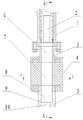
Fig. 1 is the main sectional view of a kind of structure of the present invention;
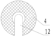
Fig. 2 is the sectional view along A-A line in Fig. 1;
Fig. 3 is the sectional view along B-B line in Fig. 1.
In figure: 1. handpiece body, 2. bit shank sleeve, 3. goes up tie-plate, 4. buffer body, 5. lower link dish, 6. goes up tie-plate bit shank chamber, 7. buffer body bit shank chamber, 8. lower link dish bit shank chamber, 9. shoulder, 10. drill steel chamber, tie-plate bit shank insertion groove on 11., 12. buffer body bit shank insertion grooves, 13. lower link dish bit shank insertion grooves.
The specific embodiment
In Fig. 1, a kind of drill steel buffer of hydraulic gate, it comprise the handpiece body 1 of hammer drill and be arranged in handpiece body 1 for the bit shank sleeve 2 of drill steel is installed.
As shown in Figure 1, bit shank sleeve 2 intracavity sections are the hexahedron matching with drill steel afterbody.
In Fig. 1, a kind of drill steel buffer of hydraulic gate, it also comprises tie-plate 3 on, a buffer body 4 and tie-plate 5 once.Upper tie-plate 3 and lower link dish 5 adopt metal material to make, and buffer body 4 adopts rubber or other elastomeric materials to make.
As shown in Figure 1, the upper end of upper tie-plate 3 connects with the end flange at handpiece body 1, and one end of the lower end of upper tie-plate 3 and buffer body 4 is fixedly connected, and the other end of the upper end of lower link dish 5 and buffer body 4 is fixedly connected.
Upper tie-plate 3, lower link dish 5 are to adopt lower array structure with being fixedly connected of buffer body 4: the upper lower end of tie-plate 3 is, the upper end of lower link dish 5 is shaped with flange, on flange, have connection holes, when molded buffer body, in padded coaming embedding flange and injection connection holes, embedding is realized to buffer body 4 in the upper end of the lower end of upper tie-plate 3, lower link dish 5 and connect.
In Fig. 1, Fig. 2, on upper tie-plate 3, buffer body 4, corresponding bit shank sleeve 2 coaxially has respectively upper tie-plate bit shank chamber 6, the buffer body bit shank chamber 7 of running through.On lower link dish 5, coaxially have successively lower link dish bit shank chamber 8 and drill steel chamber 10, between lower link dish bit shank chamber 8 and drill steel chamber 10, be provided with shoulder 9.
In Fig. 2, Fig. 3, the homonymy of upper tie-plate 3, buffer body 4 and lower link dish 5 upwards respectively correspondence have tie-plate bit shank insertion groove 11, buffer body bit shank insertion groove 12 and lower link dish bit shank insertion groove 13.
The present invention is when changing the outfit to drill steel, and by the bit shank of drill steel, through upper tie-plate 3, buffer body 4 and lower link dish 5, the bit shank insertion groove with side direction inserts, and coordinates installation with the bit shank sleeve 2 in handpiece body 1, and its drill steel changes the outfit fast.When cutter bores upright opening, in the drill steel lifting process after the in place and boring of drill steel, by the bit shank of the 9 pairs of drill steels of shoulder on lower link dish 5, carry out axial limiting, do not need manually to control drill steel.When drill steel rock drilling is holed, the rebounce energy that drill steel produces is absorbed by buffer body 4, prevents that drill steel bounce-back from driving associated components and body to form rigid impact, improves the application life of drill steel and body.
Claims (1)
1. the drill steel buffer of a hydraulic gate, it comprises the handpiece body of hammer drill, be arranged in handpiece body for the bit shank sleeve of drill steel is installed, described bit shank sleeve intracavity section is the hexahedron matching with drill steel afterbody, it is characterized in that: it also comprises tie-plate on, one buffer body and once tie-plate, the upper end of described upper tie-plate connects with the end flange at handpiece body, one end of the lower end of upper tie-plate and described buffer body is fixedly connected, the described upper end of lower link dish and the other end of buffer body are fixedly connected, at described upper tie-plate, on buffer body, corresponding bit shank sleeve coaxially has respectively the bit shank chamber of running through, on described lower link dish, coaxially have successively bit shank chamber and drill steel chamber, between the bit shank chamber of lower link dish and drill steel chamber, be provided with shoulder, the bit shank axial limiting of this shoulder to drill steel, at upper tie-plate, the homonymy of buffer body and lower link dish upwards respectively correspondence have bit shank insertion groove.
Priority Applications (1)
| Application Number | Priority Date | Filing Date | Title |
|---|---|---|---|
| CN201310505065.7A CN103541655B (en) | 2013-10-24 | 2013-10-24 | A kind of drill steel buffering locator of hydraulic gate |
Applications Claiming Priority (1)
| Application Number | Priority Date | Filing Date | Title |
|---|---|---|---|
| CN201310505065.7A CN103541655B (en) | 2013-10-24 | 2013-10-24 | A kind of drill steel buffering locator of hydraulic gate |
Publications (2)
| Publication Number | Publication Date |
|---|---|
| CN103541655A true CN103541655A (en) | 2014-01-29 |
| CN103541655B CN103541655B (en) | 2016-08-10 |
Family
ID=49965468
Family Applications (1)
| Application Number | Title | Priority Date | Filing Date |
|---|---|---|---|
| CN201310505065.7A Active CN103541655B (en) | 2013-10-24 | 2013-10-24 | A kind of drill steel buffering locator of hydraulic gate |
Country Status (1)
| Country | Link |
|---|---|
| CN (1) | CN103541655B (en) |
Cited By (5)
| Publication number | Priority date | Publication date | Assignee | Title |
|---|---|---|---|---|
| CN105422092A (en) * | 2015-11-27 | 2016-03-23 | 湖南恒至凿岩科技股份有限公司 | Dustproof shockproof bit shank sleeve of jackdrill |
| CN106246176A (en) * | 2016-09-05 | 2016-12-21 | 广州市中潭空气净化科技有限公司 | A kind of intelligent rock drilling equipment for rock-cut |
| CN106894807A (en) * | 2017-02-09 | 2017-06-27 | 宁夏百辰工业产品设计有限公司 | The hydraulic rock machine operation fixed point pressure-resistant buffer unit of displacement |
| CN107543734A (en) * | 2017-08-17 | 2018-01-05 | 张日龙 | A kind of test system and its method of testing of hydraulic gate performance |
| CN114622834A (en) * | 2022-03-04 | 2022-06-14 | 贵州捷盛钻具股份有限公司 | Anti-bending rock drilling tool, rock drill and rock drilling trolley |
Citations (5)
| Publication number | Priority date | Publication date | Assignee | Title |
|---|---|---|---|---|
| US5896937A (en) * | 1995-10-16 | 1999-04-27 | Furukawa Co., Ltd. | Buffer mechanism of hydraulic impact apparatus |
| CN102889060A (en) * | 2011-07-22 | 2013-01-23 | 深圳市普隆重工有限公司 | Drill clamp mechanism and jackdrill |
| CN202970470U (en) * | 2012-12-27 | 2013-06-05 | 张闯 | Positioning and balancing device for gadder in drilling |
| CN202970434U (en) * | 2012-12-14 | 2013-06-05 | 李田生 | Hydraulic rock drill |
| CN203584297U (en) * | 2013-10-24 | 2014-05-07 | 荣成中磊石材有限公司 | Drill rod buffering and positioning device of hydraulic rock drill |
-
2013
- 2013-10-24 CN CN201310505065.7A patent/CN103541655B/en active Active
Patent Citations (5)
| Publication number | Priority date | Publication date | Assignee | Title |
|---|---|---|---|---|
| US5896937A (en) * | 1995-10-16 | 1999-04-27 | Furukawa Co., Ltd. | Buffer mechanism of hydraulic impact apparatus |
| CN102889060A (en) * | 2011-07-22 | 2013-01-23 | 深圳市普隆重工有限公司 | Drill clamp mechanism and jackdrill |
| CN202970434U (en) * | 2012-12-14 | 2013-06-05 | 李田生 | Hydraulic rock drill |
| CN202970470U (en) * | 2012-12-27 | 2013-06-05 | 张闯 | Positioning and balancing device for gadder in drilling |
| CN203584297U (en) * | 2013-10-24 | 2014-05-07 | 荣成中磊石材有限公司 | Drill rod buffering and positioning device of hydraulic rock drill |
Cited By (7)
| Publication number | Priority date | Publication date | Assignee | Title |
|---|---|---|---|---|
| CN105422092A (en) * | 2015-11-27 | 2016-03-23 | 湖南恒至凿岩科技股份有限公司 | Dustproof shockproof bit shank sleeve of jackdrill |
| CN105422092B (en) * | 2015-11-27 | 2018-02-16 | 湖南文理学院 | A kind of dust-proof and earthquake-proof bit shank sleeve of rock drill |
| CN106246176A (en) * | 2016-09-05 | 2016-12-21 | 广州市中潭空气净化科技有限公司 | A kind of intelligent rock drilling equipment for rock-cut |
| CN106246176B (en) * | 2016-09-05 | 2018-09-25 | 福州市长乐区三互信息科技有限公司 | A kind of intelligent rock drilling equipment for rock-cut |
| CN106894807A (en) * | 2017-02-09 | 2017-06-27 | 宁夏百辰工业产品设计有限公司 | The hydraulic rock machine operation fixed point pressure-resistant buffer unit of displacement |
| CN107543734A (en) * | 2017-08-17 | 2018-01-05 | 张日龙 | A kind of test system and its method of testing of hydraulic gate performance |
| CN114622834A (en) * | 2022-03-04 | 2022-06-14 | 贵州捷盛钻具股份有限公司 | Anti-bending rock drilling tool, rock drill and rock drilling trolley |
Also Published As
| Publication number | Publication date |
|---|---|
| CN103541655B (en) | 2016-08-10 |
Similar Documents
| Publication | Publication Date | Title |
|---|---|---|
| CN102536114B (en) | Mechanical underground vibration-absorption punching drilling tool | |
| CN103541655A (en) | Drill rod buffer positioning device of hydraulic rock drill | |
| CN104033102B (en) | impact hydraulic rock drill | |
| CN101624898B (en) | Rock-entering vibrating device for rotary drilling machine | |
| KR20130132434A (en) | A down-the-hole hammer | |
| CN1995686A (en) | Pulse-percussion drilling tool | |
| CN107676035B (en) | Drill rod device of hydraulic pile driver | |
| CN108798521A (en) | A kind of reciprocating axial impact pressue device | |
| CN201474610U (en) | Injection rock excitation device of rotary drilling rig | |
| CN206129207U (en) | Novel oscillatory surge ware based on turbine and cam | |
| CN208010276U (en) | A kind of rotary impact tool of the underground based on magnetic force | |
| CN108625770B (en) | Rotatable impact crushing power head and application method thereof | |
| CN109138842A (en) | One kind can reaming helicoid hydraulic motor | |
| CN203584297U (en) | Drill rod buffering and positioning device of hydraulic rock drill | |
| CN112901063B (en) | Injection-suction type drilling speed-increasing tool | |
| JP2021175874A (en) | Driving device, driving machine and driving method | |
| CN108252650A (en) | Rotary impact tool and method of a kind of underground based on magnetic force | |
| CN113631793B (en) | Rock drill bit for percussive drilling | |
| CN209942734U (en) | Sampling drilling tool | |
| CN203891760U (en) | Impact type hydraulic rock drill | |
| CN109209221B (en) | Down-the-hole hammer equipment and impact guiding system thereof | |
| CN201016273Y (en) | High-frequency vibration percussion drilling implement | |
| CN102900355B (en) | Quick-drill pneumatic hard rock drill | |
| CN201288514Y (en) | Novel hydraulic presser | |
| CN103343664A (en) | Hydraulic shock slewing drilling machine |
Legal Events
| Date | Code | Title | Description |
|---|---|---|---|
| C06 | Publication | ||
| PB01 | Publication | ||
| SE01 | Entry into force of request for substantive examination | ||
| SE01 | Entry into force of request for substantive examination | ||
| C14 | Grant of patent or utility model | ||
| GR01 | Patent grant | ||
| CP01 | Change in the name or title of a patent holder | ||
| CP01 | Change in the name or title of a patent holder |
Address after: 264309 No. 388 Eshishan Road, Rongcheng City, Weihai City, Shandong Province Patentee after: Rongcheng Zhonglei Technology Development Co., Ltd. Address before: 264309 No. 388 Eshishan Road, Rongcheng City, Weihai City, Shandong Province Patentee before: Rongcheng Zhonglei Granite Co., Ltd. |