CN103528466A - Detecting tool structure of axial pipe column mounting plate assembly - Google Patents
Detecting tool structure of axial pipe column mounting plate assembly Download PDFInfo
- Publication number
- CN103528466A CN103528466A CN201310509598.2A CN201310509598A CN103528466A CN 103528466 A CN103528466 A CN 103528466A CN 201310509598 A CN201310509598 A CN 201310509598A CN 103528466 A CN103528466 A CN 103528466A
- Authority
- CN
- China
- Prior art keywords
- plate assembly
- tubing string
- installing plate
- base plate
- platform
- Prior art date
- Legal status (The legal status is an assumption and is not a legal conclusion. Google has not performed a legal analysis and makes no representation as to the accuracy of the status listed.)
- Pending
Links
Images

Abstract
The invention provides a detecting tool structure of an axial pipe column mounting plate assembly. By means of the detecting tool structure, a detecting technology of the axial pipe column mounting plate assembly is simple, short in period and high in efficiency and accuracy. The detecting tool structure comprises a bottom plate, wherein datum sleeves are arranged at three corners of the bottom plate respectively, a simulation rack is supported on the upper end surface of the bottom plate and arranged obliquely, the simulation rack comprises an upper-side high platform, a lower-side low platform and a middle-side transition platform, positioning bulges bulging outwards are arranged at front and back ends of the upper-side high platform and the lower-side low platform of the simulation rack respectively, the bulging distance of each positioning bulge is 3mm, and the lower end surface of the axial pipe column mounting plate assembly is closely attached to upper end surfaces of the positioning bulges under a detecting state.
Description
Technical field
The present invention relates to the technical field of auto parts and components cubing structure, be specially a kind of cubing structure of axial tubing string installing plate assembly.
Background technology
The detection of existing axial tubing string installing plate assembly, it detects separately data by cubing to each position, then judge that with the numerical value contrast of standard whether this axial tubing string installing plate assembly is qualified, in comparison process due to measuring error, the detection data that record by cubing also need trickle finishing, the complex process of its detection, and the cycle is long, efficiency is low, and error is larger.
Summary of the invention
For the problems referred to above, the invention provides a kind of cubing structure of axial tubing string installing plate assembly, it makes the characterization processes of axial tubing string installing plate assembly simple, the cycle is short, efficiency is high, and accuracy is high.
A kind of cubing structure of axial tubing string installing plate assembly, it is characterized in that: it comprises base plate, the position, wherein three angles of described base plate is respectively arranged with standard sleeve, simulation frame is supported on the upper surface of described base plate, described simulation frame is oblique layout, it comprises the high platform of upside, low of downside and middle side transition bench, the high platform of upside of described simulation frame, the front end that downside is low, rear end is respectively arranged with the locating convex block of evagination, the evagination distance of described locating convex block is 3mm, under detected state, the upper surface of described locating convex block is close in the lower surface of axial tubing string installing plate assembly, described base plate is provided with pressing tongs support corresponding to the correspondence position of described locating convex block, described in each, pressing tongs support is anchored on described base plate, described pressing tongs support connects pressing tongs, described pressing tongs correspondence under detected state press-fits in the upper surface of the described axial tubing string installing plate assembly of the position of locating convex block described in this side, the front end of described simulation frame is provided with positive stop, one end of described positive stop is fastenedly connected positive stop base, described positive stop base is anchored on described base plate, the front end face of the described axial tubing string installing plate assembly under detected state is close to described positive stop, medium position corresponding to described axial tubing string installing plate assembly is provided with turnover panel, the corresponding platform trap door support that connects of described turnover panel, described platform trap door support is anchored on described base plate, described platform trap door support is positioned at the high platform position side of upside of described simulation frame, the upper surface, middle part of described axial tubing string installing plate assembly is pressed in the lower surface of the described turnover panel under detected state, the base plate position corresponding to middle-end of low of the downside of described simulation frame is provided with middle part platform trap door support, described middle part platform trap door support correspondence is connected with middle part turnover panel, the below of described middle part turnover panel is fastened with simulated block, the upper surface, middle part that is positioned at low position of described downside of described axial tubing string installing plate assembly is pressed in the lower surface of the described simulated block under detected state, on the middle side transition bench of described simulation frame, the positioning hole groove place of corresponding described axial tubing string installing plate assembly is fitted with respectively register pin, it also comprises gap go-no go gauge, the butt diameter of described gap go-no go gauge is 3.7mm, taper end diameter is 2.3mm.
Adopt after the present invention, the axial tubing string installing plate assembly that only need just be detected is placed in simulation frame, rotate afterwards pressing tongs, turnover panel, middle part turnover panel, then by gap go-no go gauge, detect, thereby whether the physical dimension of judging detected axial tubing string installing plate assembly is qualified, it makes the characterization processes of axial tubing string installing plate assembly simple, the cycle is short, efficiency is high, and accuracy is high.
Accompanying drawing explanation
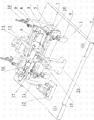
Fig. 1 is stereographic map structural representation of the present invention;
Fig. 2 is the mounting structure schematic diagram of simulation frame, axial tubing string installing plate assembly, pressing tongs, pressing tongs support;
Fig. 3 is the structural representation of gap of the present invention go-no go gauge.
Embodiment
See Fig. 1~Fig. 3, it comprises base plate 1, the position, wherein three angles of base plate is respectively arranged with standard sleeve 2, simulation frame 3 is supported on the upper surface of base plate 1, simulation frame 3 is oblique layout, it comprises the high platform 4 of upside, low 5 of downside and middle side transition bench 6, the high platform 4 of upside of simulation frame 3, the front end that downside is low 5, rear end is respectively arranged with the locating convex block 7 of evagination, the evagination distance of locating convex block 7 is 3mm, under detected state, the upper surface of locating convex block 7 is close in the lower surface of axial tubing string installing plate assembly 8, base plate 1 is provided with pressing tongs support 9 corresponding to the correspondence position of locating convex block 7, each pressing tongs support 9 is anchored on base plate 1, pressing tongs support 9 connects pressing tongs 10, pressing tongs 10 correspondences under detected state press-fit in the upper surface of the axial tubing string installing plate assembly 8 of the position of this side locating convex block 7, the front end of simulation frame 3 is provided with positive stop 11, one end of positive stop 11 is fastenedly connected positive stop base 12, positive stop base 12 is anchored on base plate 1, 8 front end faces of the axial tubing string installing plate assembly under detected state are close to positive stop 11, medium position corresponding to axial tubing string installing plate assembly 8 is provided with turnover panel 13, the corresponding platform trap door support 14 that connects of turnover panel 13, platform trap door support 14 is anchored on base plate 1, platform trap door support 14 is positioned at high platform 5 position side of upside of simulation frame 1, the upper surface, middle part of axial tubing string installing plate assembly 8 is pressed in the lower surface of the turnover panel 13 under detected state, base plate 1 position corresponding to middle-end of low 5 of the downside of simulation frame 3 is provided with middle part platform trap door support 15, middle part platform trap door support 15 correspondences are connected with middle part turnover panel 16, the below of middle part turnover panel 16 is fastened with simulated block 17, the upper surface, middle part that is positioned at low 5 positions of downside of axial tubing string installing plate assembly 8 is pressed in the lower surface of the simulated block 17 under detected state, on the middle side transition bench 6 of simulation frame 3, positioning hole groove 20 places of corresponding axial tubing string installing plate assembly 8 are fitted with respectively register pin 18, it also comprises gap go-no go gauge 19, the butt diameter of gap go-no go gauge 19 is 3.7mm, taper end diameter is 2.3mm.
Claims (1)
1. the cubing structure of an axial tubing string installing plate assembly, it is characterized in that: it comprises base plate, the position, wherein three angles of described base plate is respectively arranged with standard sleeve, simulation frame is supported on the upper surface of described base plate, described simulation frame is oblique layout, it comprises the high platform of upside, low of downside and middle side transition bench, the high platform of upside of described simulation frame, the front end that downside is low, rear end is respectively arranged with the locating convex block of evagination, the evagination distance of described locating convex block is 3mm, under detected state, the upper surface of described locating convex block is close in the lower surface of axial tubing string installing plate assembly, described base plate is provided with pressing tongs support corresponding to the correspondence position of described locating convex block, described in each, pressing tongs support is anchored on described base plate, described pressing tongs support connects pressing tongs, described pressing tongs correspondence under detected state press-fits in the upper surface of the described axial tubing string installing plate assembly of the position of locating convex block described in this side, the front end of described simulation frame is provided with positive stop, one end of described positive stop is fastenedly connected positive stop base, described positive stop base is anchored on described base plate, the front end face of the described axial tubing string installing plate assembly under detected state is close to described positive stop, medium position corresponding to described axial tubing string installing plate assembly is provided with turnover panel, the corresponding platform trap door support that connects of described turnover panel, described platform trap door support is anchored on described base plate, described platform trap door support is positioned at the high platform position side of upside of described simulation frame, the upper surface, middle part of described axial tubing string installing plate assembly is pressed in the lower surface of the described turnover panel under detected state, the base plate position corresponding to middle-end of low of the downside of described simulation frame is provided with middle part platform trap door support, described middle part platform trap door support correspondence is connected with middle part turnover panel, the below of described middle part turnover panel is fastened with simulated block, the upper surface, middle part that is positioned at low position of described downside of described axial tubing string installing plate assembly is pressed in the lower surface of the described simulated block under detected state, on the middle side transition bench of described simulation frame, the positioning hole groove place of corresponding described axial tubing string installing plate assembly is fitted with respectively register pin, it also comprises gap go-no go gauge, the butt diameter of described gap go-no go gauge is 3.7mm, taper end diameter is 2.3mm.
Priority Applications (1)
| Application Number | Priority Date | Filing Date | Title |
|---|---|---|---|
| CN201310509598.2A CN103528466A (en) | 2013-10-25 | 2013-10-25 | Detecting tool structure of axial pipe column mounting plate assembly |
Applications Claiming Priority (1)
| Application Number | Priority Date | Filing Date | Title |
|---|---|---|---|
| CN201310509598.2A CN103528466A (en) | 2013-10-25 | 2013-10-25 | Detecting tool structure of axial pipe column mounting plate assembly |
Publications (1)
| Publication Number | Publication Date |
|---|---|
| CN103528466A true CN103528466A (en) | 2014-01-22 |
Family
ID=49930675
Family Applications (1)
| Application Number | Title | Priority Date | Filing Date |
|---|---|---|---|
| CN201310509598.2A Pending CN103528466A (en) | 2013-10-25 | 2013-10-25 | Detecting tool structure of axial pipe column mounting plate assembly |
Country Status (1)
| Country | Link |
|---|---|
| CN (1) | CN103528466A (en) |
Cited By (2)
| Publication number | Priority date | Publication date | Assignee | Title |
|---|---|---|---|---|
| CN108827124A (en) * | 2018-09-03 | 2018-11-16 | 宁海县正达模塑有限公司 | A kind of engine support arm detection device |
| CN109000532A (en) * | 2018-08-17 | 2018-12-14 | 上海芃佳精密机械科技有限公司 | A kind of multimode group Quick detection tool |
-
2013
- 2013-10-25 CN CN201310509598.2A patent/CN103528466A/en active Pending
Cited By (3)
| Publication number | Priority date | Publication date | Assignee | Title |
|---|---|---|---|---|
| CN109000532A (en) * | 2018-08-17 | 2018-12-14 | 上海芃佳精密机械科技有限公司 | A kind of multimode group Quick detection tool |
| CN109000532B (en) * | 2018-08-17 | 2020-08-18 | 上海芃佳智能科技股份有限公司 | Multi-module quick detection tool |
| CN108827124A (en) * | 2018-09-03 | 2018-11-16 | 宁海县正达模塑有限公司 | A kind of engine support arm detection device |
Similar Documents
| Publication | Publication Date | Title |
|---|---|---|
| CN203534392U (en) | Detecting tool structure of axial pipe column mounting plate assembly | |
| CN103630048A (en) | Checking fixture structure of front-wall middle side sheet metal component | |
| CN103528466A (en) | Detecting tool structure of axial pipe column mounting plate assembly | |
| CN103528480A (en) | Detection device structure of upper B pillar reinforcing plate assembly | |
| CN203534460U (en) | Detection device structure of A pillar reinforcing plate | |
| CN203811067U (en) | Testing fixture structure for rear bumper | |
| CN103629991A (en) | Test tool structure for bottom back plate | |
| CN103630000A (en) | Checking fixture structure for vehicle body front side reinforcing plate | |
| CN103528468A (en) | Detection device structure of A pillar reinforcing plate | |
| CN103644816A (en) | Gauge structure for front and rear door and window frame assembly | |
| CN203534461U (en) | Detection device structure of upper B pillar reinforcing plate assembly | |
| CN103629998A (en) | Checking fixture structure for vehicle body outer side reinforcing plate | |
| CN203534401U (en) | Gauge structure of bottom backboard | |
| CN203657703U (en) | Back door glass rear guide rail detection tool structure | |
| CN103629995A (en) | Detection tool structure of rear floor connecting longitudinal beam | |
| CN203534414U (en) | Gauge structure of rear-floor connection longitudinal beam | |
| CN103630005A (en) | Measuring tool structure of central channel front reinforcing plate assembly | |
| CN203572369U (en) | Checking fixture structure of side wall skin reinforcement plate | |
| CN203534415U (en) | Gauge structure of vehicle body front-side reinforcing plate | |
| CN203534458U (en) | A testing fixture structure for a front door glass upper guide rail | |
| CN203534483U (en) | Gauge structure of front-rear sash assembly | |
| CN103630007A (en) | Detection tool structure of rear wheel hood outside plate | |
| CN103630047A (en) | Checking fixture structure for vehicle body top reinforcement part | |
| CN103629994A (en) | Checking fixture structure for vehicle body back side reinforcing plate | |
| CN203534410U (en) | Gauge structure of right-side B pillar |
Legal Events
| Date | Code | Title | Description |
|---|---|---|---|
| C06 | Publication | ||
| PB01 | Publication | ||
| WD01 | Invention patent application deemed withdrawn after publication |
Application publication date: 20140122 |
|
| WD01 | Invention patent application deemed withdrawn after publication |