CN103499927A - Position control system of direct-current servo motor - Google Patents
Position control system of direct-current servo motor Download PDFInfo
- Publication number
- CN103499927A CN103499927A CN201310438001.XA CN201310438001A CN103499927A CN 103499927 A CN103499927 A CN 103499927A CN 201310438001 A CN201310438001 A CN 201310438001A CN 103499927 A CN103499927 A CN 103499927A
- Authority
- CN
- China
- Prior art keywords
- servo motor
- ball screw
- control system
- position control
- rotational speed
- Prior art date
- Legal status (The legal status is an assumption and is not a legal conclusion. Google has not performed a legal analysis and makes no representation as to the accuracy of the status listed.)
- Granted
Links
- 238000006073 displacement reaction Methods 0.000 claims abstract description 46
- 238000001514 detection method Methods 0.000 claims abstract description 12
- 230000008878 coupling Effects 0.000 claims description 10
- 238000010168 coupling process Methods 0.000 claims description 10
- 238000005859 coupling reaction Methods 0.000 claims description 10
- 238000006243 chemical reaction Methods 0.000 claims description 7
- 239000003638 chemical reducing agent Substances 0.000 claims description 6
- 230000033001 locomotion Effects 0.000 claims description 6
- 230000008859 change Effects 0.000 claims description 5
- 238000005096 rolling process Methods 0.000 claims description 5
- 238000011897 real-time detection Methods 0.000 claims 1
- 238000010586 diagram Methods 0.000 description 6
- 230000007246 mechanism Effects 0.000 description 6
- 230000009977 dual effect Effects 0.000 description 3
- 230000005540 biological transmission Effects 0.000 description 2
- 238000005516 engineering process Methods 0.000 description 2
- 230000005226 mechanical processes and functions Effects 0.000 description 2
- 238000000034 method Methods 0.000 description 2
- 230000008054 signal transmission Effects 0.000 description 2
- 238000004458 analytical method Methods 0.000 description 1
- 230000007547 defect Effects 0.000 description 1
- 238000005265 energy consumption Methods 0.000 description 1
- 238000009776 industrial production Methods 0.000 description 1
- 238000009434 installation Methods 0.000 description 1
- 238000004519 manufacturing process Methods 0.000 description 1
- 239000000463 material Substances 0.000 description 1
- 239000002184 metal Substances 0.000 description 1
- 238000004377 microelectronic Methods 0.000 description 1
- 229910052755 nonmetal Inorganic materials 0.000 description 1
- 230000008569 process Effects 0.000 description 1
- 238000006467 substitution reaction Methods 0.000 description 1
Images


Landscapes
- Control Of Position Or Direction (AREA)
- Control Of Direct Current Motors (AREA)
Abstract
Description
技术领域technical field
本发明涉及自动控制技术领域,更具体地,涉及一种直流伺服电机位置控制系统。The invention relates to the technical field of automatic control, and more specifically, to a position control system of a DC servo motor.
背景技术Background technique
随着科学技术和工业生产的发展,对机械产品不时提出新要求,除了优质、高效、低能耗、低廉价格之外,突出的需求是实现性能优越的、适应高精度要求的机械功能,而高精度的机械系统离不开自动化的位置控制机构。With the development of science and technology and industrial production, new requirements are put forward for mechanical products from time to time. In addition to high quality, high efficiency, low energy consumption, and low price, the outstanding demand is to achieve mechanical functions with superior performance and high precision requirements. A precise mechanical system is inseparable from an automated position control mechanism.
位置控制系统是自动控制系统中的一类,随着微电子技术和计算机技术的飞速发展,它几乎应用到了社会生活中的各个领域,极大地促进了生产力的发展。整个控制系统功能的实现不仅包括控制算法的实现,而且包括执行机构的设计。执行机构的选用和设计,就是为了实现特定的机械功能,它是实现整个控制系统功能的最基本环节,对整个控制系统功能的实现起着至关重要的作用。执行机构设计的好坏,直接影响整个系统的性能、效率和成本。Position control system is a kind of automatic control system. With the rapid development of microelectronics and computer technology, it is applied to almost every field of social life, which greatly promotes the development of productivity. The realization of the function of the whole control system includes not only the realization of the control algorithm, but also the design of the executive mechanism. The selection and design of the actuator is to achieve specific mechanical functions. It is the most basic link to realize the functions of the entire control system and plays a vital role in the realization of the functions of the entire control system. The quality of the design of the actuator directly affects the performance, efficiency and cost of the entire system.
伺服电机分为直流伺服电机和交流伺服电机两种,在位置控制系统中,由于直流伺服电机具有优良的调速性能,能在大范围内平滑调速、起动、制动和正反转,并且易于各种控制规律的实现。因而直流伺服电机位置控制系统应用较为广泛。Servo motors are divided into two types: DC servo motors and AC servo motors. In the position control system, due to the excellent speed regulation performance of DC servo motors, they can smoothly adjust speed, start, brake and forward and reverse in a wide range, and are easy to use. Implementation of various control laws. Therefore, the position control system of DC servo motor is widely used.
但是,现有的直流伺服电机位置控制系统主要集中于对电机本身的位置控制;但在实际应用当中,位置控制还应该包括对在直流伺服电机驱动下的执行机构的位置精确控制。另一方面,现有的位置控制系统往往只能实现线位移的位置检测和控制,不能实现角位移条件下的检测和控制,使现有位置控制系统的功能和应用存在较大的局限性。However, the existing DC servo motor position control systems mainly focus on the position control of the motor itself; but in practical applications, position control should also include precise control of the position of the actuator driven by the DC servo motor. On the other hand, the existing position control systems often can only realize the position detection and control of linear displacement, but cannot realize the detection and control under the condition of angular displacement, which makes the function and application of the existing position control system have great limitations.
发明内容Contents of the invention
针对现有技术中的上述缺陷,本发明提供了一种直流伺服电机的位置控制系统。该系统实现了对直流伺服电机执行机构的位置和转速的双闭环控制,构成了一个具有双重功能的闭环控制系统,能够实现精确的位置控制和限位功能,适用于多种实际应用。Aiming at the above-mentioned defects in the prior art, the present invention provides a position control system of a DC servo motor. The system realizes the double closed-loop control of the position and speed of the DC servo motor actuator, and constitutes a closed-loop control system with dual functions, which can realize precise position control and limit functions, and is suitable for many practical applications.
本发明所述直流伺服电机的位置控制系统,其特征在于,包括控制装置、驱动装置、检测装置及执行装置;所述控制装置包括PC机,用于根据预定控制算法向驱动装置输出控制信号;所述驱动装置包括直流伺服电机驱动器,用于根据所述控制信号改变执行装置中的直流伺服电机的输入电压,从而控制直流伺服电机的转速;所述执行装置包括直流伺服电机、减速器、联轴器、滚珠丝杠和滚珠丝杠螺母,直流伺服电机通过减速器及联轴器连接滚珠丝杠,滚珠丝杠与滚珠丝杠螺母相匹配,并且滚珠丝杠螺母与运动部件联接;其中直流伺服电机在所述直流伺服电机驱动器提供的所述输入电压下转动,使所述滚珠丝杠转动,从而带动滚珠丝杠螺母及运动部件移动;所述检测装置包括位移传感器及信号转换接口电路,所述位移传感器实时检测执行装置的滚珠丝杠螺母的位移量,并通过信号转换接口电路将所述位移量转换为数字信号输入所述PC机;其中,所述PC机根据所述位移量与预定位移量之差值按照所述预定控制算法输出所述控制信号,直至所述滚珠丝杠螺母达到预定位移量。The position control system of the DC servo motor of the present invention is characterized in that it includes a control device, a drive device, a detection device and an execution device; the control device includes a PC, which is used to output a control signal to the drive device according to a predetermined control algorithm; The drive device includes a DC servo motor driver, which is used to change the input voltage of the DC servo motor in the execution device according to the control signal, thereby controlling the speed of the DC servo motor; the execution device includes a DC servo motor, a reducer, a coupling Shaft, ball screw and ball screw nut, the DC servo motor is connected to the ball screw through a reducer and a coupling, the ball screw matches the ball screw nut, and the ball screw nut is connected to the moving parts; The servo motor rotates under the input voltage provided by the DC servo motor driver, so that the ball screw rotates, thereby driving the ball screw nut and moving parts to move; the detection device includes a displacement sensor and a signal conversion interface circuit, The displacement sensor detects the displacement of the ball screw nut of the actuator in real time, and converts the displacement into a digital signal through a signal conversion interface circuit and inputs it to the PC; wherein, the PC is based on the displacement and The difference between the predetermined displacement amounts outputs the control signal according to the predetermined control algorithm until the ball screw nut reaches the predetermined displacement amount.
优选的是,所述检测装置还包括分别设置在运动部件行程的起点和终点位置上的第一限位开关和第二限位开关,当所述运动部件达到其行程起点和终点的极限位置时,所述第一限位开关和第二限位开关由常开状态转为闭合;所述直流伺服电机驱动器检测所述第一限位开关和第二限位开关的状态,并且在当第一限位开关和第二限位开关闭合后向直流伺服电机输出0V电压,从而使所述直流伺服电机停止转动。Preferably, the detection device further includes a first limit switch and a second limit switch respectively arranged at the starting point and end position of the stroke of the moving part, when the moving part reaches the limit position of the starting point and the end point of the stroke , the first limit switch and the second limit switch are turned from normally open to closed; the DC servo motor driver detects the state of the first limit switch and the second limit switch, and when the first After the limit switch and the second limit switch are closed, a 0V voltage is output to the DC servo motor, so that the DC servo motor stops rotating.
优选的是,所述位置控制系统还包括转速闭环控制装置,所述转速闭环控制装置包括转速传感器,用于实时检测直流伺服电机的转速,并将转速值反馈至所述PC机;所述PC机通过所述直流伺服电机驱动器控制直流伺服电机的转速,直至其达到预定转速。Preferably, the position control system further includes a rotational speed closed-loop control device, and the rotational speed closed-loop control device includes a rotational speed sensor for detecting the rotational speed of the DC servo motor in real time and feeding back the rotational speed value to the PC; the PC The machine controls the rotation speed of the DC servo motor through the DC servo motor driver until it reaches a predetermined rotation speed.
进一步优选的是,所述转速传感器采用磁电式转速传感器、霍尔式转速传感器或光电式转速传感器中的任意一种。Further preferably, the rotational speed sensor is any one of a magnetoelectric rotational speed sensor, a Hall-type rotational speed sensor or a photoelectric rotational speed sensor.
优选的是,所述执行装置还包括圆柱形附加导轨,用于约束所述滚珠丝杠螺母的旋转运动从而使其保持直线移动;并且圆柱形附加导轨上设置与其相配合并联接所述滚珠丝杠螺母的直线滚动轴承。Preferably, the actuator further includes a cylindrical additional guide rail, which is used to constrain the rotation of the ball screw nut so as to keep it moving in a straight line; Linear rolling bearings for nuts.
优选的是,所述滚珠丝杠的两端各以一个角接触球轴承双向固定支撑。Preferably, both ends of the ball screw are bidirectionally fixedly supported by an angular contact ball bearing.
进一步优选的是,所述滚珠丝杠的两端分别固定在丝杠支撑架上,并且丝杠支撑架的外侧设置端盖,在所述丝杠支撑架和端盖之间设置弹性调整垫片,所述弹性调整垫片用于改变端盖与丝杠支撑架之间的距离来调整所述角接触球轴承的游隙。Further preferably, the two ends of the ball screw are respectively fixed on the screw support frame, and the outer side of the screw support frame is provided with an end cover, and an elastic adjusting gasket is arranged between the screw support frame and the end cover , the elastic adjusting gasket is used to change the distance between the end cover and the screw support frame to adjust the clearance of the angular contact ball bearing.
优选的是,所述执行装置的联轴器包括齿盘和套筒两部分;所述齿盘与直流伺服电机的电机轴固定联接在一起,所述套筒联接齿盘与滚珠丝杠的丝杠轴,同时套筒可以在丝杠轴上轴向移动,以便在构成转速闭环控制时使滚珠丝杠与齿盘脱离。Preferably, the coupling of the actuator includes two parts: a gear plate and a sleeve; the gear plate is fixedly coupled with the motor shaft of the DC servo motor, and the sleeve connects the gear plate and the wire of the ball screw. At the same time, the sleeve can move axially on the screw shaft so that the ball screw can be separated from the chainring when forming a closed-loop control of the speed.
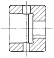
进一步优选的是,所述套筒包括键槽和销孔,并且套筒与滚珠丝杠通过所述键槽实现键联接,且套筒与齿盘之间通过所述销孔进行销联接。Further preferably, the sleeve includes a key groove and a pin hole, and the sleeve and the ball screw are keyed through the key groove, and the sleeve and the chainring are pinned through the pin hole.
优选的是,所述执行装置还包括底板,在底板上固定电机支撑架、丝杠支撑架、位移传感器;所述底板的底面设置支撑脚;并且所述电机支撑架、丝杠支撑架与底板之间通过定位销固定。Preferably, the execution device also includes a bottom plate on which the motor support frame, the screw support frame, and the displacement sensor are fixed; the bottom surface of the bottom plate is provided with supporting feet; and the motor support frame, the screw support frame and the bottom plate fixed by positioning pins.
可见,通过本发明,可以对直流伺服电机执行机构的位置和转速实现双闭环控制,构成了一个具有双重功能的闭环控制系统,能够实现精确的位置控制和限位功能,适用于多种实际应用。It can be seen that through the present invention, double closed-loop control can be realized for the position and speed of the DC servo motor actuator, forming a closed-loop control system with dual functions, which can realize precise position control and limit function, and is suitable for various practical applications .
附图说明Description of drawings
下面结合附图和具体实施方式对本发明作进一步详细的说明:Below in conjunction with accompanying drawing and specific embodiment the present invention will be described in further detail:
图1是本发明实施例的位置控制系统整体结构示意图;1 is a schematic diagram of the overall structure of a position control system according to an embodiment of the present invention;
图2是本发明实施例的执行装置装配结构示意图;Fig. 2 is a schematic diagram of the assembly structure of the execution device according to the embodiment of the present invention;
图3A-3B是本发明实施例的端盖结构示意图;3A-3B are schematic diagrams of the end cap structure of the embodiment of the present invention;
图4A-4B是本发明实施例的套筒结构示意图。4A-4B are schematic diagrams of the sleeve structure of the embodiment of the present invention.
具体实施方式Detailed ways
为了使本技术领域的人员更好地理解本发明的技术方案,并使本发明的上述目的、特征和优点能够更加明显易懂,下面结合实施例及实施例附图对本发明作进一步详细的说明。In order to enable those skilled in the art to better understand the technical solution of the present invention, and to make the above-mentioned purpose, features and advantages of the present invention more obvious and understandable, the present invention will be further described in detail below in conjunction with the embodiments and accompanying drawings .
图1是本发明实施例的位置控制系统整体结构示意图。本发明所述直流伺服电机的位置控制系统包括控制装置、驱动装置、检测装置及执行装置。所述控制装置包括PC机,用于根据预定控制算法向驱动装置输出控制信号;所述驱动装置包括直流伺服电机驱动器,用于根据所述控制信号改变执行装置中的直流伺服电机的输入电压,从而控制直流伺服电机的转速;PC机与直流伺服电机驱动器通过并口和串口彼此相连并执行数据指令形式的控制信号传输,同时PC机的信号转换接口包括AC6011型PCI槽及D/A,A/D转换器,其中D/A转换器连接直流伺服电机驱动器的模拟口,对直流伺服电机驱动器提供模拟格式的控制信号传输。位置控制系统的执行装置包括直流伺服电机、减速器、联轴器、滚珠丝杠和滚珠丝杠螺母,直流伺服电机通过减速器及联轴器连接滚珠丝杠,滚珠丝杠与滚珠丝杠螺母相匹配,并且滚珠丝杠螺母与运动部件联接;其中直流伺服电机在所述直流伺服电机驱动器提供的所述输入电压下转动,使所述滚珠丝杠转动,从而带动滚珠丝杠螺母及运动部件移动。所述检测装置包括位移传感器及信号转换接口电路,所述位移传感器实时检测执行装置的滚珠丝杠螺母的位移量,并通过信号转换接口电路的A/D转换器将所述位移量转换为数字信号输入所述PC机;其中,所述PC机根据所述位移量与预定位移量之差值按照所述预定控制算法输出所述控制信号,直至所述滚珠丝杠螺母达到预定位移量。所述检测装置还包括分别设置在运动部件行程的起点和终点位置上的限位开关1和限位开关2,当所述运动部件达到其行程起点和终点的极限位置时,所述限位开关1和限位开关2由常开状态转为闭合;所述直流伺服电机驱动器检测所述限位开关1和限位开关2的状态,并且在当任何一个限位开关闭合后向直流伺服电机输出0V电压,从而使所述直流伺服电机停止转动。FIG. 1 is a schematic diagram of the overall structure of a position control system according to an embodiment of the present invention. The position control system of the DC servo motor of the present invention includes a control device, a drive device, a detection device and an execution device. The control device includes a PC, which is used to output a control signal to the drive device according to a predetermined control algorithm; the drive device includes a DC servo motor driver, which is used to change the input voltage of the DC servo motor in the actuator according to the control signal, In order to control the speed of the DC servo motor; the PC and the DC servo motor driver are connected to each other through the parallel port and the serial port and execute the control signal transmission in the form of data instructions. At the same time, the signal conversion interface of the PC includes AC6011 PCI slot and D/A, A/ D converter, wherein the D/A converter is connected to the analog port of the DC servo motor driver, and provides analog format control signal transmission to the DC servo motor driver. The execution device of the position control system includes a DC servo motor, a reducer, a coupling, a ball screw and a ball screw nut. The DC servo motor is connected to the ball screw through a reducer and a coupling, and the ball screw and the ball screw nut Matched, and the ball screw nut is connected with the moving parts; wherein the DC servo motor rotates under the input voltage provided by the DC servo motor driver, so that the ball screw rotates, thereby driving the ball screw nut and the moving parts move. The detection device includes a displacement sensor and a signal conversion interface circuit. The displacement sensor detects the displacement of the ball screw nut of the actuator in real time, and converts the displacement into a digital value through the A/D converter of the signal conversion interface circuit. The signal is input to the PC; wherein, the PC outputs the control signal according to the predetermined control algorithm according to the difference between the displacement and the predetermined displacement until the ball screw nut reaches the predetermined displacement. The detection device also includes a limit switch 1 and a limit switch 2 respectively arranged at the starting point and end position of the stroke of the moving part. When the moving part reaches the limit position of the starting point and the end point of the stroke, the limit switch 1 and limit switch 2 turn from normally open to closed; the DC servo motor driver detects the state of the limit switch 1 and limit switch 2, and outputs to the DC servo motor when any limit switch is closed. 0V voltage, so that the DC servo motor stops rotating.
在整个直流伺服电机的位置控制系统中,由位移传感器实时检测滚珠丝杠螺母的位置,并将其反馈给PC机,PC机通过比较滚珠丝杠螺母的给定位移与实际位移之间的差值,根据一定的控制算法,向直流伺服电机驱动器输入一定的信号,直流伺服电机驱动器根据这个信号,通过改变直流伺服电机电枢的输入电压来控制直流伺服电机的转速,从而可双向改变滚珠丝杠螺母的线位移。这是一个逐步逼近控制系统的给定值的过程,直至滚珠丝杠螺母到达指定的位置为止。这里的转速传感器可采用磁电式转速传感器、霍尔式转速传感器或光电式转速传感器中的任意一种。In the position control system of the entire DC servo motor, the displacement sensor detects the position of the ball screw nut in real time and feeds it back to the PC. The PC compares the difference between the given displacement and the actual displacement of the ball screw nut. According to a certain control algorithm, a certain signal is input to the DC servo motor driver. According to this signal, the DC servo motor driver controls the speed of the DC servo motor by changing the input voltage of the DC servo motor armature, so that the ball wire can be changed in both directions. Linear displacement of the bar nut. This is a process of gradually approaching the given value of the control system until the ball screw nut reaches the specified position. The rotational speed sensor here may be any one of a magnetoelectric rotational speed sensor, a Hall-type rotational speed sensor or a photoelectric rotational speed sensor.
本发明所述位置控制系统还可以实现转速闭环控制,就是使执行机构的直流伺服电机的电机轴达到一个给定的转速。其实现的原理与位置闭环控制的实现大同小异,只是通过转速传感器不断检测电机轴的实时转速,并将其反馈给PC机,PC机再不断通过直流伺服电机驱动器控制伺服电机的转速,直至电机轴转速达到预定的转速,从而实现转速的闭环控制。The position control system of the present invention can also realize the closed-loop control of the rotational speed, that is to make the motor shaft of the DC servo motor of the actuator reach a given rotational speed. The principle of its realization is similar to that of position closed-loop control, except that the real-time speed of the motor shaft is continuously detected by the speed sensor and fed back to the PC, and the PC continues to control the speed of the servo motor through the DC servo motor driver until the motor shaft The speed reaches the predetermined speed, so as to realize the closed-loop control of the speed.
图2是本发明实施例的执行装置装配结构示意图。其中,1为直流伺服电机。2为电机支撑架,3为齿盘,4为套筒,5为透盖,6为丝杠左端支撑架,7为导杆,8为滚珠丝杠(螺杆),9为滚珠丝杠螺母,10为运动部件,11为丝杠右端支撑架,12为端盖,13为支撑脚,14为限位开关,15为底板,16为拉杆,17为压板,18为传感器支撑架,19为转速传感器,20为位移传感器。Fig. 2 is a schematic diagram of the assembly structure of the execution device according to the embodiment of the present invention. Among them, 1 is a DC servo motor. 2 is a motor support frame, 3 is a toothed plate, 4 is a sleeve, 5 is a transparent cover, 6 is a support frame at the left end of the screw, 7 is a guide rod, 8 is a ball screw (screw), 9 is a ball screw nut, 10 is the moving part, 11 is the support frame at the right end of the screw, 12 is the end cover, 13 is the support foot, 14 is the limit switch, 15 is the bottom plate, 16 is the pull rod, 17 is the pressure plate, 18 is the sensor support frame, 19 is the speed Sensor, 20 is a displacement sensor.
其中,导杆7为本发明的圆柱形附加导轨。根据运动学原理,所谓的导轨就是将运动构件约束到只有一个自由度的装置。这一个自由度可以是直线运动或者是回转运动。在本机构中,由于仅仅依靠滚珠丝杠并不能约束滚珠丝杠螺母作直线运动。因此,需增加一导杆7来约束滚珠丝杠螺母的旋转运动,使其作直线运动。考虑到导轨的加工制造难易程度,导轨的形式选择圆柱形。为了减少圆柱形导轨的磨损,可以采用直线滚动轴承与其配合的形式,在导杆7上设置与其相配合并联接所述滚珠丝杠螺母的直线滚动轴承这样不仅可以使运动部件的运动灵活自如,而且可以大大地提高传动效率,增加导轨的使用寿命。为提高传动刚度,合理地选择滚珠丝杠的支撑方式及正确的安装是很重要的,在本发明中,所述滚珠丝杠的两端各以一个角接触球轴承双向固定支撑。滚珠丝杠两端分别具有丝杠左端支撑架6和丝杠右端支撑架11。丝杠支撑架的外侧设置端盖12,图3A-3B是所述端盖的结构侧面半剖视图和正面视图。端盖的作用主要为密封轴承和调整轴承的游隙。为了减小外观尺寸,联接端盖与丝杠支撑架的螺钉选为内六角螺钉。因此,在设计端盖时,相应的设计为沉头孔。在所述丝杠支撑架和端盖之间设置弹性调整垫片,弹性调整垫片具有一定的弹性。它的主要作用是通过改变端盖或透盖与丝杆支撑架之间的距离来调整滚动轴承的游隙。调整垫片按材料的不同可以分为金属垫片和非金属垫片。Wherein, the guide rod 7 is a cylindrical additional guide rail of the present invention. According to the principle of kinematics, the so-called guide rail is a device that constrains the moving member to only one degree of freedom. This one degree of freedom can be linear motion or rotary motion. In this mechanism, the linear movement of the ball screw nut cannot be restrained only by the ball screw. Therefore, it is necessary to add a guide rod 7 to constrain the rotational movement of the ball screw nut so that it can move in a straight line. Considering the ease of processing and manufacturing the guide rail, the form of the guide rail is cylindrical. In order to reduce the wear of the cylindrical guide rail, a linear rolling bearing can be used to cooperate with it. A linear rolling bearing that cooperates with it and connects the ball screw nut is arranged on the guide rod 7. This can not only make the movement of the moving parts flexible and free, but also greatly Greatly improve the transmission efficiency and increase the service life of the guide rail. In order to improve the transmission rigidity, it is very important to reasonably select the support mode and correct installation of the ball screw. In the present invention, the two ends of the ball screw are bidirectionally fixedly supported by an angular contact ball bearing. The two ends of the ball screw are respectively provided with a supporting frame 6 at the left end of the leading screw and a supporting frame 11 at the right end of the leading screw. An end cover 12 is provided on the outer side of the screw support frame, and Fig. 3A-3B is a side half sectional view and a front view of the structure of the end cover. The function of the end cover is mainly to seal the bearing and adjust the clearance of the bearing. In order to reduce the appearance size, the screws connecting the end cover and the screw support frame are selected as inner hexagon screws. Therefore, when designing the end cap, the corresponding design is a countersunk hole. An elastic adjusting gasket is arranged between the screw support frame and the end cover, and the elastic adjusting gasket has certain elasticity. Its main function is to adjust the clearance of the rolling bearing by changing the distance between the end cover or the cover and the screw support frame. Adjusting shims can be divided into metal shims and non-metal shims according to different materials.
整个直流伺服电机位置控制系统执行机构的设计目的是构成线位移和角位移双闭环控制系统。应该注意到线位移和角位移闭环控制并不是同时实现的,而是互不交叉、互不影响的。这也就是说在构成线位移闭环控制的时候不存在角位移闭环控制,同样,在构成角位移闭环控制的时候不存在线位移闭环控制。但是当实现角位移闭环控制的时候,应该注意到执行机构的转速在没有到达预定转速时,机构的运动部件可能已经到达行程极限,而在种情况下是难以实现使机构转速到达预定转速这一目的的,即构成不了角位移的闭环控制。通过以上分析,在设计直流伺服电机位置控制系统执行机构时,为了实现角位移闭环控制,应该将丝杠轴与电机轴脱离。对此,可以将联轴器分为齿盘3和套筒4两部分。齿盘3与电机轴固定联接在一起,套筒4联接齿盘与丝杠轴,同时套筒4可以在丝杠轴上轴向移动,以便在构成转速闭环的制时使丝杠与齿盘脱离。图4A-4B示出了所述套筒的侧面剖视图和正面视图。所述套筒包括键槽和销孔,并且套筒与滚珠丝杠通过所述键槽实现键联接,且套筒与齿盘之间通过所述销孔进行销联接。The design purpose of the actuator of the entire DC servo motor position control system is to form a double closed-loop control system for linear displacement and angular displacement. It should be noted that the closed-loop control of linear displacement and angular displacement is not realized at the same time, but does not cross and influence each other. That is to say, there is no closed-loop control of angular displacement when the closed-loop control of linear displacement is formed, and similarly, there is no closed-loop control of linear displacement when the closed-loop control of angular displacement is formed. However, when realizing the closed-loop control of angular displacement, it should be noted that when the rotational speed of the actuator has not reached the predetermined rotational speed, the moving parts of the mechanism may have reached the stroke limit, and in this case it is difficult to achieve the speed of the mechanism to reach the predetermined rotational speed. The purpose is to form a closed-loop control of angular displacement. Through the above analysis, when designing the actuator of the DC servo motor position control system, in order to realize the closed-loop control of angular displacement, the screw shaft should be separated from the motor shaft. For this, the coupling can be divided into two parts, the
所述执行装置还包括底板15,在底板15上固定电机支撑架、丝杠支撑架、位移传感器;所述底板的底面设置支撑脚;并且所述电机支撑架、丝杠支撑架与底板之间通过定位销固定。底板实现了整个机构的平稳固定,以及各部件之间的精确定位。Described execution device also comprises
可见,通过本发明,可以对直流伺服电机执行机构的位置和转速实现双闭环控制,构成了一个具有双重功能的闭环控制系统,能够实现精确的位置控制和限位功能,适用于多种实际应用。It can be seen that through the present invention, double closed-loop control can be realized for the position and speed of the DC servo motor actuator, forming a closed-loop control system with dual functions, which can realize precise position control and limit function, and is suitable for various practical applications .
以上所述,仅为本发明的具体实施方式,本发明还可以应用在其它设备中;以上描述中的尺寸和数量均仅为参考性的,本领域技术人员可根据实际需要选择适当的应用尺寸,而不脱离本发明的范围。本发明的保护范围并不局限于此,任何熟悉本技术领域的技术人员在本发明揭露的技术范围内,可轻易想到的变化或替换,都应涵盖在本发明的保护范围之内。因此,本发明的保护范围应该以权利要求所界定的保护范围为准。The above is only a specific embodiment of the present invention, and the present invention can also be applied to other equipment; the dimensions and quantities in the above description are only for reference, and those skilled in the art can choose appropriate application dimensions according to actual needs , without departing from the scope of the present invention. The protection scope of the present invention is not limited thereto, and any changes or substitutions that can be easily conceived by those skilled in the art within the technical scope disclosed in the present invention shall fall within the protection scope of the present invention. Therefore, the protection scope of the present invention should be defined by the claims.
Claims (10)
Priority Applications (1)
| Application Number | Priority Date | Filing Date | Title |
|---|---|---|---|
| CN201310438001.XA CN103499927B (en) | 2013-09-14 | 2013-09-14 | A kind of DC servo motor position control system |
Applications Claiming Priority (1)
| Application Number | Priority Date | Filing Date | Title |
|---|---|---|---|
| CN201310438001.XA CN103499927B (en) | 2013-09-14 | 2013-09-14 | A kind of DC servo motor position control system |
Publications (2)
| Publication Number | Publication Date |
|---|---|
| CN103499927A true CN103499927A (en) | 2014-01-08 |
| CN103499927B CN103499927B (en) | 2016-05-18 |
Family
ID=49865147
Family Applications (1)
| Application Number | Title | Priority Date | Filing Date |
|---|---|---|---|
| CN201310438001.XA Expired - Fee Related CN103499927B (en) | 2013-09-14 | 2013-09-14 | A kind of DC servo motor position control system |
Country Status (1)
| Country | Link |
|---|---|
| CN (1) | CN103499927B (en) |
Cited By (14)
| Publication number | Priority date | Publication date | Assignee | Title |
|---|---|---|---|---|
| CN105181906A (en) * | 2015-10-10 | 2015-12-23 | 中国石油大学(华东) | Testing device for researching influence of liquid level to fluid sloshing motion |
| CN106171833A (en) * | 2016-07-11 | 2016-12-07 | 北京航空航天大学 | A kind of energy-efficient irrigation system and method changing flow based on height change |
| CN106598086A (en) * | 2017-02-27 | 2017-04-26 | 沈阳卓翼航空科技有限公司 | Agricultural unmanned-aerial-vehicle linear servo control device |
| CN108145528A (en) * | 2016-12-05 | 2018-06-12 | 新昌县嘉德科技发展有限公司 | A kind of control device of lathe |
| CN108483261A (en) * | 2018-04-20 | 2018-09-04 | 北京轩宇智能科技有限公司 | A kind of linear motion monitoring feedback module and its monitoring method and application |
| CN109282740A (en) * | 2018-11-01 | 2019-01-29 | 上海才义工程项目管理有限公司 | A kind of material detection system |
| CN109725223A (en) * | 2019-02-19 | 2019-05-07 | 上海达野智能科技有限公司 | Reducer assembly detection device |
| CN110597308A (en) * | 2019-09-06 | 2019-12-20 | 北京精密机电控制设备研究所 | a servo |
| CN110986666A (en) * | 2019-12-17 | 2020-04-10 | 西安奇维科技有限公司 | High-reliability electric bolt opening structure based on position detection and method thereof |
| CN112916664A (en) * | 2021-01-25 | 2021-06-08 | 新代科技(苏州)有限公司 | Double-drive coupling material pressing control mode |
| CN113700813A (en) * | 2020-05-21 | 2021-11-26 | 北京机械设备研究所 | Linear motion device with self-locking function and linear motion driving method |
| CN113885598A (en) * | 2021-10-12 | 2022-01-04 | 苏州铁马自动化科技有限公司 | Road strength meter control system and control method thereof |
| CN114474515A (en) * | 2021-12-09 | 2022-05-13 | 煤炭科学技术研究院有限公司 | Flat vulcanizing forming machine capable of realizing distance control |
| CN115276497A (en) * | 2022-08-03 | 2022-11-01 | 魅杰光电科技(上海)有限公司 | Motion system for wafer detection and control method thereof |
Citations (4)
| Publication number | Priority date | Publication date | Assignee | Title |
|---|---|---|---|---|
| JPH0876852A (en) * | 1994-09-02 | 1996-03-22 | Yaskawa Electric Corp | Cam device |
| US20030001530A1 (en) * | 2001-06-29 | 2003-01-02 | O'rourke Kenneth | Fail passive servo controller |
| CN101840064A (en) * | 2010-04-22 | 2010-09-22 | 中国科学院长春光学精密机械与物理研究所 | Control method and electric control device of direct current motor type force actuator |
| CN101587327B (en) * | 2008-05-21 | 2010-12-15 | 深圳市先阳软件技术有限公司 | Universal motion control system and control method on industrial control platform |
-
2013
- 2013-09-14 CN CN201310438001.XA patent/CN103499927B/en not_active Expired - Fee Related
Patent Citations (4)
| Publication number | Priority date | Publication date | Assignee | Title |
|---|---|---|---|---|
| JPH0876852A (en) * | 1994-09-02 | 1996-03-22 | Yaskawa Electric Corp | Cam device |
| US20030001530A1 (en) * | 2001-06-29 | 2003-01-02 | O'rourke Kenneth | Fail passive servo controller |
| CN101587327B (en) * | 2008-05-21 | 2010-12-15 | 深圳市先阳软件技术有限公司 | Universal motion control system and control method on industrial control platform |
| CN101840064A (en) * | 2010-04-22 | 2010-09-22 | 中国科学院长春光学精密机械与物理研究所 | Control method and electric control device of direct current motor type force actuator |
Non-Patent Citations (1)
| Title |
|---|
| 叶晓平: ""基于PC的开放式测控系统的研究"", 《制造技术与机床》, no. 8, 31 August 2004 (2004-08-31) * |
Cited By (18)
| Publication number | Priority date | Publication date | Assignee | Title |
|---|---|---|---|---|
| CN105181906A (en) * | 2015-10-10 | 2015-12-23 | 中国石油大学(华东) | Testing device for researching influence of liquid level to fluid sloshing motion |
| CN106171833A (en) * | 2016-07-11 | 2016-12-07 | 北京航空航天大学 | A kind of energy-efficient irrigation system and method changing flow based on height change |
| CN106171833B (en) * | 2016-07-11 | 2019-08-06 | 北京航空航天大学 | A high-efficiency and energy-saving irrigation system and method for changing flow based on height changes |
| CN108145528A (en) * | 2016-12-05 | 2018-06-12 | 新昌县嘉德科技发展有限公司 | A kind of control device of lathe |
| CN106598086A (en) * | 2017-02-27 | 2017-04-26 | 沈阳卓翼航空科技有限公司 | Agricultural unmanned-aerial-vehicle linear servo control device |
| CN108483261B (en) * | 2018-04-20 | 2024-02-27 | 北京轩宇智能科技有限公司 | Linear motion monitoring feedback module, and monitoring method and application thereof |
| CN108483261A (en) * | 2018-04-20 | 2018-09-04 | 北京轩宇智能科技有限公司 | A kind of linear motion monitoring feedback module and its monitoring method and application |
| CN109282740A (en) * | 2018-11-01 | 2019-01-29 | 上海才义工程项目管理有限公司 | A kind of material detection system |
| CN109725223A (en) * | 2019-02-19 | 2019-05-07 | 上海达野智能科技有限公司 | Reducer assembly detection device |
| CN110597308A (en) * | 2019-09-06 | 2019-12-20 | 北京精密机电控制设备研究所 | a servo |
| CN110986666A (en) * | 2019-12-17 | 2020-04-10 | 西安奇维科技有限公司 | High-reliability electric bolt opening structure based on position detection and method thereof |
| CN113700813A (en) * | 2020-05-21 | 2021-11-26 | 北京机械设备研究所 | Linear motion device with self-locking function and linear motion driving method |
| CN112916664A (en) * | 2021-01-25 | 2021-06-08 | 新代科技(苏州)有限公司 | Double-drive coupling material pressing control mode |
| CN113885598A (en) * | 2021-10-12 | 2022-01-04 | 苏州铁马自动化科技有限公司 | Road strength meter control system and control method thereof |
| CN114474515A (en) * | 2021-12-09 | 2022-05-13 | 煤炭科学技术研究院有限公司 | Flat vulcanizing forming machine capable of realizing distance control |
| CN114474515B (en) * | 2021-12-09 | 2024-07-05 | 煤炭科学技术研究院有限公司 | Flat vulcanization molding machine capable of realizing fixed-distance control |
| CN115276497A (en) * | 2022-08-03 | 2022-11-01 | 魅杰光电科技(上海)有限公司 | Motion system for wafer detection and control method thereof |
| CN115276497B (en) * | 2022-08-03 | 2024-03-01 | 魅杰光电科技(上海)有限公司 | Motion system for wafer detection and control method thereof |
Also Published As
| Publication number | Publication date |
|---|---|
| CN103499927B (en) | 2016-05-18 |
Similar Documents
| Publication | Publication Date | Title |
|---|---|---|
| CN103499927B (en) | A kind of DC servo motor position control system | |
| CN203871981U (en) | Linear displacement type electric steering engine | |
| CN103101049A (en) | Three-degree-of-freedom plane parallel mechanism with novel redundant drive branched-chain | |
| CN103939555B (en) | Many leading screws parallel drive unit | |
| CN204376607U (en) | A kind of electric cylinder | |
| CN103542055A (en) | Swivel nut combination unit | |
| CN201779228U (en) | Novel mechanical transmission mechanism | |
| CN203667951U (en) | Worm wheel spiral elevator | |
| CN103656797A (en) | Injection pump | |
| CN103863976A (en) | Worm wheel spiral elevator | |
| CN109728684B (en) | External integrated displacement sensor mounting mechanism adaptive to electromechanical actuator | |
| CN202240472U (en) | High-precision plane displacement mechanism | |
| CN104589121A (en) | Globoid cam type automatic tool change device | |
| CN103785719A (en) | Electromagnetic driving servo bending machine with planetary pin roller screw for transmission | |
| CN211053734U (en) | Robot integrated joint with sliding bearing at output end | |
| CN201321303Y (en) | Deviation rectifying device | |
| TWI627098B (en) | Electronic variable speed angle sensing structure | |
| CN103809615A (en) | Precise output positioning speed reducer and precise output positioning method thereof | |
| CN108757873B (en) | Linear uniform speed sine mechanism and turntable | |
| CN104482158A (en) | Accurate rotation mechanism | |
| CN204143752U (en) | A kind of cyclo drive mechanism apparatus for demonstrating | |
| CN210649500U (en) | High-precision high-rigidity turntable mechanism | |
| CN103878211B (en) | A kind of Electromagnetic Drive servo bender of Cycloidal pin-wheel drive mode | |
| CN203146729U (en) | Transformation device for transforming linear displacement into angular displacement | |
| CN209959819U (en) | Double-eccentric bearing linear motion driver |
Legal Events
| Date | Code | Title | Description |
|---|---|---|---|
| C06 | Publication | ||
| PB01 | Publication | ||
| C10 | Entry into substantive examination | ||
| SE01 | Entry into force of request for substantive examination | ||
| C14 | Grant of patent or utility model | ||
| GR01 | Patent grant | ||
| CF01 | Termination of patent right due to non-payment of annual fee |
Granted publication date: 20160518 Termination date: 20180914 |
|
| CF01 | Termination of patent right due to non-payment of annual fee |