CN103495776A - Automatic interior angle chamfering machine of piston ring - Google Patents
Automatic interior angle chamfering machine of piston ring Download PDFInfo
- Publication number
- CN103495776A CN103495776A CN201310471504.7A CN201310471504A CN103495776A CN 103495776 A CN103495776 A CN 103495776A CN 201310471504 A CN201310471504 A CN 201310471504A CN 103495776 A CN103495776 A CN 103495776A
- Authority
- CN
- China
- Prior art keywords
- piston ring
- interior angle
- knife bar
- panel
- delivery sheet
- Prior art date
- Legal status (The legal status is an assumption and is not a legal conclusion. Google has not performed a legal analysis and makes no representation as to the accuracy of the status listed.)
- Granted
Links
Images


Abstract
The invention discloses an automatic interior angle chamfering machine of a piston ring. The automatic interior angle chamfering machine comprises a lathe bed, a panel, a material loading component, a material feeding component, a material pressing component, a main shaft component and a feeding component. The panel is arranged on the lathe bed in a laying mode, the material loading component is installed on the panel, the material feeding component is installed on the panel, the material pressing component is installed on the panel and located beside the material loading component, and the main shaft component and the feeding component are located below the material pressing component. Through mutual action of the components, interior angle chamfering operation of the piston ring can be performed automatically without manual operation.
Description
Technical field
The present invention relates to a kind of piston ring manufacturing equipment field, especially a kind of piston ring is fallen to the equipment of interior angle.
Background technology
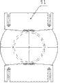
Piston ring is one of parts very crucial in automobile engine, in its manufacture process, has one extremely important its shape of inner circle chamfering process to see the product chamfering figure shown in accompanying drawing 1.The size of piston ring chamfering, uniformity not only will meet mounting process, and will consider the sealing property of piston ring in air cylinder sleeve of engine, prevent gas leakage, gas blowby, avoid premature wear.
The processing of piston ring inner circle chamfering is to adopt traditional cooked mode on industry always, i.e. a kind of half manual mode.In process, low, the chamfering angle size that processes of workpiece positioning precision is controlled badly, and the labour intensity of lack of homogeneity, particularly operating personnel is too large.
Therefore, need a kind of new technical scheme to address the above problem.
Summary of the invention
The objective of the invention is the deficiency existed for prior art, the piston ring automatic pouring interior angle machine that a kind of automaticity is high is provided.
For achieving the above object, piston ring automatic pouring interior angle machine of the present invention can adopt following technical scheme:
A kind of piston ring automatic pouring interior angle machine, comprise lathe bed, be layed in panel on lathe bed, be installed on charging parts on panel, be installed on panel feeding part, be installed on panel and be positioned at the other binder parts of charging parts, be positioned at spindle unit and the infeed mean of binder parts below; Described feeding part comprises delivery sheet and drives the drive unit of delivery sheet transverse movement, the feeding channel that described charging parts are provided with the host cavity of accommodating piston ring and are positioned at the host cavity bottom and pass in and out for delivery sheet, described delivery sheet enters feeding channel the piston ring of host cavity bottommost is pushed to the binder parts; Described binder parts are provided with the drive division that pressure head and drive ram move up and down; Spindle unit is provided with spindle driver that the main shaft, drive shaft of hollow rotate, is positioned at the bed die on main shaft and is positioned at the positioning module on bed die; Described infeed mean is provided with knife bar, the cutter that is installed on the knife bar top-side, the knife bar seat that is positioned at the knife bar bottom inserted in main shaft, the knife bar seat driver that drives the transverse movement of knife bar seat.
The using method of above-mentioned piston ring automatic pouring interior angle machine is: by some piston rings stacked pile up the charging parts host cavity in, making drive unit drive delivery sheet enter the host cavity bottom and promote nethermost piston ring moves and pushes in the positioning module of spindle unit to the binder parts, bed die is supporting this piston ring, thereby making drive division band dynamic head press piston ring downwards makes piston ring at bed die, pressure head, under the comprehensive function of positioning module, locate, thereby make spindle driver drive main shaft and rotate the piston ring rotation that drive simultaneously is arranged in positioning module, make knife bar seat driver drives cutter near and contact the inner surface cutting of falling the interior angle of this piston ring.
With background technology, compare, what piston ring automatic pouring interior angle machine of the present invention can be without the manually-operated automation carries out the piston ring operation of falling the interior angle.
Described spindle unit is provided with the restoring spring that is positioned at the bed die below, and when described pressure head is pressed spindle unit, restoring spring is compressed.After piston ring in positioning module machines, pressure head lifts, and positioning module and bed die are lifted by restoring spring, and delivery sheet promotes new piston ring again, and the piston ring that new piston ring will machine and playback is pushed open and new piston ring enters in positioning module again.Do not need so manually the piston ring processed to be taken out, can automatically take out the piston ring processed and insert new piston ring, form the batch machining effect of automation.
Feeding part also comprises connecting plate, optical axis, the slide block slided on optical axis, feeding panel seat; Wherein delivery sheet is arranged on the feeding panel seat; The feeding panel seat is arranged on connecting plate; Connecting plate and slide block are connected on optical axis and move back and forth, and connecting plate is connected with drive unit simultaneously.
The charging parts comprise backstay, pin, pin mounting blocks, blowing plate, and lever and backstay form host cavity, and wherein piston ring is placed on the blowing plate.
Spindle unit also comprises the large belt wheel be connected with main shaft, and the spindle driver be installed on lathe bed drives large belt wheel rotation by belt.
Infeed mean also comprises adjusting handle, slide plate, feed screw nut pair, line slideway, loading stand; Line slideway is positioned on loading stand and support skid, slide plate connection wire rod pair of nut; The knife bar seat is installed on slide plate; Knife bar seat driver is stepper motor, and stepper motor is secondary through the feed screw nut, line slideway drives slide plate and the guide rod seat motion; Between knife bar seat and knife bar, for being threaded, the knife bar below is provided with adjusting handle; Described knife bar is provided with gas hole.
Also comprise the guide parts that are installed on panel, the guide parts comprise a pair of guide plate that is positioned at the positioning module both sides.The guide parts can prevent that piston ring from departing from when being pushed.
It is most advanced and sophisticated that the head of described delivery sheet is provided with location, and when delivery sheet promotes piston ring, insert in the breach of piston ring at the tip, location.In the time of can when promoting piston ring, keeping like this stable of piston ring and can make each piston ring push spindle unit, the position of breach is identical, and the piston rings crudy processed is consistent.
The accompanying drawing explanation
Fig. 1 is the main TV structure schematic diagram of piston ring automatic pouring interior angle machine of the present invention.
Fig. 2 is the structural representation of the piston ring automatic pouring interior angle machine of vertical view 1 angle displaying.
Fig. 3 is the structural representation of feeding part in piston ring automatic pouring interior angle machine of the present invention.
Fig. 4 is the structural representation of charging parts in piston ring automatic pouring interior angle machine of the present invention.
Fig. 5 is the structural representation of guide parts in piston ring automatic pouring interior angle machine of the present invention.
Fig. 6 is the structural representation of binder parts in piston ring automatic pouring interior angle machine of the present invention.
Fig. 7 is the structural representation of spindle unit in piston ring automatic pouring interior angle machine of the present invention.
Fig. 8 is the structural representation of infeed mean in piston ring automatic pouring interior angle machine of the present invention.
Fig. 9 is the structural representation of the infeed mean of vertical view 8 angles displayings.
Figure 10 is the structural representation of delivery sheet in feeding part.
The specific embodiment
Below in conjunction with the drawings and specific embodiments, further illustrate the present invention, should understand these embodiment only is not used in and limits the scope of the invention for the present invention is described, after having read the present invention, those skilled in the art all fall within the application's claims limited range to the modification of the various equivalent form of values of the present invention.
Refer to shown in Fig. 1 and Fig. 2, piston ring automatic pouring interior angle machine comprises that lathe bed 1, panel 2, feeding part 3, charging parts 4, guide parts 5, binder parts 6, spindle unit 7, infeed mean 8, motor 9, small pulley 10, large belt wheel 11, digital control system 12 and related accessories form.Wherein infeed mean 8 is arranged on the bottom of lathe bed 1; Feeding part 3, spindle unit 7 are arranged on the bottom of panel 2; Charging parts 4, guide parts 5, binder parts 6 are arranged on the top of panel 2; Motor 9 is arranged on the side of lathe bed 1; Small pulley 10 is arranged on above motor 9; Large belt wheel 11 is arranged on above spindle unit 7.
Feeding part figure as shown in Figure 3: feeding part 3 comprises cylinder 31, connecting plate 32, slide block 33, optical axis 34, feeding panel seat 35, delivery sheet 36.Wherein delivery sheet 36 is arranged on feeding panel seat 35; Feeding panel seat 35 is arranged on connecting plate 32; Connecting plate 32 with can realize after 2 slide blocks 33 are connected moving back and forth on optical axis 34, connecting plate 32 is connected with the end of cylinder 31 simultaneously.Cylinder 31 is usingd compressed air as power realization reciprocating motion, finally makes delivery sheet move back and forth, to realize feeding, to return action.Please, in conjunction with shown in Figure 10, it is most advanced and sophisticated that the head of delivery sheet 36 is provided with location, and when delivery sheet 36 promotes piston ring 43, insert in the breach of piston ring at the tip, location
Charging component diagram as shown in Figure 4: charging parts 4 comprise backstay 42, pin 44, regulating handle 45, pin mounting blocks 46, blowing plate 47.Workpiece 43(piston ring wherein) be to be placed in above blowing plate 47; Rotate regulating handle 45, can adjust the distance of pin 44 bottom surfaces and blowing plate 47, make its height that remains on 1.5 times of piston rings, thereby make delivery sheet 36 in feeding part 3 when promoting forward 1 workpiece 43 of bottommost, pin 44 keeps top all workpiece 43 not to be pushed forward into.
Guide component diagram as shown in Figure 5: guide parts 5 comprise a pair of guide plate 51 that is installed on panel 2 and is positioned at the positioning module both sides, adjust guide plate 51 positions, and the workpiece 43 that delivery sheet 36 can be pushed forward is fixed on applicable position, spindle unit 7 tops.
Binder component diagram as shown in Figure 6: binder parts 6 comprise cylinder 61, guide rod 62, guide pin bushing 63, pressure head 64.Pressure head, under cylinder action, is pressed into workpiece 43 in spindle unit 7.
Spindle unit figure as shown in Figure 7: spindle unit 7 comprises positioning module 71, bed die 72, spring 73, main shaft 74.Wherein large belt wheel 11 is arranged on main shaft 74, thereby can drive main shaft 74 rotations; Positioning module 71 is arranged on can be in company with rotation therewith on main shaft 74, and there is large fillet its inner circle upper end, so that the importing of workpiece 43; After pressure head 64 is pressed into positioning module 71 by workpiece 43, pressure head 64, workpiece 43 and bed die 72 move downward together, until bed die 72 contacts with main shaft 74, at this moment when main shaft 74 starts to rotate, will drive bed die 72, positioning module 71, workpiece 43, pressure head 64 and rotatablely move together.Cutter 81 just can start to workpiece 43 close, carries out machining.After cutting completes, main shaft stops the rotation, and pressure head 64 unclamps and moves upward, at this moment bed die 72 moves up under acting force of the spring together with workpiece 43, until bed die 72 touches positioning module 71, at this moment, workpiece 43(piston ring) rest on the position equal with plane on positioning module 71.
Infeed mean figure as shown in Fig. 8 to Fig. 9: infeed mean 8 comprises the cutter of falling the interior angle 81, knife bar 82, knife bar seat 83, adjusting handle 84, slide plate 85, feed screw nut pair 86, stepper motor 87, line slideway 88, loading stand 89.Wherein digital control system control step motor 87 rotations, drive slide plate 85 front and back rectilinear motions through feed screw nut's pair 86, line slideway 88; Thereby drive knife bar 82, cutter 81 seesaw, realize the machining action.Adjusting handle 84 is vertical direction positions of adjusting knife bar 82, and knife bar is provided with pore, and by passing into compressed air, the action of blowing after cutting completes, dry up the iron filings that are attached to workpiece 43 surfaces.
Claims (10)
1. a piston ring automatic pouring interior angle machine is characterized in that: comprise lathe bed, be layed in panel on lathe bed, be installed on charging parts on panel, be installed on panel feeding part, be installed on panel and be positioned at the other binder parts of charging parts, be positioned at spindle unit and the infeed mean of binder parts below;
Described feeding part comprises delivery sheet and drives the drive unit of delivery sheet transverse movement, the feeding channel that described charging parts are provided with the host cavity of accommodating piston ring and are positioned at the host cavity bottom and pass in and out for delivery sheet, described delivery sheet enters feeding channel the piston ring of host cavity bottommost is pushed to the binder parts; Described binder parts are provided with the drive division that pressure head and drive ram move up and down; Spindle unit is provided with spindle driver that the main shaft, drive shaft of hollow rotate, is positioned at the bed die on main shaft and is positioned at the positioning module on bed die; Described infeed mean is provided with knife bar, the cutter that is installed on the knife bar top-side, the knife bar seat that is positioned at the knife bar bottom inserted in main shaft, the knife bar seat driver that drives the transverse movement of knife bar seat.
2. piston ring automatic pouring interior angle machine according to claim 1 is characterized in that: described spindle unit is provided with the restoring spring that is positioned at the bed die below, and when described pressure head is pressed spindle unit, restoring spring is compressed.
3. piston ring automatic pouring interior angle machine according to claim 1 and 2, it is characterized in that: feeding part also comprises connecting plate, optical axis, the slide block slided on optical axis, feeding panel seat; Wherein delivery sheet is arranged on the feeding panel seat; The feeding panel seat is arranged on connecting plate; Connecting plate and slide block are connected on optical axis and move back and forth, and connecting plate is connected with drive unit simultaneously.
4. piston ring automatic pouring interior angle machine according to claim 3 is characterized in that: the charging parts comprise backstay, pin, pin mounting blocks, blowing plate, and lever and backstay form host cavity, and wherein piston ring is placed on the blowing plate.
5. piston ring automatic pouring interior angle machine according to claim 1, it is characterized in that: spindle unit also comprises the large belt wheel be connected with main shaft, is installed on spindle driver on lathe bed and drives large belt wheel by belt and rotate.
6. piston ring automatic pouring interior angle machine according to claim 1, it is characterized in that: infeed mean also comprises adjusting handle, slide plate, feed screw nut pair, line slideway, loading stand; Line slideway is positioned on loading stand and support skid, slide plate connection wire rod pair of nut; The knife bar seat is installed on slide plate; Knife bar seat driver is stepper motor, and stepper motor is secondary through the feed screw nut, line slideway drives slide plate and the guide rod seat motion; Between knife bar seat and knife bar, for being threaded, the knife bar below is provided with adjusting handle; Described knife bar is provided with gas hole.
7. piston ring automatic pouring interior angle machine according to claim 1, it is characterized in that: also comprise the guide parts that are installed on panel, the guide parts comprise a pair of guide plate that is positioned at the positioning module both sides.
8. piston ring automatic pouring interior angle machine according to claim 3 is characterized in that: it is most advanced and sophisticated that the head of described delivery sheet is provided with location, when delivery sheet promotes piston ring in the most advanced and sophisticated breach that inserts piston ring in location.
9. the using method as the described piston ring automatic pouring of claim 1-8 any one interior angle machine, it is characterized in that: by some piston rings stacked pile up the charging parts host cavity in, making drive unit drive delivery sheet enter the host cavity bottom and promote nethermost piston ring moves and pushes in the positioning module of spindle unit to the binder parts, bed die is supporting this piston ring, thereby making drive division band dynamic head press piston ring downwards makes piston ring at bed die, pressure head, under the comprehensive function of positioning module, locate, thereby make spindle driver drive main shaft and rotate the piston ring rotation that drive simultaneously is arranged in positioning module, make knife bar seat driver drives cutter near and contact the inner surface cutting of falling the interior angle of this piston ring.
10. the using method of piston ring automatic pouring interior angle machine as claimed in claim 9, it is characterized in that: described spindle unit is provided with the restoring spring that is positioned at the bed die below, when described pressure head is pressed spindle unit, restoring spring is compressed, after piston ring in positioning module machines, pressure head lifts, positioning module and bed die are lifted by restoring spring, and delivery sheet promotes new piston ring again, and the piston ring that new piston ring will machine and playback is pushed open and new piston ring enters in positioning module again.
Priority Applications (1)
| Application Number | Priority Date | Filing Date | Title |
|---|---|---|---|
| CN201310471504.7A CN103495776B (en) | 2013-10-10 | 2013-10-10 | Automatic interior angle chamfering machine of piston ring |
Applications Claiming Priority (1)
| Application Number | Priority Date | Filing Date | Title |
|---|---|---|---|
| CN201310471504.7A CN103495776B (en) | 2013-10-10 | 2013-10-10 | Automatic interior angle chamfering machine of piston ring |
Publications (2)
| Publication Number | Publication Date |
|---|---|
| CN103495776A true CN103495776A (en) | 2014-01-08 |
| CN103495776B CN103495776B (en) | 2015-06-17 |
Family
ID=49861085
Family Applications (1)
| Application Number | Title | Priority Date | Filing Date |
|---|---|---|---|
| CN201310471504.7A Active CN103495776B (en) | 2013-10-10 | 2013-10-10 | Automatic interior angle chamfering machine of piston ring |
Country Status (1)
| Country | Link |
|---|---|
| CN (1) | CN103495776B (en) |
Cited By (1)
| Publication number | Priority date | Publication date | Assignee | Title |
|---|---|---|---|---|
| CN105834522A (en) * | 2016-05-09 | 2016-08-10 | 江苏苏扬包装股份有限公司 | Vertical single-piece hook R groove machine |
Citations (10)
| Publication number | Priority date | Publication date | Assignee | Title |
|---|---|---|---|---|
| KR20030028301A (en) * | 2001-09-29 | 2003-04-08 | 대우종합기계 주식회사 | Carriage supporting structure of manufacturing machine |
| JP2012130996A (en) * | 2010-12-22 | 2012-07-12 | Komy Co Ltd | Chamfering tool |
| CN202667819U (en) * | 2012-06-29 | 2013-01-16 | 仪征市润扬机械有限公司 | Material pressing device for automatic interior angle chamfering machine |
| CN202667818U (en) * | 2012-06-29 | 2013-01-16 | 仪征市润扬机械有限公司 | Rotary device of automatic radiusing machine |
| CN202701512U (en) * | 2012-07-23 | 2013-01-30 | 太仓市旭冉机械有限公司 | Chamfering machine for exterior angle processing |
| CN102909434A (en) * | 2012-10-16 | 2013-02-06 | 海盐忠明机械有限公司 | Automatic chamfering device of clamp plate |
| CN202726198U (en) * | 2012-11-06 | 2013-02-13 | 天津市中马骏腾精密机械制造有限公司 | Numerical control double-end chamfering machine |
| CN103100763A (en) * | 2013-03-01 | 2013-05-15 | 梁呈旺 | Automatic chamfering machine |
| JP2013116515A (en) * | 2011-12-01 | 2013-06-13 | Aron Kasei Co Ltd | Chamfering correction tool for pipe cut end |
| CN203592194U (en) * | 2013-10-10 | 2014-05-14 | 南京飞燕活塞环股份有限公司 | Automatic interior angle chamfering machine of piston ring |
-
2013
- 2013-10-10 CN CN201310471504.7A patent/CN103495776B/en active Active
Patent Citations (10)
| Publication number | Priority date | Publication date | Assignee | Title |
|---|---|---|---|---|
| KR20030028301A (en) * | 2001-09-29 | 2003-04-08 | 대우종합기계 주식회사 | Carriage supporting structure of manufacturing machine |
| JP2012130996A (en) * | 2010-12-22 | 2012-07-12 | Komy Co Ltd | Chamfering tool |
| JP2013116515A (en) * | 2011-12-01 | 2013-06-13 | Aron Kasei Co Ltd | Chamfering correction tool for pipe cut end |
| CN202667819U (en) * | 2012-06-29 | 2013-01-16 | 仪征市润扬机械有限公司 | Material pressing device for automatic interior angle chamfering machine |
| CN202667818U (en) * | 2012-06-29 | 2013-01-16 | 仪征市润扬机械有限公司 | Rotary device of automatic radiusing machine |
| CN202701512U (en) * | 2012-07-23 | 2013-01-30 | 太仓市旭冉机械有限公司 | Chamfering machine for exterior angle processing |
| CN102909434A (en) * | 2012-10-16 | 2013-02-06 | 海盐忠明机械有限公司 | Automatic chamfering device of clamp plate |
| CN202726198U (en) * | 2012-11-06 | 2013-02-13 | 天津市中马骏腾精密机械制造有限公司 | Numerical control double-end chamfering machine |
| CN103100763A (en) * | 2013-03-01 | 2013-05-15 | 梁呈旺 | Automatic chamfering machine |
| CN203592194U (en) * | 2013-10-10 | 2014-05-14 | 南京飞燕活塞环股份有限公司 | Automatic interior angle chamfering machine of piston ring |
Cited By (1)
| Publication number | Priority date | Publication date | Assignee | Title |
|---|---|---|---|---|
| CN105834522A (en) * | 2016-05-09 | 2016-08-10 | 江苏苏扬包装股份有限公司 | Vertical single-piece hook R groove machine |
Also Published As
| Publication number | Publication date |
|---|---|
| CN103495776B (en) | 2015-06-17 |
Similar Documents
| Publication | Publication Date | Title |
|---|---|---|
| CN102218547B (en) | Valve rod automatic machining machine | |
| CN203266231U (en) | Automatic feeding and blanking mechanism for machine tool | |
| CN105436898B (en) | A kind of chamfering rolling cut compounding machine of annular element | |
| CN205343337U (en) | Plank processing equipment with locate function | |
| CN106826288B (en) | A kind of device for clamping square cross | |
| CN202123248U (en) | Automatic processor for valve rod | |
| CN103394606A (en) | Full-automatic feeding device of punching machine | |
| JP3193764U (en) | Screw forming machine | |
| CN103331488A (en) | Diamond tool bit bottom surface grinding device | |
| CN105598293A (en) | Automatic shaft ribbing tool | |
| CN104084473A (en) | Automatic notching press | |
| CN104816029A (en) | Full-automatic reverser groove milling machine | |
| CN203330795U (en) | Diamond knife head face detecting device | |
| CN204524420U (en) | Single head automatic chamfering machine | |
| CN203592194U (en) | Automatic interior angle chamfering machine of piston ring | |
| CN204657587U (en) | A kind of edge milling machines | |
| CN106625047B (en) | Arc cutter grinding machine, tool clamp thereof and use method | |
| CN107009219B (en) | Lens processing device | |
| CN103495776B (en) | Automatic interior angle chamfering machine of piston ring | |
| CN109848582B (en) | Three-dimensional laser cutting machine of panel of bending | |
| CN103962895A (en) | Special large cutter grinder for bearing cutter | |
| CN203917924U (en) | Automatic ring pattern-etching machine | |
| CN202346345U (en) | Automatic feeding device for processing shaft sleeve of fan | |
| CN202147064U (en) | Automatic feeding and receiving tapping machine | |
| CN204818078U (en) | Spherical processing vehicle bed |
Legal Events
| Date | Code | Title | Description |
|---|---|---|---|
| C06 | Publication | ||
| PB01 | Publication | ||
| C10 | Entry into substantive examination | ||
| SE01 | Entry into force of request for substantive examination | ||
| C14 | Grant of patent or utility model | ||
| GR01 | Patent grant | ||
| PE01 | Entry into force of the registration of the contract for pledge of patent right | ||
| PE01 | Entry into force of the registration of the contract for pledge of patent right |
Denomination of invention: Automatic internal angle machine for piston ring Effective date of registration: 20201203 Granted publication date: 20150617 Pledgee: Bank of China Limited by Share Ltd. Lishui branch Pledgor: NANJING FEIYAN PISTON RING Co.,Ltd. Registration number: Y2020980008801 |