CN103477183A - Tire surface shape measuring device and tire surface shape measuring method - Google Patents
Tire surface shape measuring device and tire surface shape measuring method Download PDFInfo
- Publication number
- CN103477183A CN103477183A CN2012800190787A CN201280019078A CN103477183A CN 103477183 A CN103477183 A CN 103477183A CN 2012800190787 A CN2012800190787 A CN 2012800190787A CN 201280019078 A CN201280019078 A CN 201280019078A CN 103477183 A CN103477183 A CN 103477183A
- Authority
- CN
- China
- Prior art keywords
- tire
- watch region
- camera watch
- linear light
- shooting
- Prior art date
- Legal status (The legal status is an assumption and is not a legal conclusion. Google has not performed a legal analysis and makes no representation as to the accuracy of the status listed.)
- Pending
Links
- 238000000034 method Methods 0.000 title claims description 19
- 239000000284 extract Substances 0.000 claims abstract description 11
- 238000003384 imaging method Methods 0.000 claims description 30
- 238000005259 measurement Methods 0.000 abstract 2
- 238000001514 detection method Methods 0.000 description 23
- 238000012545 processing Methods 0.000 description 19
- 238000000605 extraction Methods 0.000 description 9
- 238000010586 diagram Methods 0.000 description 5
- 238000012546 transfer Methods 0.000 description 5
- 238000007689 inspection Methods 0.000 description 4
- 238000003556 assay Methods 0.000 description 3
- 238000011161 development Methods 0.000 description 3
- 238000006243 chemical reaction Methods 0.000 description 2
- 238000013075 data extraction Methods 0.000 description 2
- 238000009826 distribution Methods 0.000 description 2
- 238000005516 engineering process Methods 0.000 description 2
- 239000012467 final product Substances 0.000 description 2
- 238000012360 testing method Methods 0.000 description 2
- 241001269238 Data Species 0.000 description 1
- NINIDFKCEFEMDL-UHFFFAOYSA-N Sulfur Chemical compound [S] NINIDFKCEFEMDL-UHFFFAOYSA-N 0.000 description 1
- 239000005864 Sulphur Substances 0.000 description 1
- 238000000151 deposition Methods 0.000 description 1
- 230000023077 detection of light stimulus Effects 0.000 description 1
- 229910052736 halogen Inorganic materials 0.000 description 1
- 150000002367 halogens Chemical class 0.000 description 1
- 238000005286 illumination Methods 0.000 description 1
- 238000004519 manufacturing process Methods 0.000 description 1
- 238000012986 modification Methods 0.000 description 1
- 230000004048 modification Effects 0.000 description 1
- 238000012856 packing Methods 0.000 description 1
- 230000004304 visual acuity Effects 0.000 description 1
Images


Classifications
-
- H—ELECTRICITY
- H04—ELECTRIC COMMUNICATION TECHNIQUE
- H04N—PICTORIAL COMMUNICATION, e.g. TELEVISION
- H04N7/00—Television systems
- H04N7/18—Closed-circuit television [CCTV] systems, i.e. systems in which the video signal is not broadcast
-
- G—PHYSICS
- G01—MEASURING; TESTING
- G01B—MEASURING LENGTH, THICKNESS OR SIMILAR LINEAR DIMENSIONS; MEASURING ANGLES; MEASURING AREAS; MEASURING IRREGULARITIES OF SURFACES OR CONTOURS
- G01B11/00—Measuring arrangements characterised by the use of optical techniques
- G01B11/24—Measuring arrangements characterised by the use of optical techniques for measuring contours or curvatures
-
- B—PERFORMING OPERATIONS; TRANSPORTING
- B60—VEHICLES IN GENERAL
- B60C—VEHICLE TYRES; TYRE INFLATION; TYRE CHANGING; CONNECTING VALVES TO INFLATABLE ELASTIC BODIES IN GENERAL; DEVICES OR ARRANGEMENTS RELATED TO TYRES
- B60C19/00—Tyre parts or constructions not otherwise provided for
-
- G—PHYSICS
- G01—MEASURING; TESTING
- G01B—MEASURING LENGTH, THICKNESS OR SIMILAR LINEAR DIMENSIONS; MEASURING ANGLES; MEASURING AREAS; MEASURING IRREGULARITIES OF SURFACES OR CONTOURS
- G01B11/00—Measuring arrangements characterised by the use of optical techniques
- G01B11/24—Measuring arrangements characterised by the use of optical techniques for measuring contours or curvatures
- G01B11/25—Measuring arrangements characterised by the use of optical techniques for measuring contours or curvatures by projecting a pattern, e.g. one or more lines, moiré fringes on the object
- G01B11/2518—Projection by scanning of the object
- G01B11/2522—Projection by scanning of the object the position of the object changing and being recorded
-
- G—PHYSICS
- G01—MEASURING; TESTING
- G01M—TESTING STATIC OR DYNAMIC BALANCE OF MACHINES OR STRUCTURES; TESTING OF STRUCTURES OR APPARATUS, NOT OTHERWISE PROVIDED FOR
- G01M17/00—Testing of vehicles
- G01M17/007—Wheeled or endless-tracked vehicles
- G01M17/02—Tyres
-
- G—PHYSICS
- G01—MEASURING; TESTING
- G01M—TESTING STATIC OR DYNAMIC BALANCE OF MACHINES OR STRUCTURES; TESTING OF STRUCTURES OR APPARATUS, NOT OTHERWISE PROVIDED FOR
- G01M17/00—Testing of vehicles
- G01M17/007—Wheeled or endless-tracked vehicles
- G01M17/02—Tyres
- G01M17/027—Tyres using light, e.g. infrared, ultraviolet or holographic techniques
Abstract
The present invention detects the surface shape of each of tires having different sidewall surface thicknesses and tread surface widths with the same image resolution and high accuracy. This tire surface shape measuring device (1) captures an image of linear light applied to the surface of a tire (T), and measures the surface shape of the tire (T) on the basis of measurement signals extracted from the captured image of the linear light. The tire surface shape measuring device (1) is provided with an image capturing element (9) in which an image capturing surface for capturing the image of the linear light applied to the surface of the tire (T) is provided, an image capture area setting means (10) which sets an effective image capture area (A) provided with the length in the longitudinal direction of the image of the linear light on the image capturing surface such that all of the image formed on the image capture surface of the linear light is included, and a pixel data extracting means (11) which extracts a predetermined given number of measurement signals from the set effective image capture area (A).
Description
Technical field
The measured signal that the linear light that the present invention relates to the surface to exposing to tire is made a video recording, the photographed images based on from comprising linear light is extracted out is measured surface of tyre shape measuring apparatus and the surface of tyre process for measuring shape of the surface configuration of tire.
Background technology
In the past, when manufacturing tire, as the adding during shape after the sulphur operation checks of final operation, carried out the inspection of the surface configuration of tire.In recent years, this shape inspection is used the shape measuring apparatus that possesses sensor unit and robotization, the CCD filming apparatus that wherein this sensor unit is used lasing light emitter and picture that this laser is caused is made a video recording or CMOS filming apparatus etc.
In the shape of the use laser that adopts this shape measuring apparatus checks, irradiate the laser (linear light) of sheet to the tread as surface of tyre or side wall surface, and form light cut-out line on this face.Thereafter, with the shooting part of CCD filming apparatus, CMOS filming apparatus etc., this light cut-out line is made a video recording, the 3D shape of measuring surface of tyre by the cut-out of the light to shooting line application light cross-section method is checked.
For example, in the mensuration of the 3D shape of side wall surface, remove the normal concaveconvex shape caused because of character or identifier etc. by the 3D shape from obtaining in this wise, also detection side wall trickle concavo-convex bad and being checked exactly.
In addition, the exploitation of riding tire for vehicles in recent years, compare with existing tire, towards the tread width, broadens and the future development of while side wall surface attenuation.In other words, exploitation becomes large future development towards the difference of the thickness of the width of tread and side wall surface.And in recent years, tire size represents varied, the size of the tire that shape measuring apparatus must be tackled and shape have the trend of increase.
Correspondingly, in order to check the tire with various sizes and shape, as shape measuring apparatus, people have studied the structure of the tire for sizes is installed, or coordinate the size of the tire install and shape and change the structure of the position of sensor unit.
The prior art document
Patent documentation
Patent documentation 1: TOHKEMY 2003-240521 communique.
Summary of the invention
As mentioned above, the exploitation of riding tire for vehicles in recent years becomes large future development towards the difference of the thickness of the width of tread and side wall surface, and tire size also represents varied.The sensor unit that this means shape measuring apparatus must be made a video recording to the side wall surface of various thickness, the tread of various width.
The thickness of tire size change, side wall surface and the width of tread are different, and the length that the light formed on side wall surface and tread cuts off line also becomes different.Yet, in order always with set inspection precision, to detect the shape of tire, though need to in the situation that tire size change, no matter the length that the actual light formed cuts off line is how, form the mode of certain as far as possible length in photographed images, light is cut off to line and made a video recording.
Here in the situation that disclosed outward appearance/shape detecting apparatus in using patent documentation 1, need to make following effort: coordinate tire size, the thickness of side wall surface and the width of tread etc., suitably adjust the photo distance (operating distance) of sensor unit, catch the different light of length with certain length and cut off line in photographed images.
Yet, in the disclosed outward appearance/shape detecting apparatus of patent documentation 1, do not have the structure of the photo distance that changes sensor unit, thereby be difficult to change accordingly photo distance with the tire of various sizes.In addition, allow to change photo distance, also be accompanied by the position that the operator is difficult to adjust sensor unit and make it always be positioned at the difficulty of best photo distance.Therefore, wish following technology: even make it be always best photo distance in the situation that can not adjust the position of sensor unit, also can cut off line with the high resolution detection surface configuration from captured light.
The present invention's problem in view of the above, its purpose is, each that the different tire of the width of the thickness of offside wall and tread is provided can both be with identical resolution and with surface of tyre shape measuring apparatus and the surface of tyre process for measuring shape of high resolution detection surface configuration.
In order to reach described purpose, the present invention adopts following technological means.
Surface of tyre shape measuring apparatus of the present invention, linear light to the surface that exposes to tire is made a video recording, and the measured signal of the extraction of the photographed images based on from this linear light is measured the surface configuration of described tire, described surface of tyre shape measuring apparatus is characterised in that, possess: shooting part is provided with the shooting face that the linear light on the surface to exposing to described tire is made a video recording; The camera watch region set parts in the mode of the picture that comprises whole linear lights at described shooting surface imaging, is set effective camera watch region of the length direction length of the picture that possesses described linear light on described shooting face; And pixel data is extracted parts out, the measured signal of predetermined both determined number from effective camera watch region extraction of described setting.
Preferred described camera watch region set parts can be configured to: described effective camera watch region is set on shooting face as rectangle, and the length on the long limit that to establish along the distance between the two ends of the picture of described linear light be described rectangle.
In addition, surface of tyre process for measuring shape of the present invention, the linear light that uses shooting to face the surface that exposes to tire is made a video recording, the measured signal that photographed images based on from this linear light is extracted out is measured the surface of tyre process for measuring shape of the surface configuration of described tire, it is characterized in that, possess: camera watch region is set operation, in the mode that comprises whole linear lights at described shooting surface imaging, sets effective camera watch region of the length direction length that possesses linear light on described shooting face; And pixel data is extracted operation out, the measured signal of predetermined both determined number from effective camera watch region extraction of described setting.
Preferred described camera watch region is set operation and described effective camera watch region can be set on shooting face as rectangle, and will be made as along the distance between the two ends of linear light the length on the long limit of described rectangle.
According to the present invention, each of the tire that the thickness of offside wall and the width of tread are different, can be with the high resolution detection surface configuration.
The accompanying drawing explanation
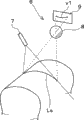
Figure 1A is the skeleton diagram that the structure of the surface of tyre shape measuring apparatus that adopts embodiments of the present invention is shown, and the state of the surface configuration of measuring little tire is shown;
Figure 1B is the skeleton diagram that the structure of the surface of tyre shape measuring apparatus that adopts embodiments of the present invention is shown, and the state of the surface configuration of measuring large tire is shown;
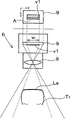
Fig. 2 is the schematic diagram that the three-dimensional configuration of linear light irradiation part in the sensor unit that the surface of tyre shape measuring apparatus possesses and filming apparatus is shown;
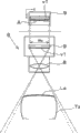
Fig. 3 A is the tread and the position relationship of shooting filming apparatus on shooting face and the figure of effective camera watch region that tire is shown, and the situation of little tire is shown;
Fig. 3 B is the tread and the position relationship of shooting filming apparatus on shooting face and the figure of effective camera watch region that tire is shown, and the situation of large tire is shown;
Fig. 4 is the situation of measuring the tread of little tire, and epimere means that light cuts off the schematic diagram of the relation of line and effective camera watch region, and hypomere means the figure that the brightness value in tread distributes;
Fig. 5 is the situation of measuring the tread of large tire, and epimere means that light cuts off the schematic diagram of the relation of line and effective camera watch region, and hypomere means the figure that the brightness value in tread distributes.
Embodiment
Below, with reference to accompanying drawing, embodiments of the present invention are described.
At first, the structure of the surface of tyre shape measuring apparatus 1 that adopts embodiments of the present invention is described with reference to Fig. 1.
Tire shape testing fixture 1 utilizes 6 pairs of shooting filming apparatus to pass through to the tire T(tire T of rotation
1and tire T
2) the linear light of surface irradiation and the light that forms cuts off line Ls and is made a video recording, and by based on this photographed images, being adopted the SHAPE DETECTION of light cross-section method to measure the height of each one of tire T.And tire shape testing fixture 1 is corresponding respectively brightness value by the height conversion of measured each one of tire T, obtain the two dimensional image (check image) on tire T surface.
As shown in Figure 1A and Figure 1B, surface of tyre shape measuring apparatus 1 possesses tire rotation machine 2, sensor unit 3, scrambler 4 and image processing apparatus 5.Figure 1A and Figure 1B illustrate identical surface of tyre shape measuring apparatus 1, are the tire T difference as determination object.Measuring undersized tire T shown in Figure 1A respectively
1state, measuring large-sized tire T shown in Figure 1B
2state.
In the present embodiment, possess the sensor unit 3a for the SHAPE DETECTION of the tread of tire T, and for 2 sensor unit 3b and the 3c of the SHAPE DETECTION of 2 side wall surfaces.Sensor unit 3a is arranged to tread opposed, and sensor unit 3b and 3c are arranged to side wall surface opposed.
Linear light irradiation part 7 and shooting filming apparatus 6 to the sensor unit 3 of packing in the time of with reference to Fig. 2 describe.
Linear light irradiation part 7 possesses the line source of the linear light that irradiates sheet.Line source is by forming such as LED or Halogen lamp LED etc.The linear light of the sheet that utilization is irradiated from this linear light irradiation part 7, form 1 light on the surface of tire T and cut off line Ls.
As shown in Figure 2, shooting filming apparatus 6 cuts off being made a video recording as v1 of line Ls by the light of projection on the shooting face at imaging apparatus 9, obtains the photographed images that light cuts off line Ls.
Getting back to Fig. 1 describes scrambler 4.The scrambler 4 of being located at tire rotation machine 2 is anglecs of rotation of detecting the turning axle of tire rotation machine 2, is the anglec of rotation of tire T, and the sensor using the anglec of rotation that detects as detection signal output.The shooting of the shooting filming apparatus 6 that this detection signal possesses for sensor unit 3 control regularly.
For example, during the image processing apparatus 5 described later angle set in the every rotation of tire T of the speed with 60 rpm rotation, reception is from the detection signal of scrambler 4 outputs, and the mode of regularly being made a video recording with the reception that coordinates detection signal is controlled the shooting filming apparatus 6 of sensor unit 3.Thus, with the set pick-up rate (shooting frequency) regularly conformed to the reception of detection signal, made a video recording.
And, image processing apparatus 5 possesses SHAPE DETECTION parts 12, image that 12 pairs of SHAPE DETECTION parts are taken into is implemented binary conversion treatment etc. and is extracted light out and cut off line Ls, and cuts off from resulting light the height that line Ls obtains surface of tyre based on the triangulation ratio juris and distribute.
In addition, image processing apparatus 5 consists of the personal computer such as possessing frame memory etc., and camera watch region set parts 10 and pixel data are extracted parts 11 out, to the control part output order of the shooting filming apparatus 6 that is built in sensor unit 3, is controlled.
In the time of with reference to Fig. 3 A ~ Fig. 5, the camera watch region set parts 10 of explanation image processing apparatus 5, pixel data are extracted parts 11 out.
Camera watch region set parts 10 with the picture of the linear light that comprises whole surface imagings of the shooting at imaging apparatus 9, at the light of shooting face projection, cut off the mode of the picture v1 of line Ls, set effective camera watch region A on this shooting face.
Fig. 3 A is shown schematically in little tire T
1the light that forms of tread cut off the corresponding relation that line Ls and the light of projection on the shooting face of imaging apparatus 9 cut off the picture v1 of line Ls.Fig. 3 B is shown schematically in large tire T
2the light that forms of the tread corresponding relation that cuts off line Ls and picture v1 on shooting face.
In Fig. 3 A and Fig. 3 B, each of the camera distance (operating distance) of the tread from camera lens 8 to tire T is roughly the same.Yet, during the varying in size of known tire T, light cuts off the length difference of line Ls, and then the length of the picture v1 on shooting face is also different.
For example, according to Fig. 3 A, Fig. 3 B, Fig. 4, in the little situation of tire, light cuts off line Ls and shortens, on shooting face as the v1 (width W that also shortens
1).According to Fig. 3 A, Fig. 3 B, Fig. 5, contrary in the situation that tire is large, it is elongated that light cuts off line Ls, and the picture v1 on shooting face is elongated (width W also
2).
Camera watch region set parts 10 is the mode to comprise the picture v1 that whole length with tire T is different like this, sets the size effective camera watch region A corresponding with the length of picture v1 on shooting face.
As used as shown in oblique line on the top of Fig. 3 A and Fig. 3 B, effectively camera watch region A cuts off the set of the pixel that reality is used as v1 is made a video recording of line Ls for the light among shooting face, and setting for when facing the shooting face of imaging apparatus 9 is rectangle.For example, as shown in Fig. 3 A and Fig. 3 B, X coordinate by determining respectively the pixel in shooting face and the scope (scope of the address of pixel) of Y coordinate, the set of pixel that X coordinate and Y coordinate (address of pixel) is positioned to their scope is made as effective camera watch region A, thereby can set effective camera watch region A of rectangle that long edge the length direction of picture v1.
The upper and lower bound of the scope of this X coordinate, the X coordinate that is made as the two ends as v1 of light cut-out line Ls gets final product.In addition, determine as the upper limit of the scope of Y coordinate is fully larger than the maximal value of the Y coordinate as v1, the lower limit of the scope of Y coordinate is than abundant little the getting final product of the minimum value of the Y coordinate as v1.Thus, can set ordinatedly effective camera watch region A with the length as v1, can be reliably to being made a video recording as v1 in effective camera watch region A.
Pixel data is extracted parts 11 out and is taken out the pixel data (brightness data of pixel) that is present in the effective camera watch region A set by camera watch region set parts 10 from imaging apparatus 9.
For instance, in Fig. 4, in the situation that effectively camera watch region A is X * Y=1200 * 300 pixels, the control part that pixel data is extracted 11 pairs of shooting filming apparatus 6 of parts out sends indication, make from the pixel data in effective camera watch region A, along Y-axis for example every 3 pixels pass on the horizontal scanning data of 1 amount of pixels.And pixel data is extracted parts 11 out and is sent indication, for passed on horizontal scanning data, along X-axis for example every 2 pixels the pixel data of 1 amount of pixels is passed on to outside.That is, pixel data is extracted 11 couples of effective camera watch region A of parts out, as the sweep trace of predetermined both determined number, establishes the horizontal direction sweep trace and is 100, vertical scan direction line and be 600, and extract the pixel data as measured signal out from effective camera watch region A.
Utilize the pixel data of extracting out like this, can obtain the brightness value distribution that light cuts off the width W of line Ls that spreads all over as shown in the hypomere of Fig. 4.
Give one example again, in the situation that in Fig. 5, effective camera watch region A is X * Y=1800 * 400 pixels, the control part that pixel data is extracted 11 pairs of shooting filming apparatus 6 of parts out sends indication, make from the pixel data in effective camera watch region A, along Y-axis for example every 4 pixels pass on the horizontal scanning data of 1 amount of pixels.And pixel data is extracted parts 11 out and is sent indication, for passed on horizontal scanning data, along X-axis for example every 3 pixels the pixel data of 1 amount of pixels is passed on to outside.Thus, pixel data is extracted 11 couples of effective camera watch region A of parts out, and setting the horizontal direction sweep trace and be 100, vertical scan direction line is 600, extracts pixel data out.
By the extraction method vague generalization of above-mentioned pixel data, as described below.
Effectively camera watch region A is X * Y=P
x* P
ypixel, establishing as the horizontal direction number of scanning lines of extracting object out is that n bar, the same vertical scan direction line number as extracting object out are the m bar.
Now, the control part that pixel data is extracted 11 pairs of shooting filming apparatus 6 of parts out sends indication, from the pixel data in effective camera watch region A, along the every [P of Y-axis
y/ n] pixel passes on the horizontal scanning data of 1 amount of pixels.In addition, pixel data is extracted parts 11 out and is sent indication, for passed on horizontal scanning data, along the every [P of X-axis
x/ m] pixel passes on the pixel data of 1 amount of pixels to outside.
In addition, [P
y/ n] and [P
x/ m] be to P
y/ n and P
x/ m rounded up or cast out and round values.
Identical with Fig. 4, utilize the pixel data of extracting out like this, can obtain the width W that light cuts off line Ls that spreads all over as shown in the hypomere of Fig. 5
2brightness value distribute.
In other words, in the present embodiment, even effectively varying in size of camera watch region A, do not change the number (in above example being 100) of this horizontal direction sweep trace and the number (in above example being 600) of vertical scan direction line yet and be made as necessarily.That is, no matter be, measure little tire T
1the situation of tread still measure large tire T
2the situation of tread, all by the sweep trace number, be made as identical.Thereby, even different tire is installed on surface of tyre shape measuring apparatus 1 and is measured by the width of the thickness of side wall surface, tread, also can detect surface configuration with identical image resolution ratio and the high precision that adopts certain sweep trace number.
In addition, the number of this sweep trace (extraction number) determines the interior value of scope of the shooting frequency for realizing imaging apparatus 9.
Then, the image that 12 pairs of light of extracting the pixel data (brightness data) of parts 11 extractions out with pixel data and forming of the SHAPE DETECTION parts of image processing apparatus 5 cut off line Ls, application triangulation ratio juris, obtain light illuminated and cut off the height distributed intelligence of the part (1 line part on surface of tyre) of line Ls.
Surface of tyre shape measuring apparatus 1 with present embodiment of above-mentioned structure, even the different tire T(tire T of size
1and tire T
2), also can utilize camera watch region set parts 10 to set effective camera watch region A of suitable size, utilize pixel data to extract parts 11 out and extract the pixel data of photographed images from effective camera watch region A out.
In the time of with reference to Fig. 1, Fig. 4 and Fig. 5, the action of surface of tyre shape measuring apparatus 1 is described.
As mentioned above, surface of tyre shape measuring apparatus 1 possesses for tire T
1the sensor unit 3a of SHAPE DETECTION of tread, and for 2 sensor unit 3b and the 3c of the SHAPE DETECTION of 2 side wall surfaces.Sensor unit 3a is set as with tread opposed, and sensor unit 3b and 3c are set as with side wall surface opposed.Each sensor unit 3a, 3b, 3c possess to tire T
1the linear light irradiation part 7 of surface irradiation linear light, and at tire T
1the light of surface reflection cut off the shooting part 6 that the picture of line Ls is made a video recording.Can be and be connected to each other and at tire T from 3 linear lights of sensor unit 3a, 3b, 3c
1surface become a continuous linear light, also can become discontinuous linear light in addition.
The photographed images of the shooting part 6 in being provided to each sensor unit 3a, 3b, 3c is sent to respectively image processing apparatus 5.As described above, image processing apparatus 5 possesses camera watch region set parts 10 and pixel data is extracted parts 11 out, carries out the processing from the photographed images of sensor unit 3a, 3b, 3c.
In addition, can make sensor unit 3a, 3b, 3c work simultaneously, but its asynchronous working also the time.As described later, the shooting situation that can cut off line Ls according to light adopts any working method.
At first, with reference to Fig. 4 to measuring tire T
1tread the time action describe.
By tire T
1be installed on surface of tyre shape measuring apparatus 1 and start rotation, for example, while reaching set rotational speed (60 rpm), at first, the linear light irradiation part 7 of sensor unit 3a is to tire T
1tread irradiate linear light.The linear light irradiated is at tire T
1tread form light and cut off line Ls.6 pairs of formed light of shooting filming apparatus cut off line Ls and are made a video recording, and on the shooting face of imaging apparatus 9, imaging cuts off the picture v1 of line Ls.
Now, because light cuts off the dark of line Ls on every side, thereby, except light cuts off the picture v1 of line Ls, almost do not made a video recording.Therefore, only taken picture v1 in the image with 6 shootings of shooting filming apparatus, can think that made a video recording picture v1 former state ground directly reflects shape and the width of tread.
As shown in the epimere of Fig. 4, the camera watch region set parts 10 of image processing apparatus 5 is with will be as distance (width) W between the X coordinate at the two ends of v1
1be made as the mode of the length direction length on long limit, set effective camera watch region A(camera watch region of rectangle and set operation on the shooting face of imaging apparatus 9).
After the setting of effective camera watch region A, image processing apparatus 5 is only used effective camera watch region A of the shooting face of the imaging apparatus 9 in sensor unit 3a, spreads all over tire T
1all-roundly light cut off to line Ls made a video recording.
The tire T rotated with the speed of 60 rpm
1the set angle of every rotation, image processing apparatus 5 receives from the detection signal of scrambler 4 outputs.Coordinate the reception of detection signal regularly, image processing apparatus 5 is used 6 pairs of light of shooting filming apparatus of sensor unit 3a to cut off line Ls and is made a video recording.The set shooting frequency (for example 2kHz) of filming apparatus 6 regularly to conform to the reception of detection signal of making a video recording thus, spread all over tire T
1the all-round light that both allocations at tread are formed cut off line Ls and repeatedly make a video recording, the light that can obtain a plurality of imagings on the shooting face of imaging apparatus 9 cuts off the picture v1 of line Ls.
Then pixel data is extracted parts 11 out and is cut off the photographed images of line Ls from the light effectively camera watch region A makes a video recording, extraction and set number are (for example, article 600, the pixel data that sweep trace * l00 bar) is corresponding (measured signal of predetermined both determined number), transfer to frame memory (pixel data extraction operation).
When image processing apparatus 5 finishes the shooting of tread, make sensor unit 3b action, use the method same with the shooting of the tread that adopts sensor unit 3a, carry out tire T
1the shooting of side wall surface of top.By using the shooting of sensor unit 3b, spread all over tire T
1all-round, the light that both allocations of side wall surface are up formed cuts off line Ls and repeatedly makes a video recording, the light that can obtain a plurality of imagings on the shooting face of imaging apparatus 9 cuts off the picture v1 of line Ls.
If the shooting of the side wall surface of top finishes, image processing apparatus 5 makes sensor unit 3c action, with same method, carries out tire T
1the shooting of side wall surface of below.By using the shooting of sensor unit 3c, spread all over tire T
1all-round, to below the light that forms of both allocations of side wall surface cut off line Ls and repeatedly make a video recording, the light that can obtain a plurality of imagings on the shooting face of imaging apparatus 9 cuts off the picture v1 of line Ls.
Thereafter, SHAPE DETECTION parts 12 are respectively at tire T
1tread and two side walls, to by what extract with pixel data that parts 11 extract and transfer to a plurality of light cut-out line Ls that the pixel data (brightness data) of frame memory forms out, looking like v1 application triangulation ratio juris.To picture v1 application triangulation, can obtain the height distributed intelligence that illuminated each light cuts off the part (1 line part on surface of tyre) of line Ls.SHAPE DETECTION parts 12 are by tire T
1the all-round height distributed intelligence obtained as v1 from each be joined together, obtain tire T
1the side wall surface of tread, top and the two dimensional image (check image) of the side wall surface of below.
As mentioned above, tread, above side wall surface and below side wall surface, light cuts off line Ls and forms on 11 ground respectively.As long as at tire T
1all-round direction in the light that forms of each tire tread to cut off the position of line Ls identical,, on the shooting face shown in Fig. 4 and Fig. 5, the light that can form the tire tread in adjacency cuts off the end of line Ls and is made a video recording.In the situation that the light of adjacency is cut off to the end shooting of line Ls, switch as mentioned above sensor unit 3a ~ sensor unit 3c and to tire T
1made a video recording.
If the light of adjacency is not cut off the end shooting of line Ls, can make sensor unit 3a ~ sensor unit 3c move simultaneously.
In addition, each light cut-out line L5 need to be at tire T
1all-round direction in same position form, also can be at tire T
1all-round direction in be formed at diverse location.
Then, with reference to Fig. 5 to measuring than tire T
1the tire T that size is little
2the time action describe.
Tire T shown in Fig. 5
2assay method with to tire T
1assay method identical.Image processing apparatus 5 switches sensor unit 3a ~ sensor unit 3c successively, at tire T
2the light that forms of the side wall surface of tread, top and below cut off being made a video recording as v1 of line Ls.
Camera watch region set parts 10 with set ordinatedly and compare width W as v1
1short width W
2effective camera watch region A, pixel data is extracted parts 11 out and is cut off the photographed images of line Ls from the light effectively camera watch region A makes a video recording, extraction and set number are (for example, article 600, the pixel data that sweep trace * l00 bar) is corresponding (measured signal of predetermined both determined number), transfer to frame memory.Afterwards, use with for tire T
1the same method of assay method obtain tire T
2the two dimensional image (check image) of side wall surface of tread, top and below.
As mentioned above, if use the surface of tyre shape measuring apparatus 1 according to present embodiment, even as tire T
1with tire T
2like that, as the size difference of the tire T of determination object, with the length as v1 on shooting face, set ordinatedly effective camera watch region A, also can cut off being made a video recording as v1 of line Ls to light.
And, no matter the length on the long limit of the effective camera watch region A set (as the length of v1) how, is extracted the pixel data corresponding with the sweep trace of set number out, even thereby the size of tire T change, also can obtain with stable high resolving power tire T
2check image, can detect tire T
2surface configuration.
In addition, in institute, a little should to be considered as be all illustration and nonrestrictive to this disclosed embodiment.Particularly, in this disclosed embodiment, clearly not disclosed item, for example operation condition or condition determination, various parameters, the size of construct, weight, volume etc., do not break away from the scope that those skilled in the art implement usually, adopts so long as the value that those of ordinary skills just can easily suppose.
For example, in embodiments of the present invention, at first, set effective camera watch region A on the shooting face of imaging apparatus 9, the pixel data that will cut off from the light effectively camera watch region A makes a video recording the photographed images extraction of line Ls transfers to frame memory.Yet, be not limited to this, also can be before the setting of effective camera watch region A, the whole of photographed images that will make a video recording with imaging apparatus 9 transfer on frame memory., also can in the photographed images of depositing in frame memory set effective camera watch region A, extract pixel data out thereafter.
Description of reference numerals
1 surface of tyre shape measuring apparatus; 2 tire rotation machines; 3 sensor units; 4 scramblers; 5 image processing apparatus; 6 shooting filming apparatus; 7 linear light irradiation parts; 8 camera lens; 9 imaging apparatuss; 10 camera watch region set parts; 11 pixel datas are extracted parts out; 12 SHAPE DETECTION parts; The effective camera watch region of A; Ls light cuts off line; The T tire; The v1 picture.
Claims (according to the modification of the 19th of treaty)
1. a surface of tyre shape measuring apparatus, linear light to the surface that exposes to tire is made a video recording, and the measured signal of extracting out of the photographed images based on from this linear light measures the surface configuration of described tire, described surface of tyre shape measuring apparatus is characterised in that to possess:
Shooting part, be provided with the shooting face that the linear light on the surface to exposing to described tire is made a video recording;
The camera watch region set parts in the mode of the picture that comprises whole linear lights at described shooting surface imaging, is set effective camera watch region of the length direction length that possesses described linear light on described shooting face; And
Pixel data is extracted parts out, extracts the measured signal of predetermined both determined number out from effective camera watch region of described setting.
2. surface of tyre shape measuring apparatus as claimed in claim 1, is characterized in that,
Described camera watch region set parts is configured to described effective camera watch region is set on shooting face as rectangle, and will be made as along the distance between the two ends of the picture of described linear light the length on the long limit of described rectangle.
3. a surface of tyre process for measuring shape, the linear light that uses shooting to face the surface that exposes to tire is made a video recording, and the measured signal of extracting out of the photographed images based on from this linear light measures the surface configuration of described tire, described surface of tyre process for measuring shape is characterised in that to possess:
Camera watch region is set operation, in the mode that comprises whole linear lights at described shooting surface imaging, sets effective camera watch region of the length direction length that possesses linear light on described shooting face; And
Pixel data is extracted operation out, extracts the measured signal of predetermined both determined number out from effective camera watch region of described setting.
4. surface of tyre process for measuring shape as claimed in claim 3, is characterized in that,
Described camera watch region is set operation described effective camera watch region is set on shooting face as rectangle, and will be made as along the distance between the two ends of linear light the length on the long limit of described rectangle.
5. surface of tyre shape measuring apparatus as claimed in claim 2, is characterized in that,
The varying in size of described effective camera watch region even described pixel data is extracted parts out, the number that also makes the number of horizontal direction sweep trace and vertical scan direction line is extracted out from the pixel data in described effective camera watch region definitely.
6. surface of tyre process for measuring shape as claimed in claim 4, is characterized in that,
The varying in size of described effective camera watch region even described pixel data is extracted operation out, the number that also makes the number of horizontal direction sweep trace and vertical scan direction line is extracted out from the pixel data in described effective camera watch region definitely.
Claims (4)
1. a surface of tyre shape measuring apparatus, linear light to the surface that exposes to tire is made a video recording, and the measured signal of extracting out of the photographed images based on from this linear light measures the surface configuration of described tire, described surface of tyre shape measuring apparatus is characterised in that to possess:
Shooting part, be provided with the shooting face that the linear light on the surface to exposing to described tire is made a video recording;
The camera watch region set parts in the mode of the picture that comprises whole linear lights at described shooting surface imaging, is set effective camera watch region of the length direction length that possesses described linear light on described shooting face; And
Pixel data is extracted parts out, extracts the measured signal of predetermined both determined number out from effective camera watch region of described setting.
2. surface of tyre shape measuring apparatus as claimed in claim 1, is characterized in that,
Described camera watch region set parts is configured to described effective camera watch region is set on shooting face as rectangle, and will be made as along the distance between the two ends of the picture of described linear light the length on the long limit of described rectangle.
3. a surface of tyre process for measuring shape, the linear light that uses shooting to face the surface that exposes to tire is made a video recording, and the measured signal of extracting out of the photographed images based on from this linear light measures the surface configuration of described tire, described surface of tyre process for measuring shape is characterised in that to possess:
Camera watch region is set operation, in the mode that comprises whole linear lights at described shooting surface imaging, sets effective camera watch region of the length direction length that possesses linear light on described shooting face; And
Pixel data is extracted operation out, extracts the measured signal of predetermined both determined number out from effective camera watch region of described setting.
4. surface of tyre process for measuring shape as claimed in claim 3, is characterized in that,
Described camera watch region is set operation described effective camera watch region is set on shooting face as rectangle, and will be made as along the distance between the two ends of linear light the length on the long limit of described rectangle.
Applications Claiming Priority (3)
| Application Number | Priority Date | Filing Date | Title |
|---|---|---|---|
| JP2011094056A JP2012225795A (en) | 2011-04-20 | 2011-04-20 | Device and method for measuring tire surface shape |
| JP2011-094056 | 2011-04-20 | ||
| PCT/JP2012/060098 WO2012144430A1 (en) | 2011-04-20 | 2012-04-13 | Tire surface shape measuring device and tire surface shape measuring method |
Publications (1)
| Publication Number | Publication Date |
|---|---|
| CN103477183A true CN103477183A (en) | 2013-12-25 |
Family
ID=47041538
Family Applications (1)
| Application Number | Title | Priority Date | Filing Date |
|---|---|---|---|
| CN2012800190787A Pending CN103477183A (en) | 2011-04-20 | 2012-04-13 | Tire surface shape measuring device and tire surface shape measuring method |
Country Status (7)
| Country | Link |
|---|---|
| US (1) | US20140043472A1 (en) |
| EP (1) | EP2700903A4 (en) |
| JP (1) | JP2012225795A (en) |
| KR (1) | KR20130137682A (en) |
| CN (1) | CN103477183A (en) |
| TW (1) | TW201250201A (en) |
| WO (1) | WO2012144430A1 (en) |
Cited By (4)
| Publication number | Priority date | Publication date | Assignee | Title |
|---|---|---|---|---|
| CN106289097A (en) * | 2015-06-24 | 2017-01-04 | 住友橡胶工业株式会社 | Tire tread process for measuring shape and tire tread shape measuring apparatus |
| CN109269566A (en) * | 2018-10-22 | 2019-01-25 | 上海易清智觉自动化科技有限公司 | Tire detecting system |
| CN110398214A (en) * | 2019-08-01 | 2019-11-01 | 桂林梵玛科机械有限公司 | Carcass outer profile size method for fast measuring |
| CN110942444A (en) * | 2019-09-30 | 2020-03-31 | 阿里巴巴集团控股有限公司 | Object detection method and device |
Families Citing this family (11)
| Publication number | Priority date | Publication date | Assignee | Title |
|---|---|---|---|---|
| US9805697B1 (en) | 2012-06-01 | 2017-10-31 | Hunter Engineering Company | Method for tire tread depth modeling and image annotation |
| JP6155038B2 (en) * | 2013-02-08 | 2017-06-28 | リコーエレメックス株式会社 | Appearance inspection apparatus and appearance inspection method |
| US10063837B2 (en) * | 2013-07-25 | 2018-08-28 | TIREAUDIT.COM, Inc. | System and method for analysis of surface features |
| DE102014205515A1 (en) * | 2014-03-25 | 2015-10-01 | Robert Bosch Gmbh | Method and device for checking tire mounting on a vehicle |
| JP6265864B2 (en) * | 2014-08-12 | 2018-01-24 | 株式会社神戸製鋼所 | Tire testing equipment |
| KR101894683B1 (en) | 2015-05-29 | 2018-09-04 | 신닛테츠스미킨 카부시키카이샤 | Metal body shape inspection device and metal body shape inspection method |
| KR101956488B1 (en) | 2015-06-05 | 2019-03-08 | 신닛테츠스미킨 카부시키카이샤 | Apparatus for inspecting shape of metal body, and method for inspecting shape of metal body |
| US10789773B2 (en) | 2016-03-04 | 2020-09-29 | TIREAUDIT.COM, Inc. | Mesh registration system and method for diagnosing tread wear |
| US11472234B2 (en) | 2016-03-04 | 2022-10-18 | TIREAUDIT.COM, Inc. | Mesh registration system and method for diagnosing tread wear |
| KR101867175B1 (en) * | 2016-09-26 | 2018-06-12 | 금호타이어 주식회사 | Defect Detection Method and Same Apparatus for Half-finished Product of Tire |
| US11453259B2 (en) | 2018-02-01 | 2022-09-27 | Pixart Imaging Inc. | Object surface managing method and object surface managing system |
Citations (5)
| Publication number | Priority date | Publication date | Assignee | Title |
|---|---|---|---|---|
| EP1477765A1 (en) * | 2002-02-21 | 2004-11-17 | Kabushiki Kaisha Bridgestone | Method of detecting object of detection and device therefor, and method of inspecting object of inspection and device therefor |
| JP2005286241A (en) * | 2004-03-30 | 2005-10-13 | Fuji Mach Mfg Co Ltd | Operating machine associated with electronic circuit manufacturing |
| CN1997870A (en) * | 2004-06-03 | 2007-07-11 | 斯耐普昂公司 | Non-contact method and system for tyre analysis |
| JP2009041934A (en) * | 2007-08-06 | 2009-02-26 | Kobe Steel Ltd | Apparatus and method for shape measurement |
| JP2010156622A (en) * | 2008-12-27 | 2010-07-15 | Jfe Steel Corp | Shape measurement method and shape measurement apparatus of steel plate |
Family Cites Families (5)
| Publication number | Priority date | Publication date | Assignee | Title |
|---|---|---|---|---|
| JP3548465B2 (en) * | 1999-09-08 | 2004-07-28 | キヤノン株式会社 | Imaging device and imaging method |
| JP2001280917A (en) * | 2000-03-31 | 2001-10-10 | Minolta Co Ltd | Instrument for three-dimensional measurement |
| JP3759584B2 (en) * | 2001-11-30 | 2006-03-29 | 澁谷工業株式会社 | 3D height measurement method of objects |
| EP2172737B1 (en) * | 2007-08-06 | 2013-04-24 | Kabushiki Kaisha Kobe Seiko Sho | Tire shape measuring system |
| JP5191055B2 (en) * | 2009-02-20 | 2013-04-24 | パルステック工業株式会社 | Three-dimensional shape measuring apparatus and three-dimensional shape measuring method |
-
2011
- 2011-04-20 JP JP2011094056A patent/JP2012225795A/en active Pending
-
2012
- 2012-04-13 KR KR1020137027299A patent/KR20130137682A/en not_active Application Discontinuation
- 2012-04-13 EP EP12774229.4A patent/EP2700903A4/en not_active Withdrawn
- 2012-04-13 US US14/110,425 patent/US20140043472A1/en not_active Abandoned
- 2012-04-13 WO PCT/JP2012/060098 patent/WO2012144430A1/en active Application Filing
- 2012-04-13 CN CN2012800190787A patent/CN103477183A/en active Pending
- 2012-04-19 TW TW101113949A patent/TW201250201A/en unknown
Patent Citations (5)
| Publication number | Priority date | Publication date | Assignee | Title |
|---|---|---|---|---|
| EP1477765A1 (en) * | 2002-02-21 | 2004-11-17 | Kabushiki Kaisha Bridgestone | Method of detecting object of detection and device therefor, and method of inspecting object of inspection and device therefor |
| JP2005286241A (en) * | 2004-03-30 | 2005-10-13 | Fuji Mach Mfg Co Ltd | Operating machine associated with electronic circuit manufacturing |
| CN1997870A (en) * | 2004-06-03 | 2007-07-11 | 斯耐普昂公司 | Non-contact method and system for tyre analysis |
| JP2009041934A (en) * | 2007-08-06 | 2009-02-26 | Kobe Steel Ltd | Apparatus and method for shape measurement |
| JP2010156622A (en) * | 2008-12-27 | 2010-07-15 | Jfe Steel Corp | Shape measurement method and shape measurement apparatus of steel plate |
Cited By (6)
| Publication number | Priority date | Publication date | Assignee | Title |
|---|---|---|---|---|
| CN106289097A (en) * | 2015-06-24 | 2017-01-04 | 住友橡胶工业株式会社 | Tire tread process for measuring shape and tire tread shape measuring apparatus |
| CN106289097B (en) * | 2015-06-24 | 2020-04-21 | 住友橡胶工业株式会社 | Method and apparatus for measuring tire surface shape |
| CN109269566A (en) * | 2018-10-22 | 2019-01-25 | 上海易清智觉自动化科技有限公司 | Tire detecting system |
| CN110398214A (en) * | 2019-08-01 | 2019-11-01 | 桂林梵玛科机械有限公司 | Carcass outer profile size method for fast measuring |
| CN110942444A (en) * | 2019-09-30 | 2020-03-31 | 阿里巴巴集团控股有限公司 | Object detection method and device |
| CN110942444B (en) * | 2019-09-30 | 2023-05-02 | 阿里巴巴集团控股有限公司 | Object detection method and device |
Also Published As
| Publication number | Publication date |
|---|---|
| EP2700903A1 (en) | 2014-02-26 |
| US20140043472A1 (en) | 2014-02-13 |
| EP2700903A4 (en) | 2014-10-22 |
| JP2012225795A (en) | 2012-11-15 |
| WO2012144430A1 (en) | 2012-10-26 |
| KR20130137682A (en) | 2013-12-17 |
| TW201250201A (en) | 2012-12-16 |
Similar Documents
| Publication | Publication Date | Title |
|---|---|---|
| CN103477183A (en) | Tire surface shape measuring device and tire surface shape measuring method | |
| TWI448681B (en) | A method and an apparatus for simultaneous 2d and 3d optical inspection and acquisition of optical inspection data of an object | |
| CN109751973B (en) | Three-dimensional measuring device, three-dimensional measuring method, and storage medium | |
| JP2018179911A (en) | Range-finding device, distance information acquisition method | |
| CN106969706A (en) | Workpiece sensing and three-dimension measuring system and detection method based on binocular stereo vision | |
| CN104854427A (en) | Device for optically scanning and measuring environment | |
| US11073379B2 (en) | 3-D environment sensing by means of projector and camera modules | |
| CN101943572A (en) | Detect the method for measurement target | |
| US10841561B2 (en) | Apparatus and method for three-dimensional inspection | |
| WO2020065850A1 (en) | Three-dimensional measuring device | |
| CN103827626A (en) | Three-dimensional measurement device | |
| KR20230096057A (en) | Defect Layering Detection Method and System Based on Light Field Camera and Detection Production Line | |
| JP2003196656A (en) | Distance image processing device | |
| KR20100025001A (en) | Imaging device and method | |
| JP7119476B2 (en) | Tire contact shape analysis device and tire contact shape analysis method | |
| JP2002525561A (en) | Equipment for surface image detection and surface inspection of three-dimensional structures | |
| KR101622628B1 (en) | Method and apparatus of inspecting a substrate with electronic devices mounted thereon | |
| JP2016205963A (en) | Tire analysis device and tire analysis method | |
| US7777807B2 (en) | On-board object detector and on-board object detection method | |
| CN206583440U (en) | A kind of projected image sighting distance detecting system | |
| CN109660698A (en) | Image processing system and image treatment method | |
| CN114427835A (en) | Method and device for detecting center of lower supporting hole of mine under low illumination | |
| CN112710662A (en) | Generation method and device, generation system and storage medium | |
| JP2004226072A (en) | Shape measuring device | |
| JP2004094707A (en) | Method for estimating plane by stereo image and detector for object |
Legal Events
| Date | Code | Title | Description |
|---|---|---|---|
| C06 | Publication | ||
| PB01 | Publication | ||
| C10 | Entry into substantive examination | ||
| SE01 | Entry into force of request for substantive examination | ||
| C02 | Deemed withdrawal of patent application after publication (patent law 2001) | ||
| WD01 | Invention patent application deemed withdrawn after publication |
Application publication date: 20131225 |