CN103455196A - Information processing apparatus and method of manufacturing information processing apparatus - Google Patents
Information processing apparatus and method of manufacturing information processing apparatus Download PDFInfo
- Publication number
- CN103455196A CN103455196A CN2013101968941A CN201310196894A CN103455196A CN 103455196 A CN103455196 A CN 103455196A CN 2013101968941 A CN2013101968941 A CN 2013101968941A CN 201310196894 A CN201310196894 A CN 201310196894A CN 103455196 A CN103455196 A CN 103455196A
- Authority
- CN
- China
- Prior art keywords
- touch
- unit
- display
- screen
- zone
- Prior art date
- Legal status (The legal status is an assumption and is not a legal conclusion. Google has not performed a legal analysis and makes no representation as to the accuracy of the status listed.)
- Pending
Links
Images


Classifications
-
- G—PHYSICS
- G06—COMPUTING; CALCULATING OR COUNTING
- G06F—ELECTRIC DIGITAL DATA PROCESSING
- G06F3/00—Input arrangements for transferring data to be processed into a form capable of being handled by the computer; Output arrangements for transferring data from processing unit to output unit, e.g. interface arrangements
- G06F3/01—Input arrangements or combined input and output arrangements for interaction between user and computer
- G06F3/03—Arrangements for converting the position or the displacement of a member into a coded form
- G06F3/041—Digitisers, e.g. for touch screens or touch pads, characterised by the transducing means
- G06F3/044—Digitisers, e.g. for touch screens or touch pads, characterised by the transducing means by capacitive means
- G06F3/0446—Digitisers, e.g. for touch screens or touch pads, characterised by the transducing means by capacitive means using a grid-like structure of electrodes in at least two directions, e.g. using row and column electrodes
-
- G—PHYSICS
- G06—COMPUTING; CALCULATING OR COUNTING
- G06F—ELECTRIC DIGITAL DATA PROCESSING
- G06F3/00—Input arrangements for transferring data to be processed into a form capable of being handled by the computer; Output arrangements for transferring data from processing unit to output unit, e.g. interface arrangements
- G06F3/01—Input arrangements or combined input and output arrangements for interaction between user and computer
- G06F3/03—Arrangements for converting the position or the displacement of a member into a coded form
- G06F3/041—Digitisers, e.g. for touch screens or touch pads, characterised by the transducing means
- G06F3/0416—Control or interface arrangements specially adapted for digitisers
-
- G—PHYSICS
- G06—COMPUTING; CALCULATING OR COUNTING
- G06F—ELECTRIC DIGITAL DATA PROCESSING
- G06F3/00—Input arrangements for transferring data to be processed into a form capable of being handled by the computer; Output arrangements for transferring data from processing unit to output unit, e.g. interface arrangements
- G06F3/01—Input arrangements or combined input and output arrangements for interaction between user and computer
- G06F3/03—Arrangements for converting the position or the displacement of a member into a coded form
- G06F3/041—Digitisers, e.g. for touch screens or touch pads, characterised by the transducing means
- G06F3/044—Digitisers, e.g. for touch screens or touch pads, characterised by the transducing means by capacitive means
- G06F3/0445—Digitisers, e.g. for touch screens or touch pads, characterised by the transducing means by capacitive means using two or more layers of sensing electrodes, e.g. using two layers of electrodes separated by a dielectric layer
-
- G—PHYSICS
- G06—COMPUTING; CALCULATING OR COUNTING
- G06F—ELECTRIC DIGITAL DATA PROCESSING
- G06F2203/00—Indexing scheme relating to G06F3/00 - G06F3/048
- G06F2203/041—Indexing scheme relating to G06F3/041 - G06F3/045
- G06F2203/04103—Manufacturing, i.e. details related to manufacturing processes specially suited for touch sensitive devices
-
- Y—GENERAL TAGGING OF NEW TECHNOLOGICAL DEVELOPMENTS; GENERAL TAGGING OF CROSS-SECTIONAL TECHNOLOGIES SPANNING OVER SEVERAL SECTIONS OF THE IPC; TECHNICAL SUBJECTS COVERED BY FORMER USPC CROSS-REFERENCE ART COLLECTIONS [XRACs] AND DIGESTS
- Y10—TECHNICAL SUBJECTS COVERED BY FORMER USPC
- Y10T—TECHNICAL SUBJECTS COVERED BY FORMER US CLASSIFICATION
- Y10T29/00—Metal working
- Y10T29/49—Method of mechanical manufacture
- Y10T29/49002—Electrical device making
- Y10T29/49105—Switch making
Abstract
There is provided an information processing apparatus, including: a display unit including a display area, the display area being configured to display an image; and a touchscreen unit including a facing area and an outer area, the facing area facing the display area, the outer area being outside of the facing area. An area of the touchscreen unit is attached to the display unit, the area including the facing area and the outer area.
Description
Technical field
The disclosure relates to a kind of signal conditioning package of touch-screen display and method of manufacturing this signal conditioning package of comprising.
Background technology
Some signal conditioning packages such as PC comprise touch-screen display.Generally speaking, touch-screen display has following structure.Touch screen layer is stacked on display.Operation touch-screen (for example, seeing Japanese Patent Application Laid-Open 2008-176191) in the image that the user is showing on seeing described display.
Summary of the invention
People expect that the surface of the touch-screen display of the signal conditioning package that the user operates has higher intensity.Given this, general, the top surface of touch-screen display is glass cover.Yet, if the top surface of touch-screen display is glass cover, just increased the weight of signal conditioning package, and increased the thickness of touch-screen display.
In view of the foregoing, people's expectation provides a kind of weight gently and the less signal conditioning package of size.In addition, also expectation provides a kind of method of manufacturing such signal conditioning package.
According to the embodiment of present technique, it provides a kind of signal conditioning package that comprises display unit and touch screen unit.
Display unit comprises viewing area, and described viewing area is configured to show image.
Touch screen unit comprises faces zone (facing area) and perimeter (outer area), and the described area surface of facing is to described viewing area, and described perimeter is positioned at described in the face of outside zone.
One zone of described touch screen unit is attached to described display unit, and this zone comprises in the face of zone and perimeter.
According to this structure, can provide weight gently and the less signal conditioning package of size.
Described signal conditioning package may further include external unit, and this external unit holds described display unit and described touch screen unit, make described touch screen unit in the face of the zone and perimeter expose.
Described signal conditioning package may further include the back light unit of the surface that is arranged in described display unit, the surface that this surface opposite is attached in described touch screen unit.
Described back light unit can be arranged in a zone, this zone is roughly regional in the face of facing of described touch screen unit, and control panel can be arranged at least a portion zone on surface of described display unit, the surface that this surface opposite is attached in described touch screen unit, this zone does not comprise the zone that described back light unit is occupied.
Described control panel can be arranged in roughly in the face of in the zone of described perimeter.
According to the embodiment of present technique, provide a kind of method of manufacturing information treating apparatus.
Described method comprises: form the display unit that comprises a surface, this surface comprises viewing area and non-display area, and described viewing area is configured to show image, and described non-display area is positioned at the outside, described viewing area; With on the described surface of described display unit, electrode slice is set by means of roll laminating (roll lamination), predetermined electrode pattern is formed on described electrode slice, thereby forms touch screen unit on the described surface of described display unit.
According to this structure, the signal conditioning package that weight is light and size is less can be by being used simple method low cost fabrication.
As mentioned above, according to present technique, can provide weight gently and the less information processing of size.In addition, can provide the method for manufacturing such signal conditioning package.
The accompanying drawing explanation
These and other target of the present disclosure, feature and advantage will become more obvious with reference in the following detailed description of its most preferred embodiment shown in the drawings.
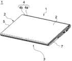
Figure 1A is the skeleton view shown according to the signal conditioning package of the first embodiment of present technique, and wherein signal conditioning package is opened;
Figure 1B is the skeleton view that shows the signal conditioning package of Figure 1A, and wherein signal conditioning package is closed;
The plan view of the touch-screen display of the signal conditioning package that Fig. 2 A is Figure 1A;
Fig. 2 B is the cut-open view of touch-screen display of Fig. 2 A of A-A' along the line intercepting;
Fig. 2 C is the cut-open view of touch-screen display of Fig. 2 A of B-B' along the line intercepting;
Fig. 3 is the process flow diagram of method that schematically shows the touch-screen display of shop drawings 2A, Fig. 2 B and Fig. 2 C;
Fig. 4 A is the plan view that shows the touch-screen display of a comparative examples;
The cut-open view of the touch-screen display of Fig. 4 A that Fig. 4 B is C-C' intercepting along the line;
The cut-open view of the touch-screen display of Fig. 4 A that Fig. 4 C is D-D' intercepting along the line;
Fig. 5 is the process flow diagram of method that schematically shows the touch-screen display of shop drawings 4A, Fig. 4 B and Fig. 4 C;
Fig. 6 A is the plan view according to the touch-screen display of the signal conditioning package of the second embodiment of present technique;
Fig. 6 B is the cut-open view of touch-screen display of Fig. 6 A of E-E' along the line intercepting;
Fig. 6 C is the cut-open view of touch-screen display of Fig. 6 A of F-F' along the line intercepting;
Fig. 7 A is the plan view according to the touch-screen display of the signal conditioning package of the 3rd embodiment of present technique;
Fig. 7 B is the cut-open view of touch-screen display of Fig. 7 A of G-G' along the line intercepting.
Fig. 7 C is the cut-open view of touch-screen display of Fig. 7 A of H-H' along the line intercepting.
Specific embodiment
Hereinafter with reference to accompanying drawing, embodiment of the present disclosure is described.
The first embodiment
[one-piece construction]
Figure 1A is the skeleton view shown according to the signal conditioning package of the first embodiment of present technique, and wherein signal conditioning package is opened.Figure 1B is the skeleton view that shows the signal conditioning package of Figure 1A, and wherein signal conditioning package is closed.This signal conditioning package 1 is the clamshell style PC.
This signal conditioning package 1 comprises the first external unit 2, the second external unit 3 and connection unit 4.Connection unit 4 connects described two external units 2 and 3.Each in the first external unit 2, the second external unit 3 and connection unit 4 made by the material that is not easy to distortion.The example of such material comprises, for example, such as the metal material of aluminium and such as the resin material of reinforced plastics.The first external unit 2, the second external unit 3 and connection unit 4 can be made by same material or different materials.
The viewing area 101 of touch-screen display 100 and non-display area 102 expose from the first external unit 2.The frame unit 2a of the first external unit 2 keeps the whole outer edge of non-display area 102.
When signal conditioning package 1 is opened, as shown in Figure 1A, touch-screen display 100 keeps erectting with respect to keyboard unit 8.When touch-screen display 100 is erect, the user can operate touch-screen display 100 and keyboard unit 8 when seeing touch-screen display 100.The user is with his finger or operate touch-screen display 100 such as the operating equipment of stylus (stylus).The user carrys out operation keyboard unit 8 with his finger.
Moment of torsion during connection unit 4 rotation arranges as follows.Even the user operates and presses touch-screen display 100, the first external units 2 with respect to the second external unit 3 rotations.In addition, user's opening/closing signal conditioning package 1 successfully.
When signal conditioning package 1 is closed, as shown in Figure 1B, touch-screen display 100 is in the face of keyboard unit 8.That is to say, the first external unit 2 covers touch-screen display 100, the second external unit 3 overlay keyboard unit 8.The signal conditioning package 1 that the user carries or keeping is closed.That is to say, when the user carries or takes care of signal conditioning package 1, touch-screen display 100 or keyboard unit can be not damaged.
[structure of touch-screen display]
Fig. 2 A is the plan view of touch-screen display 100.Fig. 2 B is the cut-open view of touch-screen display 100 of Fig. 2 A of A-A along the line intercepting.Fig. 2 C is the cut-open view of touch-screen display 100 of Fig. 2 A of B-B along the line intercepting.
X-axis, Y-axis and Z axis have been shown in each in Fig. 2 A, 2B and 2C.X-axis, Y-axis and Z axis are orthogonal.Fig. 2 A, 2B are identical with X-axis, Y-axis and Z axis in 2C.Note, the user operates touch-screen display 100 along Z-direction from upside.
In general, touch-screen display need to have a structure, and the user can skim over comfily by it on touch-screen display." skim over " the slide operation of its finger for the user on touch-screen display.It is below the example of skimming over.When use to wish changing the page of the file be presented on display unit, the user on touch-screen display, slide his finger just look like he really to climb over one page of book the same.As a result, the page of file is changed.
Given this, touch-screen display 100 has following structure.Non-display area 102 is arranged on the outside of viewing area 101.Non-display area 102 frame unit 2a expose.Non-display area 102 is spaced a predetermined distance from frame unit 2a.Viewing area 101 is concordant with non-display area 102.
Because this structure, when the user skims over 101 marginal portion, viewing area, the user is mobile its finger between viewing area 101 and non-display area 102 seamlessly.That is to say, when the user skims over touch-screen, his finger can not contact the frame unit.The user does not have unused sensation, because his finger can not be stuck in the frame unit.As a result, the user has obtained the operation sense of improving.Note, the width of the frame unit 2a of the first external unit 2 can be less.As a result, the distance between non-display area 102 and frame is larger.
Touch-screen display 100 comprises touch-screen 110, display panels 120 and back light unit 130.More specifically, touch-screen display 100 has following structure.Touch-screen 110, display panels 120 and back light unit 130 are stacked from upside along Z-direction.
Touch-screen 110 is sensor unit.Sensor unit receives user's operation.Display panels 120 and back light unit 130 are arranged in the rear side of touch-screen 110 along Z-direction.Display panels 120 and back light unit 130 are as display unit.This display unit produces and is presented at the image on viewing area 101.
Touch-screen 110 along the whole lower surface of Z-direction by using general translucent adhesive to be attached to display panels 120 along on the whole upper surface of Z-direction.
Further, metal frame 141 and resin frame 142 are installed to back light unit 130 on display panels 120.Metal frame 141 is made by the metal material such as aluminium, and has predetermined shape.Resin frame 142 is made by the resin material such as plastics, and has predetermined shape.
Touch-screen display 100 comprises control panel 126.Control panel 126 is controlled the touch screen unit that comprises touch-screen 110 and the display unit that comprises display panels 120 and back light unit 130.Control panel 126 is connected to the mainboard (not shown).The electronic unit such as CPU (Central Processing Unit) of signal conditioning package is arranged on mainboard.
[structure of touch-screen]
Touch-screen 110 comprises the first electrode slice 116 and the second electrode slice 114.The figure of the first electrode 116a is formed on the first electrode slice 116.The figure of the second electrode 114a is formed on the second electrode slice 114.Membrane type transparent flexible sheet is as the base material of each electrode slice 116,114.
On the first electrode slice 116, the first electrode 116a has following structure.A plurality of strip electrodes that extend along X-direction are arranged along Y direction.In addition, the second electrode 114a on the second electrode slice 114 has following structure.A plurality of strip electrodes that extend along Y direction are arranged along X-direction.The first electrode slice 116 and the second electrode slice 114 have formed the structure of cross matrix formula capacity cell.
First draws figure 116b draws from electrode 116a.First draws figure 116b is formed on the zone on the first electrode slice 116, and it is corresponding to non-display area 102.Similarly, second draw figure 114b and draw from electrode 114a.Second draws figure 114b is formed on the zone on the second electrode slice 114, and it is corresponding to non-display area 102.
Draw figure 116b and be connected to control panel 126 via flexible printed circuit board (PCB) 116c.Draw figure 114b and be connected to control panel 126 via flexible printed circuit board (PCB) 114c.Therefore, comprise the capacity cell of the first electrode slice 116 and the second electrode slice 114 can be to control panel 126 transmitted signals/reception the signal from control panel 126.
In addition, touch-screen 110 comprises screening glass 111.Screening glass 111 is outermost layer, and it receives user's operation.The structure of screening glass 111 is as follows.Hard coating, low reflection layer and the anti-layer that glitters are applied on PET (Polyethylene terephthalate) base material.The base material that any transparent material can be used as screening glass 111 substitutes PET.
In general, glass cover is attached on the outmost surface of touch-screen.Therefore, can the individual operation touch-screen, and can increase the surface strength of touch-screen.Simultaneously, as mentioned above, the touch-screen 110 of this embodiment does not comprise glass cover.The touch-screen 110 of this embodiment comprises the first electrode slice 116, the second electrode slice 114 and screening glass 111.The first electrode slice 116, the second electrode slice 114 and screening glass 111 are flexible sheets.
Therefore, touch-screen 110 is thinner and lightweight than general touch-screen.Yet, because touch-screen 110 is flexible, so be difficult to individual operation touch-screen 110.Therefore, can not individual operation touch-screen 110.Touch-screen 110 is pressed and states the method manufacture.
[structure of display panels]
Glass is as each the base material in color filter plate 122 and drive plate 124.Alternately, can use any materials with predetermined transparency and predetermined physical strength.The example of such base material comprises, for example acrylic acid and polycarbonate.
[structure of control panel and back light unit]
Back light unit 130 comprises optical prism sheet 132, optical scattering sheet 131, reflector plate 133 and LED (light emitting diode) unit 134.Optical scattering sheet 131 be arranged on optical prism sheet 132 along on the upper surface of Z-direction.Reflector plate 133 be arranged on optical prism sheet 132 along on the lower surface of Z-direction.LED unit 134 is along Y direction adjacent optical prismatic lens 132.
LED unit 134 comprises a plurality of LED on X-direction.LED unit 134 is luminous to optical prism sheet 132.Light enters in optical prism sheet 132, and light is superimposed in optical prism sheet 132, and thus, light is by homogenizing.In addition, light is reflected sheet 133 reflections, sees through optical scattering sheet 131 and enters display panels 120.
Control panel 126 is arranged on along the position of the contiguous back light unit 130 of Y direction.More specifically, control panel 126 is attached to the position of the rear side along Z-direction of display panels 120.This position is corresponding to non-display area 102, and back light unit 130 is not arranged in this position.Control panel 126 is attached via resin frame 142.
Control panel 126 is positioned at non-display area 102 inside along X-direction and Y direction.The surface, top side of control panel 126 is higher than the surface, the top side along Z-direction of back light unit 130.As mentioned above, the touch-screen display 100 of this embodiment has following structure.Control panel 126 is arranged in the space of contiguous back light unit 130.As a result, the size of whole touch-screen display 100 can be reduced.
According to this embodiment, control panel 126 is configured to control all touch-screens 110, display panels 120 and back light unit 130.Alternately, each in touch-screen 110, display panels 120 and back light unit 130 can have independent control module.In this case, except control panel 126, control module can be set.Control module can be arranged on being close in the space of back light unit 130 along X-direction of Fig. 2 B.
[manufacturing the method for touch-screen display]
Fig. 3 is the process flow diagram that schematically shows the method for manufacturing touch-screen display 100.The method of manufacturing touch-screen display 100 according to this, used roll laminating (roll lamination) energetically.Roll laminating is considered to low-cost and easily processing.Therefore, touch-screen display 100 can be with low cost fabrication.
In roll laminating, used the rolling sheet material.The rolling sheet material be will be combined a roll film material.At first, from a roll film material, pull out a slice, and this sheet cover will in conjunction with surface.Then, carry out squeegee roll extrusion (squeegee) processing make described closely attached will in conjunction with surface.Described is cut, thus the described size with surface that will be combined.Note, if described is not viscosity, so tack coat be arranged on described and will in conjunction with surface between.
According to this embodiment, the first polaroid 121,125 is attached to two surfaces of liquid-crystalline glasses box by roll laminating.The liquid-crystalline glasses box comprises color filter plate 122, liquid crystal layer 123 and drive plate 124.As a result, produce display panels 120.
The figure of the first electrode 116a is formed on slide, has manufactured thus the first electrode slice 116.The figure of the second electrode 114a is formed on slide, has manufactured thus the second electrode slice 114.The first electrode slice 116 is attached to display panels 120 by means of the roll laminating means via tack coat 117.Then, the second electrode slice 114 is attached to the first electrode slice 116 by means of the roll laminating means via tack coat 115.
Further, screening glass 111 is attached to the second electrode slice 114 by means of the roll laminating means via tack coat 113.Note, light shielding layer 112 is formed on screening glass 111 before.
As mentioned above, touch-screen 110 form display panels 120 along on the upper surface of Z-direction.According to the method for this embodiment, flexible touch-screen 110 can be formed on display panels 120, and flexible touch-screen 110 does not handle individually and the form of touch-screen 110 is constant.
Then, back light unit 130 and control panel 126 are by being used metal frame 141 and resin frame 142 to be installed on display panels 120.Then, flexible printed circuit board (PCB) 127,116c, 114c is attached.Note, back light unit 130, control panel 126 and flexible printed circuit board (PCB) 127 can be mounted before manufacturing touch-screen 110.
[comparative examples]
Fig. 4 A is the plan view shown according to the touch-screen display 200 of the comparative examples of this embodiment.The cut-open view of the touch-screen display 200 of Fig. 4 A that Fig. 4 B is C-C ' intercepting along the line.The cut-open view of the touch-screen display 200 of Fig. 4 A that Fig. 4 C is D-D ' intercepting along the line.Touch-screen display 200 has the structure of the structure of the touch-screen display 100 that is similar to this embodiment, except following structure.
Touch-screen 210 and display panels 220 are manufactured individually.Afterwards, touch-screen 210 is attached to display panels 220 via tack coat 217.As a result, manufactured touch-screen display 200.Touch-screen 210 forms discrete component.Therefore, the touch-screen 210 as discrete component need to have higher physical strength.Given this, glass cover 218 is arranged between screening glass 211 and the second electrode slice 214.As a result, even individual operation touch-screen 210, the form of touch-screen 210 is also constant.
Note, in touch-screen display 200, the light shielding layer 212 of non-display area 202 is not arranged on screening glass 211, and be arranged on glass cover 218 along on the lower surface of Z-direction.
Because glass cover 218 is heavier, touch-screen 210 may be crooked.Touch-screen 210 has produced signal.When touch-screen 210 is crooked, this signal probably comprises noise.
The zone of touch-screen display 200 in the XY plane is larger, and touch-screen 210 bendings are larger.Particularly, if touch-screen display 200 is applied to the clamshell style PC, touch-screen 210 may be crooked.This is because the size of touch-screen display 200 is equal to or greater than 10 inches.
Given this, tack coat 217 need to have high rigidity, so that touch-screen 210 can be not crooked.Touch-screen 210 is attached to display panels 220 via tack coat 217.
Touch-screen 210 can use UV (ultraviolet) resin by means of UV settable cementitious or use the optics adhesive sheet by means of vacuum in conjunction with being attached to display panels 220.As a result, manufactured the tack coat 217 with higher stiffness.Yet each in two methods is special adhesive method, it needs time and cost.
Simultaneously, the touch-screen 110 of this embodiment does not comprise the heavier parts the same such as glass cover.Therefore, tack coat 117 does not need to have higher rigidity.Touch-screen 110 is attached to display panels 120 via tack coat 117.Therefore, touch-screen 110 can easily be attached to display panels 120 with lower cost by using general method.
Note, in touch-screen display 200, due to the cause of glass cover 218, the form of touch-screen 210 can be constant.Therefore, display panels 220 is not formed in the zone under the non-display area along Z-direction 202 of touch-screen 210.
Simultaneously, according to the touch-screen display 100 of this embodiment, display panels 120 is formed in whole viewing area 101 and whole non-display area 102.Therefore, compare the display panels 220 of touch-screen display 200, the display panels 120 of touch-screen display 100 is relatively large.
Because display panels 120 is larger, so increased the weight of touch-screen display 100.Yet, due to glass cover not being set, so reduced the weight of touch-screen display 100.The weight that is greater than increase of the weight reduced.Therefore, compare touch-screen display 200, the weight of touch-screen display 100 is relatively light.
If touch-screen display is applied to the clamshell style signal conditioning package and is used, touch-screen display is erect, as shown in Figure 1A.Therefore, if touch-screen display is heavier, especially, when the first external unit that holds touch-screen display is placed on the rear, rear surface of the second external unit, the first external unit can fall towards the rear surface side.
In addition, if touch-screen display is heavier, connection unit 4 may rotate because of the weight of touch-screen display.Given this, the moment of torsion of connection unit 4 should be larger, so that connection unit 4 can not rotate.As a result, user's opening/closing signal conditioning package is more difficult.
As mentioned above, especially at touch-screen display, be used for the situation of clamshell style signal conditioning package, the touch-screen display that weight is lighter is of great use.
In addition, according to the touch-screen display 200 of this comparative examples, control panel 226 is arranged under back light unit 230 along Z-direction.As a result, because be provided with control panel 226, control panel 226 has increased the thickness of touch-screen display 200 along the height of Z-direction.
Simultaneously, according to the touch-screen display 100 of this embodiment, as mentioned above, control panel 126 is arranged in the space of contiguous back light unit 130.As a result, the thickness of touch-screen display 100 can be less than the thickness of touch-screen display 200.
Fig. 5 is the process flow diagram shown according to the manufacture method of the touch-screen display 200 of described comparative examples.
At first, polaroid 221,225 is attached to two surfaces of liquid-crystalline glasses box by the roll laminating means.The liquid-crystalline glasses box comprises color filter plate 222, liquid crystal layer 223 and drive plate 224.As a result, produce display panels 220.
The figure of the first electrode 216a is formed on slide, has manufactured thus the first electrode slice 216.The figure of the second electrode 214a is formed on slide, has manufactured thus the second electrode slice 214.
Before screening glass 211 and light shielding layer 212, be formed on glass cover 218.The second electrode slice 214 is attached to glass cover 218 by means of the roll laminating means via tack coat 213.Then, the first electrode slice 216 is attached to the second electrode slice 214 by means of the roll laminating means via tack coat 215.
As mentioned above, the touch-screen 210 of touch-screen display 200 is manufactured to discrete component.This is different from the touch-screen 110 of this embodiment.
Then, touch-screen 210 use the UV resins by means of above mentioned UV settable cementitious or use the optics adhesive sheet by means of above mentioned vacuum in conjunction with being attached to display panels 220.
Then, back light unit 230 and control panel 226 are by being used metal frame 241 and resin frame 242 to be installed on display panels 220.Then, flexible printed circuit board (PCB) 227,216c, 214c is attached.
The second embodiment
Fig. 6 A is the plan view shown according to the touch-screen display 300 of the second embodiment of present technique.Fig. 6 B is the cut-open view of touch-screen display 300 of Fig. 6 A of E-E ' along the line intercepting.Fig. 6 C is the cut-open view of touch-screen display 300 of Fig. 6 A of F-F ' along the line intercepting.Touch-screen display 300 has the structure of the structure of the touch-screen display 100 that is similar to this embodiment, except following structure.
In touch-screen display 300, the first electrode 316a and first draws figure 316b and is formed directly into along Z-direction on the upper surface of color filter plate 322 of liquid-crystalline glasses box.In addition, screening glass 315 be formed on color filter plate 322 along on the upper surface of Z-direction.Screening glass 315 covers the first electrode 316a and first and draws figure 316b.The second electrode 314a and second draws figure 314b and is formed on the upper surface of screening glass 315 along Z-direction.
In addition, screening glass 314 is formed on the upper surface of screening glass 315 along Z-direction.Screening glass 314 covers the second electrode 314a and second and draws figure 314b.Polaroid 321 is formed on the upper surface of screening glass 314 along Z-direction.
As mentioned above, can form (on-cell) first electrode 316a on the box of touch-screen 310.In this case, display panels 320 comprises liquid-crystalline glasses box and polaroid 325,321.The liquid-crystalline glasses box comprises color filter plate 322, liquid crystal layer 323 and drive plate 324.As mentioned above, electrode 316a, the 314a of touch-screen 310 can be formed on the upper surface of liquid-crystalline glasses box of display panels 320 along Z-direction.
Note, according to this embodiment, the box top electrode is formed on the liquid-crystalline glasses box along on the upper surface of Z-direction.Alternately, similar the first embodiment, the first electrode slice and the second electrode slice can be attached to the upper surface of liquid-crystalline glasses box along Z-direction by means of the roll laminating means.In this case, the polaroid of display panels can be attached to the upper surface of the second electrode slice along Z-direction by means of roll laminating.
The 3rd embodiment
Fig. 7 A is the plan view shown according to the touch-screen display 400 of the 3rd embodiment of present technique.Fig. 7 B is the cut-open view of this touch-screen display 400 of Fig. 7 A of G-G ' along the line intercepting.Fig. 7 C is the cut-open view of this touch-screen display 400 of Fig. 7 A of H-H ' along the line intercepting.Touch-screen display 400 has the structure of the structure of the touch-screen display 100 that is similar to this embodiment, except following structure.
In touch-screen display 400, display panels 420 is arranged on the slightly below, zone in the outside, 401He viewing area, viewing area 401.That is to say, display panels 420 is arranged on a part and 401 belows, viewing area of non-display area 402.More specifically, in touch-screen display 400, display panels 420 is the fixing major part of the lower surface of the touch-screen along Z-direction 410 in non-display area 402 not.This is different from the touch-screen display 100 of the first embodiment.
Alternately, the structure of touch-screen display 400 is as follows.Zone as the lower surface of the fixing touch-screen 410 along Z-direction of the resin frame 442 of fixed cell.This zone is not fixed on display panels 420.By such mode, the part of the lower surface of a fixing touch-screen 410 along Z-direction in display panels 420 and resin frame 442.Another is the other parts of the lower surface of touch-screen 410 fixedly.That is to say, display panels 420 and resin frame 442 be the whole lower surface of touch-screen 410 fixedly.As a result, touch-screen 410 is retained as flat.
In addition, the touch-screen 110 of the first embodiment comprises two electrode slices.Yet the touch-screen 410 of this embodiment comprises an electrode slice 414.The first electrode pattern 416a and first draws figure 416b and is formed on along on the lower surface of the electrode slice 414 of Z-direction.The second electrode pattern 414a and second draws figure 414b and is formed on along on the upper surface of the electrode slice 414 of Z-direction.
The number of electrode slice is not two but one.As a result, reduce part count, and simplified manufacturing process.As a result, can reduce the cost of touch-screen display 400.
The embodiment of present technique has below been described.Present technique is not limited to above-described embodiment.Certainly, can make various changes in the central idea of present technique.
For example, according to the embodiment of present technique, comprise that the liquid crystal display of display panels and back light unit is described as an example of display unit.Display unit can be other universal display unit.Note, display unit can be slim.The example of such display unit comprises, for example plasma display, organic EL (electroluminescence) display and inorganic EL display.
Note, present technique can adopt following structure.
(1) a kind of signal conditioning package comprises:
The display unit that comprises viewing area, described viewing area is configured to show image; With
Comprise the touch screen unit in the face of zone and perimeter, the described area surface of facing is to described viewing area, and described perimeter is positioned at described in the face of the outside, zone, wherein
One zone of described touch screen unit is attached to described display unit, and described zone comprises in the face of zone and perimeter.
(2) according to the signal conditioning package of (1), further comprise:
External unit, this external unit holds described display unit and described touch screen unit, make described touch screen unit in the face of the zone and perimeter expose.
(3) according to the signal conditioning package of (2), further comprise:
Be arranged in the back light unit of the surface of described display unit, the surface that this surface opposite is attached in described touch screen unit.
(4) signal conditioning package of basis (3), wherein
Described back light unit is arranged in a zone, and this zone is roughly regional in the face of facing of described touch screen unit, and
Control panel is arranged at least a portion zone on surface of described display unit, the surface that this surface opposite is attached in described touch screen unit, and this zone does not comprise the zone that described back light unit is occupied.
(5) signal conditioning package of basis (4), wherein
Described control panel is arranged in roughly in the face of in the zone of described perimeter.
(6) a kind of method of manufacturing information treating apparatus comprises:
Formation comprises the display unit on a surface, and this surface comprises viewing area and non-display area, and described viewing area is configured to show image, and described non-display area is positioned at the outside, described viewing area; With
On the described surface of described display unit, electrode slice is set by means of roll laminating, predetermined electrode pattern is formed on described electrode slice, thereby forms touch screen unit on the described surface of described display unit.
The disclosure comprises the relevant theme of disclosed content in the Japanese priority patent application JP2012-126594 submitted to Japan Office on June 1st, 2012, and the full content of this Jap.P. is incorporated herein by reference.
It will be appreciated by those skilled in the art that in claims or its and be equal in alternative scope, need and other factors according to design, can form various modification, combination, sub-portfolio and change.
Claims (6)
1. a signal conditioning package comprises:
The display unit that comprises viewing area, described viewing area is configured to show image; With
Comprise the touch screen unit in the face of zone and perimeter, the described area surface of facing is to described viewing area, and described perimeter is positioned at described in the face of the outside, zone, wherein
One zone of described touch screen unit is attached to described display unit, and described zone comprises in the face of zone and perimeter.
2. according to the signal conditioning package of claim 1, further comprise:
External unit, this external unit holds described display unit and described touch screen unit, make described touch screen unit in the face of the zone and perimeter expose.
3. according to the signal conditioning package of claim 2, further comprise:
Be arranged in the back light unit of the surface of described display unit, the surface that this surface opposite is attached in described touch screen unit.
4. according to the signal conditioning package of claim 3, wherein
Described back light unit is arranged in a zone, and this zone is roughly regional in the face of facing of described touch screen unit, and
Control panel is arranged at least a portion zone on surface of described display unit, the surface that this surface opposite is attached in described touch screen unit, and this zone does not comprise the zone that described back light unit is occupied.
5. according to the signal conditioning package of claim 4, wherein
Described control panel is arranged in roughly in the face of in the zone of described perimeter.
6. the method for a manufacturing information treating apparatus comprises:
Formation comprises the display unit on a surface, and this surface comprises viewing area and non-display area, and described viewing area is configured to show image, and described non-display area is positioned at the outside, described viewing area; With
On the described surface of described display unit, electrode slice is set by means of roll laminating, predetermined electrode pattern is formed on described electrode slice, thereby forms touch screen unit on the described surface of described display unit.
Applications Claiming Priority (2)
| Application Number | Priority Date | Filing Date | Title |
|---|---|---|---|
| JP2012-126594 | 2012-06-01 | ||
| JP2012126594A JP2013250900A (en) | 2012-06-01 | 2012-06-01 | Information processing apparatus and method of manufacturing the same |
Publications (1)
| Publication Number | Publication Date |
|---|---|
| CN103455196A true CN103455196A (en) | 2013-12-18 |
Family
ID=49669602
Family Applications (1)
| Application Number | Title | Priority Date | Filing Date |
|---|---|---|---|
| CN2013101968941A Pending CN103455196A (en) | 2012-06-01 | 2013-05-24 | Information processing apparatus and method of manufacturing information processing apparatus |
Country Status (3)
| Country | Link |
|---|---|
| US (5) | US9256308B2 (en) |
| JP (1) | JP2013250900A (en) |
| CN (1) | CN103455196A (en) |
Families Citing this family (5)
| Publication number | Priority date | Publication date | Assignee | Title |
|---|---|---|---|---|
| JP2013250900A (en) * | 2012-06-01 | 2013-12-12 | Sony Corp | Information processing apparatus and method of manufacturing the same |
| US9995956B2 (en) * | 2015-03-20 | 2018-06-12 | Opton (Shunchang) Optics Co., Ltd | Integrated fully-sealed liquid cryatal screen and manufacturing process for same |
| US9917266B2 (en) * | 2015-08-17 | 2018-03-13 | Microsoft Technology Licensing, Llc | Bendable device with a window top layer and a body having extendable bending region |
| CN105446565B (en) * | 2015-11-13 | 2018-03-06 | 业成光电(深圳)有限公司 | Rim area narrows formula contact panel and its touch control display apparatus |
| JP7071234B2 (en) * | 2018-06-29 | 2022-05-18 | キヤノン株式会社 | Electronics |
Citations (8)
| Publication number | Priority date | Publication date | Assignee | Title |
|---|---|---|---|---|
| JP2007079133A (en) * | 2005-09-14 | 2007-03-29 | Sharp Corp | Display module |
| US20100110033A1 (en) * | 2008-11-06 | 2010-05-06 | Epson Imaging Devices Corporation | Touch panel device, electro-optical device, and electronic apparatus |
| CN201600670U (en) * | 2009-12-22 | 2010-10-06 | 洋华光电股份有限公司 | Touch panel |
| CN201903870U (en) * | 2010-09-14 | 2011-07-20 | 升达科技股份有限公司 | Touch module |
| CN202189343U (en) * | 2011-08-08 | 2012-04-11 | 东莞联胜液晶显示器有限公司 | Touch control panel and the touch control display device |
| JP2012093985A (en) * | 2010-10-27 | 2012-05-17 | Nitto Denko Corp | Display panel device with touch input function, optical unit for display panel device and manufacturing method thereof |
| CN102467289A (en) * | 2010-10-29 | 2012-05-23 | 三星移动显示器株式会社 | Flat panel display with integrated touch screen panel |
| CN102478980A (en) * | 2010-11-23 | 2012-05-30 | 安浙触控科技有限公司 | Method for manufacturing human-machine interface device |
Family Cites Families (23)
| Publication number | Priority date | Publication date | Assignee | Title |
|---|---|---|---|---|
| TWI223116B (en) * | 2000-09-19 | 2004-11-01 | Au Optronics Corp | Liquid crystal display (LCD) device with a built-in touch panel and the manufacturing process thereof |
| KR100672646B1 (en) * | 2003-10-31 | 2007-01-23 | 엘지.필립스 엘시디 주식회사 | Liquid crystal display device which a touch panel was mounted on |
| US8243027B2 (en) * | 2006-06-09 | 2012-08-14 | Apple Inc. | Touch screen liquid crystal display |
| JP5358757B2 (en) | 2007-01-22 | 2013-12-04 | Nltテクノロジー株式会社 | Manufacturing method of liquid crystal display device |
| TWI439891B (en) * | 2007-09-29 | 2014-06-01 | Chunghwa Picture Tubes Ltd | Liquid crystal display with a built-in touch panel |
| JP5033078B2 (en) * | 2008-08-06 | 2012-09-26 | 株式会社ジャパンディスプレイイースト | Display device |
| JP4920646B2 (en) * | 2008-09-04 | 2012-04-18 | 株式会社 日立ディスプレイズ | Liquid crystal display |
| JP5308749B2 (en) * | 2008-09-05 | 2013-10-09 | 株式会社ジャパンディスプレイ | Liquid crystal display |
| TWI379226B (en) * | 2009-03-13 | 2012-12-11 | Tpk Touch Solutions Inc | Liquid crystal display with integrated capacitive touch device |
| KR20100112409A (en) * | 2009-04-09 | 2010-10-19 | 엘지전자 주식회사 | Display apparatus |
| WO2011070884A1 (en) * | 2009-12-08 | 2011-06-16 | シャープ株式会社 | Liquid crystal device |
| TWI407340B (en) * | 2009-12-22 | 2013-09-01 | Au Optronics Corp | Touch display panel |
| TW201124766A (en) * | 2010-01-08 | 2011-07-16 | Wintek Corp | Display device with touch panel |
| JP5278351B2 (en) * | 2010-02-26 | 2013-09-04 | カシオ計算機株式会社 | Display device with touch panel and antistatic structure |
| JP5433465B2 (en) * | 2010-03-16 | 2014-03-05 | 株式会社ジャパンディスプレイ | Display device |
| JP5370259B2 (en) | 2010-05-07 | 2013-12-18 | 富士通モバイルコミュニケーションズ株式会社 | Portable electronic devices |
| KR101319347B1 (en) * | 2010-06-10 | 2013-10-16 | 엘지디스플레이 주식회사 | Liquid Crystal Display Panel Associated with Touch Panel |
| US9360897B2 (en) * | 2010-09-29 | 2016-06-07 | Dai Nippon Printing Co., Ltd | Touchscreen panel sensor film and manufacturing method thereof |
| TW201243663A (en) * | 2011-04-20 | 2012-11-01 | Wintek Corp | Touch display panel |
| TWI448948B (en) * | 2011-06-14 | 2014-08-11 | Hannstar Display Corp | Touch display devices |
| KR101840220B1 (en) * | 2011-10-10 | 2018-03-21 | 삼성디스플레이 주식회사 | Method of driving a touch display panel and touch display apparatus for performing the same |
| TWM438792U (en) * | 2011-12-06 | 2012-10-01 | Guo-Cheng Huang | Improved structure for wrapper protector |
| JP2013250900A (en) * | 2012-06-01 | 2013-12-12 | Sony Corp | Information processing apparatus and method of manufacturing the same |
-
2012
- 2012-06-01 JP JP2012126594A patent/JP2013250900A/en active Pending
-
2013
- 2013-05-23 US US13/901,147 patent/US9256308B2/en active Active
- 2013-05-24 CN CN2013101968941A patent/CN103455196A/en active Pending
-
2016
- 2016-02-04 US US15/015,405 patent/US9710102B2/en active Active
-
2017
- 2017-06-20 US US15/627,538 patent/US9933894B2/en active Active
-
2018
- 2018-02-28 US US15/907,962 patent/US10228796B2/en active Active
-
2019
- 2019-01-22 US US16/253,514 patent/US11231823B2/en active Active
Patent Citations (9)
| Publication number | Priority date | Publication date | Assignee | Title |
|---|---|---|---|---|
| JP2007079133A (en) * | 2005-09-14 | 2007-03-29 | Sharp Corp | Display module |
| US20100110033A1 (en) * | 2008-11-06 | 2010-05-06 | Epson Imaging Devices Corporation | Touch panel device, electro-optical device, and electronic apparatus |
| CN201600670U (en) * | 2009-12-22 | 2010-10-06 | 洋华光电股份有限公司 | Touch panel |
| CN201903870U (en) * | 2010-09-14 | 2011-07-20 | 升达科技股份有限公司 | Touch module |
| JP2012093985A (en) * | 2010-10-27 | 2012-05-17 | Nitto Denko Corp | Display panel device with touch input function, optical unit for display panel device and manufacturing method thereof |
| CN103282862A (en) * | 2010-10-27 | 2013-09-04 | 日东电工株式会社 | Display panel device with touch input function, optical unit for said display panel device, and production method for same |
| CN102467289A (en) * | 2010-10-29 | 2012-05-23 | 三星移动显示器株式会社 | Flat panel display with integrated touch screen panel |
| CN102478980A (en) * | 2010-11-23 | 2012-05-30 | 安浙触控科技有限公司 | Method for manufacturing human-machine interface device |
| CN202189343U (en) * | 2011-08-08 | 2012-04-11 | 东莞联胜液晶显示器有限公司 | Touch control panel and the touch control display device |
Also Published As
| Publication number | Publication date |
|---|---|
| US9256308B2 (en) | 2016-02-09 |
| JP2013250900A (en) | 2013-12-12 |
| US9933894B2 (en) | 2018-04-03 |
| US20190155443A1 (en) | 2019-05-23 |
| US20130321311A1 (en) | 2013-12-05 |
| US10228796B2 (en) | 2019-03-12 |
| US20160154523A1 (en) | 2016-06-02 |
| US20180188886A1 (en) | 2018-07-05 |
| US20170285854A1 (en) | 2017-10-05 |
| US11231823B2 (en) | 2022-01-25 |
| US9710102B2 (en) | 2017-07-18 |
Similar Documents
| Publication | Publication Date | Title |
|---|---|---|
| JP5315064B2 (en) | Display device | |
| US9983455B2 (en) | Electronic device stack assembly | |
| JP5520093B2 (en) | Manufacturing method of touch panel | |
| JP5370944B2 (en) | Touch panel and manufacturing method thereof | |
| US20180072022A1 (en) | Curved stack structures, manufacturing methods thereof and curved electronic devices | |
| US9268165B2 (en) | Touch display device having optical clear resin | |
| US9395571B2 (en) | Touch display panel and touch display apparatus | |
| US11231823B2 (en) | Information processing apparatus and method of manufacturing information processing apparatus | |
| US20100245706A1 (en) | Liquid crystal display device | |
| US20100079698A1 (en) | Display device | |
| US9990064B2 (en) | Electronic device stack assembly | |
| JP2013130779A (en) | Display device | |
| TWM474189U (en) | Touch display apparatus | |
| US20140285734A1 (en) | Touch display apparatus | |
| JP2008181466A (en) | Display input device and display input system | |
| KR102214631B1 (en) | Display device having functional panel | |
| JP2013072980A (en) | Array type display device | |
| KR20200051898A (en) | Display device and mathod for fabricating the same | |
| US10036919B2 (en) | Monolithic diffuser plate, and backlight unit and liquid crystal display device using the same | |
| CN217739669U (en) | LCD panel, display module assembly and display device of integrated LENS | |
| TWI499949B (en) | Touch display panel and touch display apparatus | |
| US20240008344A1 (en) | Foldable display device | |
| JP4585226B2 (en) | Liquid crystal display | |
| KR20210055854A (en) | Display device | |
| KR20150104718A (en) | Liquid Crystal Display Device |
Legal Events
| Date | Code | Title | Description |
|---|---|---|---|
| C06 | Publication | ||
| PB01 | Publication | ||
| C10 | Entry into substantive examination | ||
| SE01 | Entry into force of request for substantive examination | ||
| RJ01 | Rejection of invention patent application after publication | ||
| RJ01 | Rejection of invention patent application after publication |
Application publication date: 20131218 |