CN103439670A - Alternating current power supply sensing device - Google Patents
Alternating current power supply sensing device Download PDFInfo
- Publication number
- CN103439670A CN103439670A CN2013103241950A CN201310324195A CN103439670A CN 103439670 A CN103439670 A CN 103439670A CN 2013103241950 A CN2013103241950 A CN 2013103241950A CN 201310324195 A CN201310324195 A CN 201310324195A CN 103439670 A CN103439670 A CN 103439670A
- Authority
- CN
- China
- Prior art keywords
- sensing apparatus
- power sensing
- coupled
- output terminal
- pin
- Prior art date
- Legal status (The legal status is an assumption and is not a legal conclusion. Google has not performed a legal analysis and makes no representation as to the accuracy of the status listed.)
- Pending
Links
Images


Abstract
The invention provides an alternating current power supply sensing device. In one embodiment, the alternating current power supply sensing device comprises an outer shell, a solenoid, a rectifier filter circuit and an amplification drive circuit. The outer shell comprises a through hole, a first output end and a second output end, and a wire loaded with an alternating current power supply can penetrate through the through hole. The solenoid is located inside the outer shell and surrounds the through hole, and a magnetic field generated by the alternating current power supply on the wire is sensed so as to generate first voltage. The rectifier filter circuit carries out rectification and filtering on the first voltage so as to generate second voltage. The amplification drive circuit amplifies the second voltage so as to generate output current between the first output end and the second output end.
Description
Technical field
Present invention is directed to AC power, particularly relevant for the sensing apparatus of AC power.
Background technology
Alternating current (Alternating Current, AC) refers to all electric currents of generating period variation of size and Orientation, and the operation mean value in one-period is zero.The direct current do not changed in time compared to direction, exchange the more efficient mode of electric system electric energy transmitting, and therefore commercial the and civilian electric power supply of various countries is all the mode that adopts alternating current at present.
Because most electric equipment is all with AC power supply electric energy, if AC power can't normal power supply, just electric equipment can't normal operation, easily cause the heavy losses of industrial processes.Therefore, whether normal power supply just becomes important topic to be solved to the detecting AC power.
The Patent Case that Fig. 8 is TaiWan, China patent announcement number No. M450732 provides a kind of block diagram of device for detecting voltage 800.Device for detecting voltage 800 receives the waveform signal of an external ac power source, and the amplitude of the waveform signal of external ac power source is compared with the amplitude of the waveform signal of a standby AC power.If external ac power source and the amplitude of standby AC power in identical time point.When if the amplitude of this external ac power source waveform is less than the amplitude of this standby AC power waveform, mean the lower voltage of this external ac power source and lower than the voltage rating of standby AC power.Now a control module is switched to a machinery and equipment state that is communicated in this standby AC power at once by the state that is communicated in external ac power source, cause by this situation of working as machine and shutting down of machinery and equipment with the voltage dip of avoiding external ac power source, to maintain the normal operation of machinery and equipment.
Yet current most sensing apparatus for AC power supply, must be coupled to AC power itself.As the prior art of Fig. 8, device for detecting voltage 800 must be coupled to external ac power source, and whether the voltage that could detect and compare the external communication electricity reduces.If sensing apparatus for AC power supply is coupled to AC power, just as the load that has increased AC power, can cause extra power consumption.
Summary of the invention
For the problem of above-mentioned existence, the invention provides a kind of AC power sensing apparatus.In an embodiment, this AC power sensing apparatus comprises a shell, a solenoid, a current rectifying and wave filtering circuit and an amplification driving circuit.This shell comprises that one is positioned at its Centromedian perforation, and this perforation can be held load has an electric wire of an AC power to pass wherein.This solenoid is positioned at this enclosure and around this perforation, the magnetic field that this AC power on this electric wire of sensing produces and produce one first voltage.This current rectifying and wave filtering circuit is positioned at this enclosure, and this first voltage is carried out to rectification and filtering with in producing a second voltage.This amplification driving circuit is positioned at this enclosure, amplifies this second voltage to produce an output current between one first output terminal and one second output terminal.
The invention provides a kind of AC power sensing apparatus.In an embodiment, this AC power sensing apparatus comprises a magnetic field induction circuit, a current rectifying and wave filtering circuit and an amplification driving circuit.One magnetic field of this magnetic field induction circuit inductance one specific region also produces one first voltage according to the intensity in this magnetic field in a first node, and a wire that wherein is loaded with an AC power produces this magnetic field in this specific region.This current rectifying and wave filtering circuit is coupled between this first node and a Section Point, and this first voltage is carried out to rectification and filtering in this Section Point, to produce a second voltage.This amplification driving circuit is coupled to this Section Point, amplifies this second voltage to produce an output current between one first output terminal and one second output terminal.
AC power sensing apparatus of the present invention is directly responded to the magnetic field that alternating current produces, and therefore without invasive, therefore can install easily this sensing apparatus additional on existing various device, without dismounting or destruction existing equipment.In addition, AC power sensing apparatus of the present invention utilizes electric power that magnetic field induction produces to light pilot lamp and without additional power source.In addition, AC power sensing apparatus of the present invention changes into digitized ON/OFF electronic signal by the AC signal of induction, and the interference-free distance of also can growing is detected.Finally, a plurality of AC power sensing apparatus of the present invention can be connected in series to save the input contact of programmable logical circuit (Programmable logic circuit, PLC) mutually.
The accompanying drawing explanation
Fig. 1 is the front schematic view according to AC power sensing apparatus of the present invention;
Fig. 2 A is the schematic perspective view according to AC power sensing apparatus of the present invention;
The schematic diagram in the magnetic field that the AC power of the perforation that Fig. 2 B is the AC power sensing apparatus central authorities that pass through produces;
Fig. 3 is the AC power sensing apparatus and the schematic diagram of wire with alternating current;
The schematic diagram of the corresponding relation of the electric current root-mean-square value of the output voltage that Fig. 4 is the AC power sensing apparatus and alternating current;
Fig. 5 is the block diagram according to AC power sensing apparatus of the present invention;
The schematic diagram that Fig. 6 A is the embodiment that is connected with the programmable logical circuit according to AC power sensing apparatus of the present invention;
The schematic diagram that Fig. 6 B is another embodiment of being connected with the programmable logical circuit according to AC power sensing apparatus of the present invention;
The schematic diagram that Fig. 7 is the embodiment that is connected with the programmable logical circuit according to a plurality of AC power sensing apparatus of the present invention;
The block diagram of a kind of device for detecting voltage that Patent Case provides that Fig. 8 is TaiWan, China patent announcement number No. M450732.
[symbol description]
100 ~ AC power sensing apparatus;
120 ~ pilot lamp;
110 ~ perforation;
130 ~ pin group;
130a, 130b, 130c, 130d ~ pin;
(Fig. 3)
300 ~ AC power sensing apparatus;
350 ~ with the wire of alternating current;
330a, 330b ~ pin;
(Fig. 5)
500 ~ AC power sensing apparatus;
560 ~ magnetic field induction circuit;
561 ~ solenoid;
570 ~ pilot lamp;
571 ~ LED light;
572 ~ resistance;
580 ~ current rectifying and wave filtering circuit;
581 ~ diode;
582 ~ electric capacity;
590 ~ amplification driving circuit;
591,592 ~ transistor;
593 ~ resistance;
(Fig. 6 A, Fig. 6 B, Fig. 7)
600,650,710,720 ..., 7n0 ~ AC power sensing apparatus;
640,690,700 ~ programmable logical circuit.
Embodiment
Below in conjunction with diagram and the embodiment of concrete operations, the invention will be further described.
Fig. 1 is the front schematic view according to an AC power sensing apparatus 100 of the present invention.The centre in the front of AC power sensing apparatus 100 has a perforation 110, bores a hole 110 can hold an electric wire through wherein, and on this electric wire, load has an AC power.In addition, the front of AC power sensing apparatus 100 also has a pilot lamp 120.It is accurate that AC power sensing apparatus 100 shows that by pilot lamp 120 amplitude of the AC power of load on electric wire whether reaches a normal position.If it is accurate that the amplitude of AC power reaches normal position, 120 of pilot lamp are shinny; Otherwise, if on electric wire not the amplitude of load alternating current source or AC power not reach normal position accurate, 120 of pilot lamp extinguish.Therefore, but the state of flickering of user's mat pilot lamp 120 is understood the amplitude of the AC power of load on electric wire whether that to reach normal position accurate.
In addition, the front of AC power sensing apparatus 100 also has a pin group 130.In an embodiment, pin group 130 comprises four pin 130a, 130b, 130c, 130d.Two output terminals that pin 130a and 130b are AC power sensing apparatus 100, that is AC power sensing apparatus 100 lies in the output current produced between this pin 130a and 130b.When the AC power of wiring load, to have a normal position accurate, and the output current system that AC power sensing apparatus 100 produces between pin 130a and 130b equals one first standard.On electric wire, the AC power of load alternating current source or wiring load is inaccurate lower than normal position, and the output current system that AC power sensing apparatus 100 produces between pin 130a and 130b equals a second standard.Therefore, but the size of the output current that user's mat AC power sensing apparatus 100 produces is understood the amplitude of the AC power of load on electric wire whether that to reach normal position accurate.
In an embodiment, pin group 130 more comprises pin 130c and 130d.Pin 130c is coupled to 130d, while contacting mutually for a plurality of AC power sensing apparatus of AC power sensing apparatus 100 and other.AC power sensing apparatus 100 will further illustrate in Fig. 7 with the mode that other a plurality of AC power sensing apparatus are contacted mutually.
Fig. 2 A is the schematic perspective view according to AC power sensing apparatus of the present invention.One electric wire is through the Centromedian perforation of AC power sensing apparatus.This electric wire does not couple mutually with the AC power sensing apparatus, so the AC power sensing apparatus can not become the load of AC power on electric wire, can not cause extra power consumption yet.On electric wire with alternating current Ip.Alternating current Ip on electric wire, along with the time changes the amplitude size, can induction produce a magnetic field around electric wire, and magnetic field intensity changes with the amplitude of alternating current Ip, as shown in Fig. 2 B.Therefore, the AC power sensing apparatus just can determine by the magnetic field around the induction central perforation position standard of the state that flickers and the output current of pilot lamp.
Fig. 3 is AC power sensing apparatus 300 and the schematic diagram of wire 350 with alternating current.The central authorities of AC power sensing apparatus 300 have a perforation 310.Wire 350 passes through with alternating current Ip and in perforation 310.Simultaneously, AC power sensing apparatus 300 has output terminal 330a and 330b.Produce between 330a and 330b and produce an output current in output terminal by the magnetic field of alternating current Ip generation around the 300 sensing perforation 310 of AC power sensing apparatus.In an embodiment, the pull-up resistor of output terminal is 2K Ω, and the electric current of flow through output terminal 330a and 330b is Ic, and the position standard of output current Ic is [24V-0.8V]/2K Ω.
The schematic diagram of the corresponding relation of the electric current root-mean-square value Ip of the output voltage V ce that Fig. 4 is the AC power sensing apparatus and alternating current.The output voltage V ce of AC power sensing apparatus has two position standards, and first standard is 0.8V, and the second standard is 24V.When the electric current root-mean-square value Ip of alternating current rises to 1A by 0A, the output voltage V ce of AC power sensing apparatus drops to first accurate 0.8V from the accurate 24V of second in period TPHL.When the electric current root-mean-square value Ip of alternating current drops to 0A by 1A, the output voltage V ce of AC power sensing apparatus rises to 75% level of the accurate 24V of second in period TPLH from first accurate 0.8V.Therefore, the user can judge by the position standard of output voltage V ce whether AC power Ip is positioned at normal position standard.
Fig. 5 is the block diagram according to AC power sensing apparatus 500 of the present invention.In an embodiment, AC power sensing apparatus 500 comprises a magnetic field induction circuit 560, a pilot lamp 570, a current rectifying and wave filtering circuit 580 and an amplification driving circuit 590.One magnetic field of the peripheral region of the central perforation of the shell of magnetic field induction circuit 560 induction AC power sensing apparatus 500 also produces one first voltages according to the intensity in this magnetic field in first node 551.In an embodiment, magnetic field induction circuit 560 comprises a solenoid (solenoid) 561, in order to sensing, is loaded with the magnetic field that a wire of an AC power produces in the peripheral region of this central perforation.Pilot lamp 570 is coupled between first node 551 and earth potential, luminous according to the intensity of the first voltage.In an embodiment, pilot lamp 570 comprises resistance 572 and a LED light 571.
Current rectifying and wave filtering circuit 580 is coupled between first node 551 and Section Point 552, and the first voltage is carried out to rectification and filtering in Section Point 552, to produce second voltages.In an embodiment, current rectifying and wave filtering circuit 580 comprises a diode 581 and an electric capacity 582.Diode 581 is coupled between first node 551 and Section Point 552, to the current commutates of flowing through between first node 551 and Section Point 552.Electric capacity 582 is coupled between Section Point 552 and earth potential.Amplification driving circuit 590 is coupled to Section Point 552, amplifies second voltage to produce an output current between the first output terminal 530a and the second output terminal 530b.In an embodiment, amplification driving circuit 590 comprises two transistor 591 and 592 and resistance 593.Resistance 593 is coupled between the base stage and Section Point 552 of transistor 591.Transistor 591 has a collector and is coupled to the first output terminal 530a.Transistor 592 has the emitter-base bandgap grading that a base stage is coupled to transistor 591, and a collector is coupled to the first output terminal 530a, and an emitter-base bandgap grading is coupled to the second output terminal 530b.
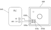
The schematic diagram that Fig. 6 A is the embodiment that is connected with programmable logical circuit 640 according to AC power sensing apparatus 600 of the present invention.The first output terminal 630a of AC power sensing apparatus 600 is coupled to the NPN I/P end points of programmable logical circuit 640, and the second output terminal 630b of AC power sensing apparatus 600 is coupled to the 0V end points of programmable logical circuit 640.The schematic diagram that Fig. 6 B is another embodiment of being connected with programmable logical circuit 690 according to AC power sensing apparatus 650 of the present invention.The first output terminal 680a of AC power sensing apparatus 650 is coupled to the 24V end points of programmable logical circuit 690, and the second output terminal 680b of AC power sensing apparatus 650 is coupled to the PNP I/P end points of programmable logical circuit 650.
Fig. 7 be according to a plurality of AC power sensing apparatus 710,720 of the present invention ..., the embodiment that is connected with programmable logical circuit 700 of 7n0 schematic diagram.During a plurality of AC power sensing apparatus series winding, except the AC power sensing apparatus of beginning and end, the coupling mode of AC power sensing apparatus that is positioned at stage casing is all identical.Take AC power sensing apparatus 720 as example.The second pin 720b of AC power sensing apparatus 720 is coupled to the first pin 710a of the AC power sensing apparatus 710 in the place ahead, and the 4th pin 720d of AC power sensing apparatus 720 is coupled to the 3rd pin 710c of the AC power sensing apparatus 710 in the place ahead.The first pin 720a of AC power sensing apparatus 720 is coupled to the second pin 730b of the AC power sensing apparatus 730 at rear, and the 3rd pin 720c of AC power sensing apparatus 720 is coupled to the 4th pin 730d of the AC power sensing apparatus 730 at rear.
In addition, the first pin 7n0a of the AC power sensing apparatus 7n0 of least significant end is coupled to the 3rd pin 7 (n-1) 0c of the AC power sensing apparatus 7 (n-1) 0 in the place ahead, and the second pin 7n0b of AC power sensing apparatus 7n0 is coupled to the first pin 7 (n-1) 0a of the AC power sensing apparatus 7 (n-1) 0 in the place ahead.The first pin 710a of AC power sensing apparatus 710 foremost is coupled to the com end points of the programmable logical circuit 700 in the place ahead, and the 4th pin 710d of AC power sensing apparatus 710 is coupled to the NPN I/P end points of programmable logical circuit 700.So; a plurality of AC power sensing apparatus 710,720 ..., 7n0 output voltage be connected across the second pin 710b and the 4th pin 710d two ends of the AC power sensing apparatus 710 of beginning by totalling, so programmable logical circuit 700 only must be coupled to the pin 710b of AC power sensing apparatus 710 of beginning and 710d two ends just can detect through a plurality of AC power sensing apparatus 710,720 ..., 7n0 a plurality of AC power wherein any one whether have the power supply undesired or the outage situation.
AC power sensing apparatus of the present invention is directly responded to the magnetic field that alternating current produces, and therefore without invasive, therefore can install easily this sensing apparatus additional on existing various device, without dismounting or destruction existing equipment.In addition, AC power sensing apparatus of the present invention utilizes electric power that magnetic field induction produces to light pilot lamp and without additional power source.In addition, AC power sensing apparatus of the present invention changes into digitized ON/OFF electronic signal by the AC signal of induction, and the interference-free distance of also can growing is detected.Finally, a plurality of AC power sensing apparatus of the present invention can be connected in series to save the input contact of programmable logical circuit mutually.
Claims (10)
1. an AC power sensing apparatus, have one first output terminal and one second output terminal, comprising:
One solenoid, respond to a magnetic field of a specific region and produce one first voltage according to the intensity in this magnetic field in a first node, and a wire that wherein is loaded with an AC power produces this magnetic field in this specific region;
One current rectifying and wave filtering circuit, be coupled between this first node and a Section Point, and this first voltage is carried out to rectification and filtering in this Section Point, to produce a second voltage; And
One amplification driving circuit, be coupled to this Section Point, amplifies this second voltage to produce an output current between this first output terminal and this second output terminal.
2. AC power sensing apparatus as claimed in claim 1, more comprise a pilot lamp, is coupled between this first node and an earth potential, luminous according to the intensity of this first voltage.
3. AC power sensing apparatus as claimed in claim 1, wherein this current rectifying and wave filtering circuit comprises:
One diode, be coupled between this first node and this Section Point, to a current commutates of flowing through between this first node and this Section Point; And
One electric capacity, be coupled between this Section Point and an earth potential.
4. AC power sensing apparatus as claimed in claim 1, wherein this amplification driving circuit comprises:
One the first transistor, have a collector and be coupled to this first output terminal;
One resistance, be coupled between the base stage and this Section Point of this first transistor; And
One transistor seconds, have the emitter-base bandgap grading that a base stage is coupled to this first transistor, and a collector is coupled to this first output terminal, and an emitter-base bandgap grading is coupled to this second output terminal.
5. AC power sensing apparatus as claimed in claim 1, wherein this AC power sensing apparatus inputs to a programmable logical circuit via this first output terminal and this second output terminal by this output current.
6. AC power sensing apparatus as claimed in claim 1, wherein a shell of this AC power sensing apparatus has more one first pin and one second pin, this first pin is coupled to this second pin, wherein when this AC power sensing apparatus is connected in series mutually with a front AC power sensing apparatus and a rear AC power sensing apparatus, this first output terminal of this AC power sensing apparatus is coupled to one second output terminal of this rear AC power sensing apparatus, this second output terminal of this AC power sensing apparatus is coupled to one first output terminal of this front AC power sensing apparatus, this first pin of this AC power sensing apparatus is coupled to one second pin of this rear AC power sensing apparatus, and this second pin of this AC power sensing apparatus is coupled to one first pin of this rear AC power sensing apparatus.
7. an AC power sensing apparatus comprises:
One shell, comprise a perforation, and this perforation can be held load has an electric wire of an AC power to pass wherein, and has one first output terminal and one second output terminal;
One solenoid, be positioned at this enclosure and around this perforation, the magnetic field that this AC power on this electric wire of sensing produces and produce one first voltage;
One current rectifying and wave filtering circuit, carry out rectification and filtering with in producing a second voltage to this first voltage; And
One amplification driving circuit, amplify this second voltage to produce an output current between this first output terminal and this second output terminal.
8. AC power sensing apparatus as claimed in claim 7, more comprise a pilot lamp, is coupled to this solenoid, luminous according to the intensity of this first voltage.
9. AC power sensing apparatus as claimed in claim 7, wherein this AC power sensing apparatus inputs to a programmable logical circuit via this first output terminal and this second output terminal by this output current.
10. AC power sensing apparatus as claimed in claim 7, wherein this shell has more one first pin and one second pin, this first pin is coupled to this second pin, wherein when this AC power sensing apparatus is connected in series mutually with a front AC power sensing apparatus and a rear AC power sensing apparatus, this first output terminal of this AC power sensing apparatus is coupled to one second output terminal of this rear AC power sensing apparatus, this second output terminal of this AC power sensing apparatus is coupled to one first output terminal of this front AC power sensing apparatus, this first pin of this AC power sensing apparatus is coupled to one second pin of this rear AC power sensing apparatus, and this second pin of this AC power sensing apparatus is coupled to one first pin of this rear AC power sensing apparatus.
Priority Applications (1)
| Application Number | Priority Date | Filing Date | Title |
|---|---|---|---|
| CN2013103241950A CN103439670A (en) | 2013-07-22 | 2013-07-22 | Alternating current power supply sensing device |
Applications Claiming Priority (1)
| Application Number | Priority Date | Filing Date | Title |
|---|---|---|---|
| CN2013103241950A CN103439670A (en) | 2013-07-22 | 2013-07-22 | Alternating current power supply sensing device |
Publications (1)
| Publication Number | Publication Date |
|---|---|
| CN103439670A true CN103439670A (en) | 2013-12-11 |
Family
ID=49693375
Family Applications (1)
| Application Number | Title | Priority Date | Filing Date |
|---|---|---|---|
| CN2013103241950A Pending CN103439670A (en) | 2013-07-22 | 2013-07-22 | Alternating current power supply sensing device |
Country Status (1)
| Country | Link |
|---|---|
| CN (1) | CN103439670A (en) |
Cited By (3)
| Publication number | Priority date | Publication date | Assignee | Title |
|---|---|---|---|---|
| CN104198956A (en) * | 2014-07-28 | 2014-12-10 | 凯立自动化有限公司 | Alternating-current power supply sensing device for automatically judging total number of elements to be detected and monitoring elements |
| CN108205085A (en) * | 2016-12-19 | 2018-06-26 | 旺玖科技股份有限公司 | To sense the sensor of electrical equipment use state and its method for sensing |
| US10601466B2 (en) | 2016-03-27 | 2020-03-24 | Prolific Technology Inc. | Sensor for sensing usage status of electrical device and associated method |
Citations (6)
| Publication number | Priority date | Publication date | Assignee | Title |
|---|---|---|---|---|
| JPS5590864A (en) * | 1978-12-29 | 1980-07-09 | Fujikura Ltd | Method of testing contact of multicore cable |
| CN2143017Y (en) * | 1993-02-17 | 1993-09-29 | 徐葆桢 | Low-voltage electrical leakage monitor for mine use |
| CN201449415U (en) * | 2009-07-13 | 2010-05-05 | 珠海市澳特尔测控仪表有限公司 | Alternating-current/direct-current leakage current sensor |
| US8299799B2 (en) * | 2000-02-17 | 2012-10-30 | Pass & Seymour, Inc. | Electrical device with miswire protection and automated testing |
| CN102998620A (en) * | 2012-12-17 | 2013-03-27 | 哈尔滨工业大学 | Device and method for quick online fault detection of high voltage thyristor valve block |
| TWM450732U (en) * | 2012-10-11 | 2013-04-11 | Prec Machinery Res & Dev Ct | Voltage detection transfer device |
-
2013
- 2013-07-22 CN CN2013103241950A patent/CN103439670A/en active Pending
Patent Citations (6)
| Publication number | Priority date | Publication date | Assignee | Title |
|---|---|---|---|---|
| JPS5590864A (en) * | 1978-12-29 | 1980-07-09 | Fujikura Ltd | Method of testing contact of multicore cable |
| CN2143017Y (en) * | 1993-02-17 | 1993-09-29 | 徐葆桢 | Low-voltage electrical leakage monitor for mine use |
| US8299799B2 (en) * | 2000-02-17 | 2012-10-30 | Pass & Seymour, Inc. | Electrical device with miswire protection and automated testing |
| CN201449415U (en) * | 2009-07-13 | 2010-05-05 | 珠海市澳特尔测控仪表有限公司 | Alternating-current/direct-current leakage current sensor |
| TWM450732U (en) * | 2012-10-11 | 2013-04-11 | Prec Machinery Res & Dev Ct | Voltage detection transfer device |
| CN102998620A (en) * | 2012-12-17 | 2013-03-27 | 哈尔滨工业大学 | Device and method for quick online fault detection of high voltage thyristor valve block |
Cited By (4)
| Publication number | Priority date | Publication date | Assignee | Title |
|---|---|---|---|---|
| CN104198956A (en) * | 2014-07-28 | 2014-12-10 | 凯立自动化有限公司 | Alternating-current power supply sensing device for automatically judging total number of elements to be detected and monitoring elements |
| CN104198956B (en) * | 2014-07-28 | 2017-04-12 | 宏荣国际股份有限公司 | Alternating-current power supply sensing device for automatically judging total number of elements to be detected and monitoring elements |
| US10601466B2 (en) | 2016-03-27 | 2020-03-24 | Prolific Technology Inc. | Sensor for sensing usage status of electrical device and associated method |
| CN108205085A (en) * | 2016-12-19 | 2018-06-26 | 旺玖科技股份有限公司 | To sense the sensor of electrical equipment use state and its method for sensing |
Similar Documents
| Publication | Publication Date | Title |
|---|---|---|
| CN105491730B (en) | A kind of LED lamp with USB interface string control system | |
| CN203101494U (en) | AC (alternating current) electric supply power failure detection circuit, equipment and system | |
| CN205080242U (en) | Power strip function test system | |
| CN104698262A (en) | Zero cross detection circuit and variable frequency air conditioner | |
| CN103439670A (en) | Alternating current power supply sensing device | |
| CN204945296U (en) | A kind of cellular phone data line tester | |
| CN205027852U (en) | Electric wire breakpoint detector | |
| CN102096109B (en) | Inductance type metal approach detecting probe | |
| CN206848624U (en) | Detection means | |
| CN103051206B (en) | Fresh-keeping device power control circuit, device and control method thereof | |
| CN214013869U (en) | Reliable single-phase wiring detection circuit of commercial power | |
| CN201387461Y (en) | Fault detector for circuit grounding | |
| CN102354886A (en) | Light-emitting cable displaying current transmission state | |
| CN201397385Y (en) | LED fluorescent tube detector | |
| CN202178480U (en) | Luminous cable capable of displaying current transmission state | |
| CN201332464Y (en) | Switch power supply circuit and television | |
| CN203587632U (en) | Switch device and cable identification device | |
| CN203130575U (en) | Alternating-current fan fault detecting circuit | |
| CN202145340U (en) | Capacitance bridge type human body approaching alarm | |
| CN203054119U (en) | Testing equipment for electronic component | |
| CN105954587B (en) | A kind of harmonics detection circuit and its detection method of distribution system | |
| CN110780238A (en) | Multi-core cable detection device | |
| CN205003216U (en) | Cable impedance detection circuitry | |
| CN204375087U (en) | Warning signal connector | |
| JP3192729U (en) | AC power detector |
Legal Events
| Date | Code | Title | Description |
|---|---|---|---|
| C06 | Publication | ||
| PB01 | Publication | ||
| C10 | Entry into substantive examination | ||
| SE01 | Entry into force of request for substantive examination | ||
| C02 | Deemed withdrawal of patent application after publication (patent law 2001) | ||
| WD01 | Invention patent application deemed withdrawn after publication |
Application publication date: 20131211 |