CN103411454A - A tubular heat exchanger with staggered arrangement of convex corrugated tubes - Google Patents
A tubular heat exchanger with staggered arrangement of convex corrugated tubes Download PDFInfo
- Publication number
- CN103411454A CN103411454A CN2013103850215A CN201310385021A CN103411454A CN 103411454 A CN103411454 A CN 103411454A CN 2013103850215 A CN2013103850215 A CN 2013103850215A CN 201310385021 A CN201310385021 A CN 201310385021A CN 103411454 A CN103411454 A CN 103411454A
- Authority
- CN
- China
- Prior art keywords
- type bellows
- raised type
- bellows tube
- tube
- heat exchanger
- Prior art date
- Legal status (The legal status is an assumption and is not a legal conclusion. Google has not performed a legal analysis and makes no representation as to the accuracy of the status listed.)
- Pending
Links
- 238000005192 partition Methods 0.000 abstract description 5
- 230000008646 thermal stress Effects 0.000 abstract description 4
- 239000012530 fluid Substances 0.000 description 15
- 238000012546 transfer Methods 0.000 description 12
- 238000010586 diagram Methods 0.000 description 9
- 230000008021 deposition Effects 0.000 description 5
- 239000012535 impurity Substances 0.000 description 5
- 238000011161 development Methods 0.000 description 4
- 230000007423 decrease Effects 0.000 description 2
- 238000000034 method Methods 0.000 description 2
- 230000003068 static effect Effects 0.000 description 2
- 238000005728 strengthening Methods 0.000 description 2
- 230000009286 beneficial effect Effects 0.000 description 1
- 238000013461 design Methods 0.000 description 1
- 238000001514 detection method Methods 0.000 description 1
- 230000000694 effects Effects 0.000 description 1
- 238000010438 heat treatment Methods 0.000 description 1
- 230000001737 promoting effect Effects 0.000 description 1
- 230000010349 pulsation Effects 0.000 description 1
- 238000005057 refrigeration Methods 0.000 description 1
- 239000012779 reinforcing material Substances 0.000 description 1
- 238000011160 research Methods 0.000 description 1
- 239000013535 sea water Substances 0.000 description 1
- 238000007789 sealing Methods 0.000 description 1
- 230000008016 vaporization Effects 0.000 description 1
- 238000009834 vaporization Methods 0.000 description 1
Images


Landscapes
- Heat-Exchange Devices With Radiators And Conduit Assemblies (AREA)
Abstract
一种外凸式波节管错位布置的管式换热器,它涉及一种波节管换热器,以解决现有的波节管换热器存在内部能量损耗大、热应力不均匀及易结垢的问题,它包括外壳、冷介质进口管、冷介质出口管、热介质进口管、热介质出口管、第一封头、第二封头、水平隔板、两个管板、多个折流板和多个换热管,多个换热管均为外凸式波节管,多个外凸式波节管按正三角形排列或正方形排列,且相邻两个外凸式波节管的圆弧凸起沿外凸式波节管的轴向相互错位。本发明用于热交换。

A tubular heat exchanger with staggered arrangement of convex corrugated tubes, which relates to a corrugated tube heat exchanger to solve the problems of large internal energy loss, uneven thermal stress and problems in existing corrugated tube heat exchangers The problem of easy fouling, which includes the shell, the cold medium inlet pipe, the cold medium outlet pipe, the heat medium inlet pipe, the heat medium outlet pipe, the first head, the second head, horizontal partitions, two tube plates, and more A baffle plate and a plurality of heat exchange tubes, the plurality of heat exchange tubes are convex corrugated tubes, the plurality of convex corrugated tubes are arranged in a regular triangle or square, and two adjacent convex corrugated tubes The arc protrusions of the joint pipe are misaligned with each other along the axial direction of the outwardly convex corrugated pipe. The invention is used for heat exchange.
Description
技术领域technical field
本发明涉及一种波节管换热器,具体涉及一种外凸式波节管错位布置的管式换热器,属于热交换工艺装备技术领域。The invention relates to a corrugated tube heat exchanger, in particular to a tubular heat exchanger with staggered arrangement of convex corrugated tubes, which belongs to the technical field of heat exchange process equipment.
背景技术Background technique
自70年代能源危机爆发以来,对传统换热器设备强化研究逐渐兴起,并主要集中在两大方向上;一是开发新的换热器品种,如板式、螺旋板式、振动盘管式、板翅式等等,这些换热器设计思想都是尽可能地提高换热效率;二是对传统的管壳式换热器采取强化措施。具体说来,就是用各种异型管取代原来的光管。现在较常用的有横槽纹管、缩放管、内翅管及管内插入强化物质等。Since the outbreak of the energy crisis in the 1970s, research on the strengthening of traditional heat exchanger equipment has gradually emerged, and mainly focused on two major directions; one is to develop new types of heat exchangers, such as plate type, spiral plate type, vibrating coil type, plate type, etc. The design idea of these heat exchangers is to improve the heat exchange efficiency as much as possible; the second is to take strengthening measures for the traditional shell-and-tube heat exchanger. Specifically, it is to replace the original light pipe with various special-shaped pipes. The more commonly used ones are horizontal grooved tubes, zoom tubes, inner finned tubes, and inserting reinforcing materials into the tubes.
波节管是一种特殊形状的缩放管,是以普通圆管为基管,通过液压成型的方式挤出一个个圆弧凸起,形成由弧形段和直管段交替变化组成的波节型通道。早在70年代,曾有人提出用波纹管作为换热管应用在管式换热器上,波节管是在1990年由中国的郎奎提出的,其强化换热的机理为:当流体在波纹管内流动时,波峰处流体速度降低、静压增加,波谷处流体速度增加、静压减少,这样,流体的流动在反复改变轴向上的压力梯度下进行,发生二次扰动,产生的剧烈涡旋冲刷了流体的边界层,使边界层减薄,破坏其边界层,并且提高管内外流体紊流的脉动性,促进湍流度的增加;另外直线段起着积累能量的作用,是不可缺少的,两者互相促进,大大提高了换热系数。因此,根据市场需要,这种高效换热管应用在很多行业中,例如:煤气站汽化、电厂首战、油田输油管道加热、储藏设备制冷、海水热交换等。The corrugated tube is a kind of zoom tube with a special shape. It is based on an ordinary circular tube and extruded with circular arc protrusions by hydroforming to form a corrugated node shape composed of alternating arc segments and straight tube segments. aisle. As early as the 1970s, it was proposed to use corrugated tubes as heat exchange tubes in tubular heat exchangers. The corrugated tubes were proposed by Lang Kui of China in 1990. The mechanism of its enhanced heat transfer is: when the fluid is in When flowing in the bellows, the fluid velocity decreases and the static pressure increases at the crest, and the fluid velocity increases and the static pressure decreases at the trough. In this way, the fluid flow proceeds under the pressure gradient in the axial direction repeatedly changing, and secondary disturbances occur, resulting in severe The vortex scours the boundary layer of the fluid, thins the boundary layer, destroys the boundary layer, and increases the pulsation of the fluid turbulence inside and outside the tube, promoting the increase of turbulence; in addition, the straight line plays the role of accumulating energy and is indispensable Yes, the two promote each other, greatly improving the heat transfer coefficient. Therefore, according to market needs, this high-efficiency heat exchange tube is used in many industries, such as gas station vaporization, power plant first battle, oil field oil pipeline heating, storage equipment refrigeration, seawater heat exchange, etc.
现有的波节管换热器中,各个波节管的波节与波节相对组成无错位波节管束,这样的确换热量较光管有所提升,但是各波节围成了突缩突扩的通道,流体在管间流动时每经过一个波距,就会节流一次,这不仅增加了摩擦阻力,而且增大了能量的损耗。同时由于仅在波节处大幅度提高换热效率,导致波节管各位置温度分布不均,进而产生热应力不匀等问题,而且在波节之间的直管段上由于流速较低又容易结垢,从而影响换热器的整体性能。In the existing corrugated tube heat exchanger, the nodes of each corrugated tube are opposite to each other to form a non-displaced corrugated tube bundle. In this way, the heat transfer rate is indeed improved compared with that of the bare tube, but each node is surrounded by a sudden shrinkage. In the suddenly expanded channel, when the fluid passes through a wave pitch when flowing between the tubes, the flow will be throttled once, which not only increases the frictional resistance, but also increases the energy loss. At the same time, because the heat transfer efficiency is greatly improved only at the corrugated nodes, the temperature distribution at each position of the corrugated tubes is uneven, which in turn causes problems such as uneven thermal stress. Fouling, thereby affecting the overall performance of the heat exchanger.
综上,现有的波节管换热器存在内部热量损耗大、热应力不均匀、易结垢的问题。To sum up, the existing corrugated tube heat exchangers have the problems of large internal heat loss, uneven thermal stress, and easy fouling.
发明内容Contents of the invention
本发明的目的是为解决现有的波节管换热器存在内部能量损耗大、热应力不均匀及易结垢的问题,进而提供一种外凸式波节管错位布置的管式换热器。The purpose of the present invention is to solve the problems of large internal energy loss, uneven thermal stress and easy fouling in existing corrugated tube heat exchangers, and to provide a tubular heat exchange with a dislocation arrangement of convex corrugated tubes device.
本发明为解决上述问题采取的技术方案是:本发明的一种外凸式波节管错位布置的管式换热器包括外壳、冷介质进口管、冷介质出口管、热介质进口管、热介质出口管、第一封头、第二封头、水平隔板、两个管板、多个折流板和多个换热管,外壳的两端内壁上各安装有一个管板,外壳的一侧端面上安装有第一封头,外壳的另一侧端面上安装有第二封头,外壳的顶部设置有热介质进口管,外壳的底部设置有热介质出口管,第一封头内设置有水平隔板,第一封头的顶部设置有冷介质进口管,第一封头的底部设置有冷介质出口管,外壳的内部沿竖向设置有多个折流板,多个换热管水平置于外壳内,多个换热管穿设在管板的管板孔内;多个换热管均为外凸式波节管,每个外凸式波节管上相邻两个圆弧凸起之间的距离为21mm-54mm,相邻两个外凸式波节管间距为24mm-39mm,多个外凸式波节管按正三角形排列或正方形排列,且相邻两个外凸式波节管的圆弧凸起沿外凸式波节管的轴向相互错位。The technical solution adopted by the present invention to solve the above problems is: a tubular heat exchanger with a dislocation arrangement of convex corrugated tubes of the present invention includes a shell, a cold medium inlet pipe, a cold medium outlet pipe, a heat medium inlet pipe, a heat exchanger Medium outlet pipe, first head, second head, horizontal partition, two tube sheets, multiple baffles and multiple heat exchange tubes, one tube sheet is installed on the inner wall of both ends of the shell, and the shell The first head is installed on one end surface, and the second head is installed on the other end surface of the shell. The top of the shell is provided with a heat medium inlet pipe, and the bottom of the shell is provided with a heat medium outlet pipe. There is a horizontal partition, the top of the first head is provided with a cold medium inlet pipe, the bottom of the first head is provided with a cold medium outlet pipe, the inside of the shell is vertically provided with multiple baffles, and multiple heat exchange The tubes are horizontally placed in the shell, and a plurality of heat exchange tubes are installed in the tube plate holes of the tube sheet; the plurality of heat exchange tubes are convex corrugated tubes, and each protruding corrugated tube is adjacent to two The distance between arc protrusions is 21mm-54mm, and the distance between two adjacent convex corrugated tubes is 24mm-39mm. Multiple convex corrugated tubes are arranged in a regular triangle or square, and two adjacent The arc protrusions of the convex corrugated tube are misaligned with each other along the axial direction of the convex corrugated tube.
本发明的有益效果是:The beneficial effects of the present invention are:
一、本发明的外凸式波节管换热器具有特殊的管束布置,多个外凸式波节管按正三角形排列或正方形排列,且相邻两个外凸式波节管的圆弧凸起沿外凸式波节管的轴向相互错位,减小流体流经圆弧凸起(波节)处得节流效应,消除圆弧凸起(波节)附近的流动死区,并且能够使流体流动平滑,减小流动阻力,内部热量损耗大大降低,使流体的流动均匀,波节管上温度分布均匀,圆弧凸起(波节)之间的直管段不易结垢。本发明的管式换热器内部能量损耗降低了10%-30%,提高了综合传热效率,综合传热效率提高了10%-20%。1. The protruding corrugated tube heat exchanger of the present invention has a special arrangement of tube bundles, a plurality of protruding corrugated tubes are arranged in a regular triangle or a square, and the arcs of two adjacent protruding corrugated tubes The protrusions are misaligned with each other along the axial direction of the convex corrugated tube, which reduces the throttling effect of the fluid flowing through the circular arc protrusions (wave nodes), eliminates the flow dead zone near the circular arc protrusions (wave nodes), and It can make the fluid flow smooth, reduce the flow resistance, greatly reduce the internal heat loss, make the fluid flow uniform, the temperature distribution on the corrugated pipe is uniform, and the straight pipe section between the arc protrusions (wave nodes) is not easy to scale. The internal energy loss of the tubular heat exchanger of the present invention is reduced by 10%-30%, and the comprehensive heat transfer efficiency is improved, and the comprehensive heat transfer efficiency is increased by 10%-20%.
二、本发明的波节管上相邻两个圆弧凸起之间的距离为21mm至54mm,既能保证换热量的增加,又能保证高危行业中在役检测的顺利进行。2. The distance between two adjacent arc protrusions on the corrugated tube of the present invention is 21mm to 54mm, which can not only ensure the increase of heat exchange, but also ensure the smooth progress of in-service detection in high-risk industries.
附图说明Description of drawings
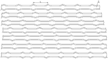
图1是本发明的整体结构主剖视图(图中箭头表示介质走向),图2是多个换热管按正三角形排列的示意图,图3是多个换热管按正方形排列的示意图,图4是正三角形排列的多个换热管的局部展开示意图,图5是具体实施方式二的正三角形排列的多个换热管的局部展开示意图,图6是具体实施方式三的正三角形排列的多个换热管的局部展开示意图,图7是具体实施方式四的正三角形排列的多个换热管的局部展开示意图,图8是具体实施方式五的正三角形排列的多个换热管的局部展开示意图,图9是具体实施方式六的正三角形排列的多个换热管的局部展开示意图。Fig. 1 is a main cross-sectional view of the overall structure of the present invention (the arrows in the figure indicate the direction of the medium), Fig. 2 is a schematic diagram of a plurality of heat exchange tubes arranged in an equilateral triangle, Fig. 3 is a schematic diagram of a plurality of heat exchange tubes arranged in a square, Fig. 4 Fig. 5 is a partially developed schematic diagram of multiple heat exchange tubes arranged in an equilateral triangle. Fig. 5 is a schematic diagram of partial development of a plurality of heat exchange tubes arranged in an equilateral triangle in Embodiment 2. Fig. 6 is a schematic diagram of a plurality of heat exchange tubes arranged in an equilateral triangle in
具体实施方式Detailed ways
具体实施方式一:结合图1-图4说明本实施方式,本实施方式的一种外凸式波节管错位布置的管式换热器包括外壳1、冷介质进口管2、冷介质出口管3、热介质进口管4、热介质出口管5、第一封头7、第二封头10、水平隔板11、两个管板6、多个折流板8和多个换热管9,外壳1的两端内壁上各安装有一个管板6,外壳1的一侧端面上安装有第一封头7,外壳1的另一侧端面上安装有第二封头10,外壳1的顶部设置有热介质进口管4,外壳1的底部设置有热介质出口管5,第一封头7内设置有水平隔板11,第一封头7的顶部设置有冷介质进口管2,第一封头7的底部设置有冷介质出口管3,外壳1的内部沿竖向设置有多个折流板8,多个换热管9水平置于外壳1内,多个换热管9穿设在管板6的管板孔内;多个换热管9均为外凸式波节管,每个外凸式波节管上相邻两个圆弧凸起之间的距离L为21mm-54mm,相邻两个外凸式波节管间距T为24mm-39mm,多个外凸式波节管按正三角形排列或正方形排列,且相邻两个外凸式波节管的圆弧凸起沿外凸式波节管的轴向相互错位。Specific embodiment 1: This embodiment is described in conjunction with Fig. 1-Fig. 4. A tubular heat exchanger with a convex corrugated tube arrangement in this embodiment includes a
本实施方式采用正方形排列的外凸式换热管,换热效率略有降低,但摩擦阻力也同样降低,在某些流量下,综合传热效率较同样的三角形排列管束有所增加。This embodiment adopts convex heat exchange tubes arranged in a square shape, and the heat exchange efficiency is slightly reduced, but the frictional resistance is also reduced. Under certain flow rates, the comprehensive heat transfer efficiency is increased compared with the same triangular arrangement of tube bundles.
本实施方式的外凸式波节管可以是外凸式非对称型波节管,也可以是外凸式对称型波节管。相邻两个外凸式波节管间距是指相邻两个外凸式波节管的中心之间的径向距离。The convex corrugated tube of this embodiment may be a convex asymmetric corrugated tube, or may be a convex symmetrical corrugated tube. The distance between two adjacent convex corrugated tubes refers to the radial distance between the centers of two adjacent convex corrugated tubes.
具体实施方式二:结合图5说明本实施方式,本实施方式的按正三角形排列的外凸式波节管中任意一个外凸式波节管的相邻两个圆弧凸起之间的直管段上径向正投影有相互错位的二个圆弧凸起。如此设置,形成了近似于“S”形的通道,增强了流体在管间的扰动,一方面增大了整个相邻两个圆弧凸起(波距)上的传热系数,使壁温分布均匀,一方面流动均匀,减少了杂质在壁面的沉积。其它与具体实施方式一相同。Specific Embodiment 2: This embodiment is described with reference to FIG. 5 . The straight line between two adjacent arc protrusions of any one of the convex corrugated tubes arranged in an equilateral triangle in this embodiment is On the radial orthographic projection of the pipe segment, there are two circular arc projections that are misaligned with each other. In this way, an approximately "S"-shaped channel is formed, which enhances the disturbance of the fluid between the tubes. On the one hand, it increases the heat transfer coefficient on the entire two adjacent arc protrusions (wave pitch), making the wall temperature The distribution is uniform, and the flow is uniform on the one hand, which reduces the deposition of impurities on the wall. Others are the same as in the first embodiment.
具体实施方式三:结合图6说明本实施方式,本实施方式的按正三角形排列的外凸式波节管中任意一个外凸式波节管的相邻两个圆弧凸起之间的直管段上径向正投影有分别相互错位的三个圆弧凸起。如此设置,增强了流体在管间的扰动,一方面增大了整个相邻两个圆弧凸起(波距)上的传热系数,使壁温分布均匀,一方面流动均匀,减少了杂质在壁面的沉积。其它与具体实施方式一相同。Specific embodiment three: This embodiment is described in conjunction with FIG. 6 . The straight line between two adjacent arc protrusions of any one of the convex corrugated tubes arranged in an equilateral triangle in this embodiment is On the radial orthographic projection of the pipe segment, there are three circular arc protrusions which are respectively misaligned with each other. Such setting enhances the disturbance of the fluid between the tubes. On the one hand, it increases the heat transfer coefficient on the entire two adjacent arc protrusions (wave pitch), so that the wall temperature is evenly distributed. On the one hand, the flow is uniform and impurities are reduced. deposition on the wall. Others are the same as in the first embodiment.
具体实施方式四:结合图7说明本实施方式,本实施方式的按正三角形排列的外凸式波节管中任意一个外凸式波节管的相邻两个圆弧凸起之间的直管段上径向正投影有分别相互错位的四个圆弧凸起。如此设置,增强了流体在管间的扰动,一方面增大了整个相邻两个圆弧凸起(波距)上的传热系数,使壁温分布均匀,一方面流动均匀,减少了杂质在壁面的沉积。其它与具体实施方式一相同。Specific Embodiment 4: This embodiment is described with reference to FIG. 7 . The straight line between two adjacent arc protrusions of any one of the convex corrugated tubes arranged in an equilateral triangle in this embodiment is On the radial orthographic projection of the pipe segment, there are four circular arc projections which are respectively misaligned with each other. Such setting enhances the disturbance of the fluid between the tubes. On the one hand, it increases the heat transfer coefficient on the entire two adjacent arc protrusions (wave pitch), so that the wall temperature is evenly distributed. On the one hand, the flow is uniform and impurities are reduced. deposition on the wall. Others are the same as in the first embodiment.
具体实施方式五:结合图8说明本实施方式,本实施方式的按正三角形排列的外凸式波节管中任意一个外凸式波节管的相邻两个圆弧凸起之间的直管段上径向正投影有分别相互错位的五个圆弧凸起。如此设置,增强了流体在管间的扰动,一方面增大了整个相邻两个圆弧凸起(波距)上的传热系数,使壁温分布均匀,一方面流动均匀,减少了杂质在壁面的沉积。其它与具体实施方式一相同。Embodiment 5: This embodiment is described with reference to FIG. 8 . The straight line between two adjacent arc protrusions of any one of the convex corrugated tubes arranged in an equilateral triangle in this embodiment is On the radial orthographic projection of the pipe segment, there are five circular arc protrusions which are respectively misaligned with each other. Such setting enhances the disturbance of the fluid between the tubes. On the one hand, it increases the heat transfer coefficient on the entire two adjacent arc protrusions (wave pitch), so that the wall temperature is evenly distributed. On the one hand, the flow is uniform and impurities are reduced. deposition on the wall. Others are the same as in the first embodiment.
具体实施方式六:结合图9说明本实施方式,本实施方式的按正三角形排列的外凸式波节管中任意一个外凸式波节管的相邻两个圆弧凸起之间的直管段上径向正投影有分别相互错位的六个圆弧凸起。如此设置,增强了流体在管间的扰动,一方面增大了整个相邻两个圆弧凸起(波距)上的传热系数,使壁温分布均匀,一方面流动均匀,减少了杂质在壁面的沉积。其它与具体实施方式一相同。Specific embodiment six: This embodiment is described in conjunction with FIG. 9 . The straight line between two adjacent arc protrusions of any one of the convex corrugated tubes arranged in an equilateral triangle in this embodiment is On the radial orthographic projection of the pipe segment, there are six circular arc protrusions which are respectively misaligned with each other. Such setting enhances the disturbance of the fluid between the tubes. On the one hand, it increases the heat transfer coefficient on the entire two adjacent arc protrusions (wave pitch), so that the wall temperature is evenly distributed. On the one hand, the flow is uniform and impurities are reduced. deposition on the wall. Others are the same as in the first embodiment.
Claims (6)
Priority Applications (1)
| Application Number | Priority Date | Filing Date | Title |
|---|---|---|---|
| CN2013103850215A CN103411454A (en) | 2013-08-29 | 2013-08-29 | A tubular heat exchanger with staggered arrangement of convex corrugated tubes |
Applications Claiming Priority (1)
| Application Number | Priority Date | Filing Date | Title |
|---|---|---|---|
| CN2013103850215A CN103411454A (en) | 2013-08-29 | 2013-08-29 | A tubular heat exchanger with staggered arrangement of convex corrugated tubes |
Publications (1)
| Publication Number | Publication Date |
|---|---|
| CN103411454A true CN103411454A (en) | 2013-11-27 |
Family
ID=49604483
Family Applications (1)
| Application Number | Title | Priority Date | Filing Date |
|---|---|---|---|
| CN2013103850215A Pending CN103411454A (en) | 2013-08-29 | 2013-08-29 | A tubular heat exchanger with staggered arrangement of convex corrugated tubes |
Country Status (1)
| Country | Link |
|---|---|
| CN (1) | CN103411454A (en) |
Cited By (10)
| Publication number | Priority date | Publication date | Assignee | Title |
|---|---|---|---|---|
| CN103968677A (en) * | 2014-05-23 | 2014-08-06 | 苏州市金翔钛设备有限公司 | Condenser |
| CN104165534A (en) * | 2014-08-25 | 2014-11-26 | 哈尔滨工程大学 | Tubular heat exchanger with twisted strips in relaxation fit with protruding tubes |
| CN104180689A (en) * | 2014-08-25 | 2014-12-03 | 哈尔滨工程大学 | Built-in full-length twisted ball projecting tube type heat exchanger |
| CN107036467A (en) * | 2016-02-03 | 2017-08-11 | 中国恩菲工程技术有限公司 | Wetting leaches material heat-exchange system |
| CN107367184A (en) * | 2017-07-26 | 2017-11-21 | 哈尔滨工业大学 | Expanding spiral bellows tube inside and outside a kind of pipe |
| CN109115010A (en) * | 2018-09-13 | 2019-01-01 | 宝鸡市蕴杰金属制品有限公司 | A kind of tubular type Ti-heat exchanger of horizontal direction uniform heat exchange |
| CN112284173A (en) * | 2020-10-29 | 2021-01-29 | 北京建筑大学 | Dust deposition prevention heat exchanger |
| CN113035387A (en) * | 2021-03-05 | 2021-06-25 | 哈尔滨工程大学 | PCS (Power distribution System) long-term cooling water tank capable of operating efficiently |
| CN113418408A (en) * | 2021-08-23 | 2021-09-21 | 东营兴盛特种设备科技有限公司 | Heat exchanger for oil field |
| CN116412700A (en) * | 2023-06-07 | 2023-07-11 | 无锡鼎邦换热设备股份有限公司 | Easy-to-clean shell-and-tube heat exchanger |
Citations (6)
| Publication number | Priority date | Publication date | Assignee | Title |
|---|---|---|---|---|
| US20080141665A1 (en) * | 2005-01-21 | 2008-06-19 | T. Rad Co., Ltd. | Double Pipe Heat Exchanger and Method of Manufacturing the Same |
| CN201364053Y (en) * | 2009-01-22 | 2009-12-16 | 山东绿特空调系统有限公司 | Specially-shaped tube spiral baffling heat exchanger |
| CN101762115A (en) * | 2009-12-31 | 2010-06-30 | 华南理工大学 | Unsupported alternating curved tube dry type evaporator |
| CN102278907A (en) * | 2011-05-16 | 2011-12-14 | 哈尔滨工业大学 | Convex asymmetric corrugated tube heat exchanger |
| CN102636054A (en) * | 2012-05-04 | 2012-08-15 | 哈尔滨工业大学 | Asymmetric retractable transverse slot pipe heat exchanger |
| CN203163557U (en) * | 2013-02-25 | 2013-08-28 | 泰州市瑞华化工设备制造有限公司 | Efficient heat exchanger with corrugated heat-exchange tubes |
-
2013
- 2013-08-29 CN CN2013103850215A patent/CN103411454A/en active Pending
Patent Citations (6)
| Publication number | Priority date | Publication date | Assignee | Title |
|---|---|---|---|---|
| US20080141665A1 (en) * | 2005-01-21 | 2008-06-19 | T. Rad Co., Ltd. | Double Pipe Heat Exchanger and Method of Manufacturing the Same |
| CN201364053Y (en) * | 2009-01-22 | 2009-12-16 | 山东绿特空调系统有限公司 | Specially-shaped tube spiral baffling heat exchanger |
| CN101762115A (en) * | 2009-12-31 | 2010-06-30 | 华南理工大学 | Unsupported alternating curved tube dry type evaporator |
| CN102278907A (en) * | 2011-05-16 | 2011-12-14 | 哈尔滨工业大学 | Convex asymmetric corrugated tube heat exchanger |
| CN102636054A (en) * | 2012-05-04 | 2012-08-15 | 哈尔滨工业大学 | Asymmetric retractable transverse slot pipe heat exchanger |
| CN203163557U (en) * | 2013-02-25 | 2013-08-28 | 泰州市瑞华化工设备制造有限公司 | Efficient heat exchanger with corrugated heat-exchange tubes |
Cited By (13)
| Publication number | Priority date | Publication date | Assignee | Title |
|---|---|---|---|---|
| CN103968677A (en) * | 2014-05-23 | 2014-08-06 | 苏州市金翔钛设备有限公司 | Condenser |
| CN104165534A (en) * | 2014-08-25 | 2014-11-26 | 哈尔滨工程大学 | Tubular heat exchanger with twisted strips in relaxation fit with protruding tubes |
| CN104180689A (en) * | 2014-08-25 | 2014-12-03 | 哈尔滨工程大学 | Built-in full-length twisted ball projecting tube type heat exchanger |
| CN104165534B (en) * | 2014-08-25 | 2017-02-08 | 哈尔滨工程大学 | Tubular heat exchanger with twisted strips in relaxation fit with protruding tubes |
| CN107036467A (en) * | 2016-02-03 | 2017-08-11 | 中国恩菲工程技术有限公司 | Wetting leaches material heat-exchange system |
| CN107367184A (en) * | 2017-07-26 | 2017-11-21 | 哈尔滨工业大学 | Expanding spiral bellows tube inside and outside a kind of pipe |
| CN109115010A (en) * | 2018-09-13 | 2019-01-01 | 宝鸡市蕴杰金属制品有限公司 | A kind of tubular type Ti-heat exchanger of horizontal direction uniform heat exchange |
| CN112284173A (en) * | 2020-10-29 | 2021-01-29 | 北京建筑大学 | Dust deposition prevention heat exchanger |
| CN113035387A (en) * | 2021-03-05 | 2021-06-25 | 哈尔滨工程大学 | PCS (Power distribution System) long-term cooling water tank capable of operating efficiently |
| CN113418408A (en) * | 2021-08-23 | 2021-09-21 | 东营兴盛特种设备科技有限公司 | Heat exchanger for oil field |
| CN113418408B (en) * | 2021-08-23 | 2021-11-30 | 东营兴盛特种设备科技有限公司 | Heat exchanger for oil field |
| CN116412700A (en) * | 2023-06-07 | 2023-07-11 | 无锡鼎邦换热设备股份有限公司 | Easy-to-clean shell-and-tube heat exchanger |
| CN116412700B (en) * | 2023-06-07 | 2023-08-11 | 无锡鼎邦换热设备股份有限公司 | Easy-to-clean shell-and-tube heat exchanger |
Similar Documents
| Publication | Publication Date | Title |
|---|---|---|
| CN103411454A (en) | A tubular heat exchanger with staggered arrangement of convex corrugated tubes | |
| CN102278907B (en) | External-convex-type asymmetrical wave node pipe heat exchanger | |
| CN103968688B (en) | Shell-and-tube heat exchanger and plate hole machining method thereof | |
| CN203824384U (en) | Shell and tube heat exchanger | |
| CN204438865U (en) | A kind of high efficiency composition double spiral tube shell heat exchanger | |
| CN201032431Y (en) | A shell-and-tube heat exchanger with curved bow-shaped baffles | |
| CN101290199A (en) | A shell-and-tube heat exchanger with curved bow-shaped baffles | |
| CN101846467A (en) | Shell-tube heat exchanger | |
| CN105135931A (en) | Uniform distribution type pulsating flow generating device for vibration induction of elastic tube bundles inside heat exchanger | |
| CN106767039A (en) | Deflecting fence supports concave surface pipe pipe bundle heat exchanger | |
| CN103335547A (en) | Concentric cylinder plate heat exchanger | |
| CN110057214A (en) | A kind of heat-exchanger rig | |
| CN1320802A (en) | Axial flow-type heat exchanger with convergent-divergent tube, full counterflow and dual shell passes and its heat-exchange method | |
| CN101435669A (en) | Internal fin flat tube shell and tube heat exchanger | |
| CN209279723U (en) | A kind of spherical heat exchanger with Dual heat exchange effect | |
| CN201715899U (en) | Double-thread spiral pipe reverse flow heat exchanger | |
| CN104033881A (en) | Plate-and-shell type coal economizer | |
| CN206146272U (en) | Crisscross concave surface pipe shell and tube type heat exchanger | |
| CN114526618A (en) | Multi-flow inner sleeve spiral twisted flat tube wound tube type heat exchanger | |
| CN107270749A (en) | The staged helical baffles and its heat exchanger of a kind of longitudinal closure plate of band | |
| CN202002517U (en) | Anti-blocking shell-and-tube heat exchanger with multiple tube bundles | |
| CN113218218A (en) | Copper-aluminum composite material inner and outer finned tube heat exchanger | |
| CN104165534A (en) | Tubular heat exchanger with twisted strips in relaxation fit with protruding tubes | |
| CN204255148U (en) | There is the shell-and-tube heat exchanger of annular pass partition | |
| CN104034188B (en) | Heat exchanger and strengthened heat exchange method |
Legal Events
| Date | Code | Title | Description |
|---|---|---|---|
| C06 | Publication | ||
| PB01 | Publication | ||
| C10 | Entry into substantive examination | ||
| SE01 | Entry into force of request for substantive examination | ||
| C05 | Deemed withdrawal (patent law before 1993) | ||
| WD01 | Invention patent application deemed withdrawn after publication |
Application publication date: 20131127 |