CN103274332A - Spray chamber hydraulic lifting device - Google Patents
Spray chamber hydraulic lifting device Download PDFInfo
- Publication number
- CN103274332A CN103274332A CN 201310112645 CN201310112645A CN103274332A CN 103274332 A CN103274332 A CN 103274332A CN 201310112645 CN201310112645 CN 201310112645 CN 201310112645 A CN201310112645 A CN 201310112645A CN 103274332 A CN103274332 A CN 103274332A
- Authority
- CN
- China
- Prior art keywords
- lifting
- spray chamber
- lifting device
- lifter
- pinion stand
- Prior art date
- Legal status (The legal status is an assumption and is not a legal conclusion. Google has not performed a legal analysis and makes no representation as to the accuracy of the status listed.)
- Pending
Links
Images

Abstract
The invention discloses a spray chamber hydraulic lifting device capable of achieving synchronous lifting. The spray chamber hydraulic lifting device comprises four stand columns arranged in a spray chamber. Gear bases are arranged on the four stand columns respectively, lifting racks are arranged inside the gear bases, lifting gears matched with the corresponding racks are arranged in the gear bases, the lifting racks are connected with lifting plates through bolts, pulleys matched with one sides of the lifting plates are arranged inside the gear bases, the gear bases are connected through a driving rod and two connecting shafts, the driving rod is arranged inside the spray chamber through a guiding base, the middle portion of the driving rod is connected with an air cylinder through a connecting plate, the two ends of the driving rod are connected with transmission gears and the connecting shafts respectively, and the lifting gears are arranged on the connecting shafts. The spray chamber hydraulic lifting device has the advantages that the four lifting racks move synchronously, the lifting process is safe, service life is long, and using cost is reduced.
Description
Technical field
The present invention relates to a kind of coating equipment, relate in particular to a kind of paint spray booth hydraulic lifting device.
Background technology
In paint industry, warp carries out painting process to workpiece in paint spray booth, need to use lifting device that workpiece is carried out lifting, existing lifting device need use four hydraulic cylinders, in use, four hydraulic cylinders are difficult to reach synchronously, and the lifting process is dangerous, service life is shorter, and use cost is higher.
Summary of the invention
Technical matters to be solved by this invention is: a kind of paint spray booth hydraulic lifting device that can realize synchronous lifting is provided.
In order to solve the problems of the technologies described above, the technical solution used in the present invention is: be arranged on four columns in the paint spray booth, be respectively arranged with pinion stand at four columns, in pinion stand, be provided with lifter rack, in pinion stand, be provided with the lifter wheel that lifter rack cooperatively interacts, lifter rack is connected with lifter plate by screw, in pinion stand, be provided with the pulley that cooperatively interacts with lifter plate one side, be connected with two adapter shafts by a drive spindle between the described pinion stand, drive spindle is arranged in the paint spray booth by guide holder, the middle part of described drive spindle is connected with cylinder by connecting panel, the two ends of drive spindle are connected with adapter shaft by transmission gear respectively, and described lifter wheel is arranged on the described adapter shaft.
Advantage of the present invention is: above-mentioned paint spray booth hydraulic lifting device, and four lifting tooth bar synchronization actions,
Lifting process safety, service life is longer, has lowered use cost.
Description of drawings
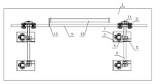
Fig. 1 is the structural representation of paint spray booth hydraulic lifting device of the present invention.
Fig. 2 is the plan structure scheme drawing of Fig. 1.
Among the figure: 1, paint spray booth, 2, column, 3, pinion stand, 4, lifter rack, 5, lifter wheel, 6, screw, 7, lifter plate, 8, pulley, 9, drive spindle, 10, adapter shaft, 11, guide holder, 12, connecting panel, 13, cylinder, 14, transmission gear.
The specific embodiment
Describe particular content of the present invention in detail below in conjunction with the drawings and specific embodiments.
As Fig. 1, shown in Figure 2, paint spray booth hydraulic lifting device, comprise: be arranged on four columns 2 in the paint spray booth 1, be respectively arranged with pinion stand 3 at four columns 2, in pinion stand 3, be provided with lifter rack 4, in pinion stand 3, be provided with the lifter wheel 5 that lifter rack 4 cooperatively interacts, lifter rack 4 is connected with lifter plate 7 by screw 6, in pinion stand 3, be provided with the pulley 8 that cooperatively interacts with lifter plate 7 one sides, be connected with two adapter shafts 10 by a drive spindle 9 between the described pinion stand 3, drive spindle 10 is arranged in the paint spray booth 1 by guide holder 11, the middle part of described drive spindle 9 is connected with cylinder 13 by connecting panel 12, the two ends of drive spindle 9 are connected with adapter shaft 10 by transmission gear 14 respectively, and described lifter wheel 5 is arranged on the described adapter shaft 10.
When above-mentioned paint spray booth hydraulic lifting device uses, workpiece is placed on the upper end of four lifter racks 4, the piston rod of cylinder 10 stretches out and promotes drive spindle 9, in drive spindle 9 moving process, driving adapter shaft 10 by transmission gear 14 rotates, adapter shaft 10 rotates and drives lifter wheel 5 rotations, and lifter wheel 5 cooperatively interacts with lifter rack 4, and the workpiece that drives on lifter rack 4 and the lifter plate 7 moves up.
Claims (1)
1. paint spray booth hydraulic lifting device, it is characterized in that: comprising: be arranged on four columns (2) in the paint spray booth (1), be respectively arranged with pinion stand (3) at four columns (2), in pinion stand (3), be provided with lifter rack (4), in pinion stand (3), be provided with the lifter wheel (5) that lifter rack (4) cooperatively interacts, lifter rack (4) is connected with lifter plate (7) by screw (6), in pinion stand (3), be provided with the pulley (8) that cooperatively interacts with lifter plate (7) one sides, be connected with two adapter shafts (10) by a drive spindle (9) between the described pinion stand (3), drive spindle (10) is arranged in the paint spray booth (1) by guide holder (11), the middle part of described drive spindle (9) is connected with cylinder (13) by connecting panel (12), the two ends of drive spindle (9) are connected with adapter shaft (10) by transmission gear (14) respectively, and described lifter wheel (5) is arranged on the described adapter shaft (10).
Priority Applications (1)
| Application Number | Priority Date | Filing Date | Title |
|---|---|---|---|
| CN 201310112645 CN103274332A (en) | 2013-04-02 | 2013-04-02 | Spray chamber hydraulic lifting device |
Applications Claiming Priority (1)
| Application Number | Priority Date | Filing Date | Title |
|---|---|---|---|
| CN 201310112645 CN103274332A (en) | 2013-04-02 | 2013-04-02 | Spray chamber hydraulic lifting device |
Publications (1)
| Publication Number | Publication Date |
|---|---|
| CN103274332A true CN103274332A (en) | 2013-09-04 |
Family
ID=49056995
Family Applications (1)
| Application Number | Title | Priority Date | Filing Date |
|---|---|---|---|
| CN 201310112645 Pending CN103274332A (en) | 2013-04-02 | 2013-04-02 | Spray chamber hydraulic lifting device |
Country Status (1)
| Country | Link |
|---|---|
| CN (1) | CN103274332A (en) |
Cited By (6)
| Publication number | Priority date | Publication date | Assignee | Title |
|---|---|---|---|---|
| CN103754736A (en) * | 2014-01-29 | 2014-04-30 | 中交天津航道局有限公司 | Double-drive lifting mechanism |
| CN103754738A (en) * | 2014-01-29 | 2014-04-30 | 河海大学常州校区 | Double-driving lifting mechanism |
| CN105174129A (en) * | 2015-10-19 | 2015-12-23 | 崔会斌 | Lifting device for oxygen acetylene cylinder detection |
| CN106583132A (en) * | 2016-11-30 | 2017-04-26 | 重庆市庆颖摩托车配件有限公司 | Vacuum paint spraying device for air cylinder |
| CN109704222A (en) * | 2019-01-15 | 2019-05-03 | 中铁工程装备集团盾构制造有限公司 | A kind of shield machine penstock installation lifting device and method |
| CN110026539A (en) * | 2019-05-20 | 2019-07-19 | 北京航大新材科技有限公司 | A kind of casting machine of the quick mode locking of energy |
-
2013
- 2013-04-02 CN CN 201310112645 patent/CN103274332A/en active Pending
Cited By (10)
| Publication number | Priority date | Publication date | Assignee | Title |
|---|---|---|---|---|
| CN103754736A (en) * | 2014-01-29 | 2014-04-30 | 中交天津航道局有限公司 | Double-drive lifting mechanism |
| CN103754738A (en) * | 2014-01-29 | 2014-04-30 | 河海大学常州校区 | Double-driving lifting mechanism |
| CN103754738B (en) * | 2014-01-29 | 2016-04-27 | 河海大学常州校区 | A kind of Dual Drive lifting mechanism |
| CN103754736B (en) * | 2014-01-29 | 2016-06-29 | 中交天津航道局有限公司 | Dual Drive elevating mechanism |
| CN105174129A (en) * | 2015-10-19 | 2015-12-23 | 崔会斌 | Lifting device for oxygen acetylene cylinder detection |
| CN106583132A (en) * | 2016-11-30 | 2017-04-26 | 重庆市庆颖摩托车配件有限公司 | Vacuum paint spraying device for air cylinder |
| CN109704222A (en) * | 2019-01-15 | 2019-05-03 | 中铁工程装备集团盾构制造有限公司 | A kind of shield machine penstock installation lifting device and method |
| CN109704222B (en) * | 2019-01-15 | 2024-02-09 | 中铁工程装备集团盾构制造有限公司 | Lifting device and method for shield tunneling machine steel pipe installation |
| CN110026539A (en) * | 2019-05-20 | 2019-07-19 | 北京航大新材科技有限公司 | A kind of casting machine of the quick mode locking of energy |
| CN110026539B (en) * | 2019-05-20 | 2023-10-31 | 北京航大新材科技有限公司 | Casting machine capable of rapidly locking mold |
Similar Documents
| Publication | Publication Date | Title |
|---|---|---|
| CN103274332A (en) | Spray chamber hydraulic lifting device | |
| CN204675736U (en) | A kind of pharmaceuticals industry is produced and is used rack-and-gear lift system | |
| CN104175312B (en) | A kind of mechanical hand producing precast concrete wall panel | |
| CN104259036A (en) | Spraying manipulator | |
| CN106926210A (en) | A kind of Multidirectional motion electric power apparatus examination platform | |
| CN102556894A (en) | Synchronous lifting platform with four columns | |
| CN104493466A (en) | Medical precision regulator assembling device and assembling method thereof | |
| CN204208716U (en) | Spray equipment is assisted in the bottom of spray coating mechanical hand | |
| CN104368996A (en) | Machining platform transversely-moving device | |
| CN203173744U (en) | Spray room hydraulic lifting device | |
| CN202824729U (en) | Drilling device | |
| CN105236082B (en) | One kind is by survey time turns elevating mechanism | |
| CN201960749U (en) | Novel screw press | |
| CN204076258U (en) | A kind of manipulator producing precast concrete wall panel | |
| CN202684589U (en) | Clamping device | |
| CN203620907U (en) | Lifting machine for powder spraying | |
| CN204208720U (en) | Spray coating mechanical hand | |
| CN204296091U (en) | The push plate device of trigger squeeze | |
| CN105289930B (en) | A kind of point gum machine | |
| CN204208715U (en) | The slide mechanism of spray coating mechanical hand | |
| CN204490418U (en) | Bay-lift Level Change device | |
| CN202895898U (en) | Z-axis lifting device for printing machine working platform | |
| CN202784867U (en) | Novel full-automatic setting machine | |
| CN203566111U (en) | Cylinder stroke-doubling mechanism | |
| CN203956910U (en) | Crystal pearl processing equipment hand |
Legal Events
| Date | Code | Title | Description |
|---|---|---|---|
| C06 | Publication | ||
| PB01 | Publication | ||
| C02 | Deemed withdrawal of patent application after publication (patent law 2001) | ||
| WD01 | Invention patent application deemed withdrawn after publication |
Application publication date: 20130904 |