CN103273438A - Optical fiber fixing clamp - Google Patents
Optical fiber fixing clamp Download PDFInfo
- Publication number
- CN103273438A CN103273438A CN2013101537423A CN201310153742A CN103273438A CN 103273438 A CN103273438 A CN 103273438A CN 2013101537423 A CN2013101537423 A CN 2013101537423A CN 201310153742 A CN201310153742 A CN 201310153742A CN 103273438 A CN103273438 A CN 103273438A
- Authority
- CN
- China
- Prior art keywords
- push rod
- eccentric wheel
- base
- hole
- optical fiber
- Prior art date
- Legal status (The legal status is an assumption and is not a legal conclusion. Google has not performed a legal analysis and makes no representation as to the accuracy of the status listed.)
- Granted
Links
Images


Landscapes
- Mechanical Coupling Of Light Guides (AREA)
- Light Guides In General And Applications Therefor (AREA)
Abstract
An optical fiber fixing clamp mainly comprises an eccentric wheel, a push rod, a pressing plate and a clamp base, wherein an eccentric wheel base is fixed on the clamp base, the eccentric wheel is arranged on the eccentric wheel base, and a handle is arranged on the outer edge of the eccentric wheel. A push rod base with a through hole is fixed on the clamp base, the push rod penetrates through the through hole to be arranged on the push rod base, a push rod cap is contacted with the outer edge of the eccentric wheel, the top end of a large hole of a push rod sleeve is provided with threads to be used for fixing the push rod cap, a marking post is placed into a small hole of the push rod sleeve, inner springs and outer springs are arranged inside and outside the push rod sleeve respectively, scales are formed in the marking post, a through hole is formed in the bottom end of the marking post and used for insertion of a pressing plate pin to be connected with the concave pressing plate. Two side faces, corresponding to the pressing plate, of a transverse plate of the clamp base are respectively provided with a width maintaining plate formed by two U type plates, and 2-4 through holes are formed in the transverse plate of the clamp base. The optical fiber fixing clamp is simple in structure, capable of achieving self-locking, adjustable in stress, and capable of flexibly positioning and clamping an optical fiber, cannot damage the sheath of the optical fiber, and is uniform in stress of the optical fiber and good in safety.
Description
Technical field
The present invention relates to a kind of anchor clamps, particularly a kind of fiber clamp.
Background technology
Optical fiber is being brought into play irreplaceable effect in optical sensing, fiber optic communication, the optical fiber stationary fixture seems particularly important as the device of fixed fiber in optical fiber preparation and test thereof.
In order to utilize optical fiber properties better, need carry out various scientific experiments to it, often need in the test optical fiber is fixed, and optic fibre force is had certain requirement, and traditional machine tool class anchor clamps are unsuitable for the tiny optical fiber of clamping, and bad assurance dynamics in clamping, the destruction of easily causing optical fiber, existing optical fiber stationary fixture versatility is poor, complex structure, the manufacturing cost height, flexibility is low, complex operation.
Summary of the invention
The object of the present invention is to provide a kind of simple in structure, be easy to install, easy to operate optical fiber stationary fixture.
Technical scheme of the present invention is as follows:
The present invention mainly comprises eccentric wheel, push rod, pressing plate and clamp base, wherein clamp base is the inverted T shape structure, the eccentric wheel base is fixed on the top of clamp base riser one side, eccentric wheel is installed on the above-mentioned eccentric wheel base by eccentric key, eccentric outer rim is provided with screw, and handle is threaded with eccentric wheel.Below eccentric wheel, the push rod base that has through hole is fixed on the bottom of above-mentioned clamp base riser the same side, push rod passes above-mentioned through hole and is arranged on the push rod base, push rod is by the push rod cap, inner spring, push rod housing and mark post are formed, the push rod cap contacts with above-mentioned eccentric wheel outer rim, the push rod cap is nut type, push rod housing is provided with small one and large one notch cuttype hole, the macropore top is provided with screw thread in order to fixing push rod cap, and the mark post of T font is put into aperture, and mark post and push rod housing are matched in clearance, be provided with inner spring between push rod housing inner push-rod cap and the mark post, be provided with scale at mark post, its bottom is provided with through hole, is used for inserting pressure plate stud and connects the matrix pressing plate.Be provided with outer spring outside push rod housing, this outer spring is respectively against the last plane of push rod cap and push rod base.Both sides at the clamp base transverse slat corresponding with above-mentioned pressing plate are provided with the width holding plate, and this width holding plate is two relative U-shaped plates, fixes by screw respectively.Be provided with 2-4 through hole at the clamp base transverse slat, in order to anchor clamps are connected and be fixed on the equipment such as lathe.
During use, at first upwards driving handle causes under the push rod spring action outside and upsprings, optical fiber is passed between width holding plate plate, regulate width holding plate distance between plates from, optical fiber is contacted with the width holding plate, tighten the screw on the width holding plate, rotate handle then, make the pressing plate pressed fiber, the big I of thrust is reflected by the mark post scale value.Eccentric wheel can keep good good self-locking state in the whole operation process.Upwards driving handle makes under the push rod spring action outside and upsprings, and unscrews the screw on the width holding plate, enlarge distance between plates from, take out optical fiber.
The present invention compared with prior art has following advantage:
(1) simple for structure, can self-locking, easy to operate.
(2) the stressed size of optical fiber can be controlled by the stroke of spring, and the appearance of optical fiber situation, reliability height can be effectively avoided damaging by pressure.
(3) with turnable pressing plate pressed fiber, regulate the location of width holding plate, be applicable to the various optical fiber of clamping, and can be flexibly, accurately optical fiber is positioned, clamps, and can not damage the optical fiber crust, optic fibre force is even, security is good.
Description of drawings
Fig. 1 is three-dimensional simplified schematic diagram of the present invention;
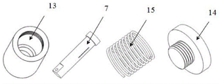
Fig. 2 is the simplified schematic diagram of push rod of the present invention;
Fig. 3 is the cut-away view of push rod of the present invention;
Fig. 4 is push rod part schematic diagram of the present invention.
Outer spring in the drawings, 1, handle, 2, eccentric wheel, 3, eccentric key, 4, push rod, 5,, 6, push rod base, 7, mark post, 8, pressing plate, 9, pressure plate stud, 10, the width holding plate, 11, clamp base, 12, the eccentric wheel base, 13, push rod housing, 14, the push rod cap, 15, inner spring.
The specific embodiment
In a kind of optical fiber stationary fixture schematic diagram shown in Figure 1, clamp base 11 is the inverted T shape structure, eccentric wheel base 12 is fixed on the top of clamp base riser one side, eccentric wheel 2 is installed on the above-mentioned eccentric wheel base by eccentric key 3, eccentric outer rim is provided with screw, and handle 1 is threaded with eccentric wheel.Below eccentric wheel, the push rod base 6 that has through hole is fixed on the bottom of above-mentioned clamp base riser the same side, and push rod 4 passes above-mentioned through hole and is arranged on the push rod base, and push rod cap 14 contacts with above-mentioned eccentric wheel outer rim.Shown in Fig. 2,3 and 4, the push rod cap is nut type, push rod housing 13 is provided with small one and large one notch cuttype hole, the macropore top is provided with screw thread in order to fixing push rod cap, and the mark post 7 of T font is put into aperture, and mark post and push rod housing are matched in clearance, be provided with inner spring 15 between push rod housing inner push-rod cap and the mark post, be provided with scale at mark post, its bottom is provided with through hole, is used for inserting pressure plate stud 9 and connects matrix pressing plate 8.Be provided with outer spring 5 outside push rod housing, this outer spring is respectively against the last plane of push rod cap and push rod base.Both sides at the clamp base transverse slat corresponding with above-mentioned pressing plate are provided with width holding plate 10, and this width holding plate is two relative U-shaped plates, fixes by screw respectively.Be provided with 4 through holes at the clamp base transverse slat, in order to anchor clamps are connected and be fixed on the equipment such as lathe.
Claims (1)
1. optical fiber stationary fixture, mainly comprise eccentric wheel, push rod, pressing plate, clamp base, it is characterized in that: its clamp base is the inverted T shape structure, the eccentric wheel base is fixed on the top of clamp base riser one side, eccentric wheel is installed on the above-mentioned eccentric wheel base by eccentric key, eccentric outer rim is provided with screw, and handle is threaded with eccentric wheel; Below eccentric wheel, the push rod base that has through hole is fixed on the bottom of above-mentioned clamp base riser the same side, push rod passes above-mentioned through hole and is arranged on the push rod base, push rod is by the push rod cap, inner spring, push rod housing and mark post are formed, the push rod cap contacts with above-mentioned eccentric wheel outer rim, the push rod cap is nut type, push rod housing is provided with small one and large one notch cuttype hole, the macropore top is provided with screw thread in order to fixing push rod cap, and the mark post of T font is put into aperture, and mark post and push rod housing are matched in clearance, be provided with inner spring between push rod housing inner push-rod cap and the mark post, be provided with scale at mark post, its bottom is provided with through hole, is used for inserting pressure plate stud and connects the matrix pressing plate; Be provided with outer spring outside push rod housing, this outer spring is respectively against the last plane of push rod cap and push rod base; Both sides at the clamp base transverse slat corresponding with above-mentioned pressing plate are provided with the width holding plate, and this width holding plate is two relative U-shaped plates, fixes by screw respectively; Being provided with 2-4 at the clamp base transverse slat connects anchor clamps and is fixed on through hole on the equipment such as lathe.
Priority Applications (1)
| Application Number | Priority Date | Filing Date | Title |
|---|---|---|---|
| CN201310153742.3A CN103273438B (en) | 2013-04-27 | 2013-04-27 | Optical fiber fixing clamp |
Applications Claiming Priority (1)
| Application Number | Priority Date | Filing Date | Title |
|---|---|---|---|
| CN201310153742.3A CN103273438B (en) | 2013-04-27 | 2013-04-27 | Optical fiber fixing clamp |
Publications (2)
| Publication Number | Publication Date |
|---|---|
| CN103273438A true CN103273438A (en) | 2013-09-04 |
| CN103273438B CN103273438B (en) | 2014-12-24 |
Family
ID=49056114
Family Applications (1)
| Application Number | Title | Priority Date | Filing Date |
|---|---|---|---|
| CN201310153742.3A Expired - Fee Related CN103273438B (en) | 2013-04-27 | 2013-04-27 | Optical fiber fixing clamp |
Country Status (1)
| Country | Link |
|---|---|
| CN (1) | CN103273438B (en) |
Cited By (8)
| Publication number | Priority date | Publication date | Assignee | Title |
|---|---|---|---|---|
| CN104698557A (en) * | 2015-04-03 | 2015-06-10 | 上海电缆研究所 | Manufacturing clamp for optical fiber array |
| CN105258860A (en) * | 2015-11-21 | 2016-01-20 | 重庆市山城燃气设备有限公司 | Gas meter sealing performance detection apparatus with duplex quick clamping device |
| CN105424283A (en) * | 2015-11-21 | 2016-03-23 | 重庆市山城燃气设备有限公司 | Double-linked rapid clamping apparatus for detection of sealing performance of gas meter |
| CN106002380A (en) * | 2016-06-30 | 2016-10-12 | 苏州健雄职业技术学院 | Clamping fixture for multiple thin parts |
| CN109397009A (en) * | 2018-12-20 | 2019-03-01 | 阚大荣 | A kind of polishing mold for convex surface for optical mirror slip |
| CN110653547A (en) * | 2019-09-16 | 2020-01-07 | 邹鑫 | A welded platform for auto-parts processing |
| CN110911115A (en) * | 2019-12-11 | 2020-03-24 | 杭州优朴信息技术有限公司 | Card inserting type heat radiating device on miniature transformer |
| CN112299704A (en) * | 2020-11-13 | 2021-02-02 | 中国电子科技集团公司第四十六研究所 | Clamp and clamping method for improving geometric precision of polarization maintaining optical fiber preform |
Citations (7)
| Publication number | Priority date | Publication date | Assignee | Title |
|---|---|---|---|---|
| EP0036369A1 (en) * | 1980-03-14 | 1981-09-23 | Lignes Telegraphiques Et Telephoniques L.T.T. | Method and apparatus for coupling fibre-optical cables on the working site |
| CN2303309Y (en) * | 1997-08-20 | 1999-01-06 | 中国科学院安徽光学精密机械研究所 | Simple type three-D optical fiber regulation frame |
| CN2852154Y (en) * | 2005-11-30 | 2006-12-27 | 捷芯科技股份有限公司 | Universal clamp for detecting optic fiber patch cord |
| DE202008013804U1 (en) * | 2008-11-28 | 2009-04-16 | Chang, Peter | Nanopositioner for aligning optical elements without electricity |
| CN202438942U (en) * | 2012-02-28 | 2012-09-19 | 南京烽火藤仓光通信有限公司 | Optical fiber fixing device |
| CN103009306A (en) * | 2012-12-14 | 2013-04-03 | 中国电子科技集团公司第十一研究所 | Optical fiber fixing device |
| CN103064164A (en) * | 2012-12-21 | 2013-04-24 | 燕山大学 | Multi-core belt-shaped optical fiber fixture with self-locking and anti-skidding function |
-
2013
- 2013-04-27 CN CN201310153742.3A patent/CN103273438B/en not_active Expired - Fee Related
Patent Citations (7)
| Publication number | Priority date | Publication date | Assignee | Title |
|---|---|---|---|---|
| EP0036369A1 (en) * | 1980-03-14 | 1981-09-23 | Lignes Telegraphiques Et Telephoniques L.T.T. | Method and apparatus for coupling fibre-optical cables on the working site |
| CN2303309Y (en) * | 1997-08-20 | 1999-01-06 | 中国科学院安徽光学精密机械研究所 | Simple type three-D optical fiber regulation frame |
| CN2852154Y (en) * | 2005-11-30 | 2006-12-27 | 捷芯科技股份有限公司 | Universal clamp for detecting optic fiber patch cord |
| DE202008013804U1 (en) * | 2008-11-28 | 2009-04-16 | Chang, Peter | Nanopositioner for aligning optical elements without electricity |
| CN202438942U (en) * | 2012-02-28 | 2012-09-19 | 南京烽火藤仓光通信有限公司 | Optical fiber fixing device |
| CN103009306A (en) * | 2012-12-14 | 2013-04-03 | 中国电子科技集团公司第十一研究所 | Optical fiber fixing device |
| CN103064164A (en) * | 2012-12-21 | 2013-04-24 | 燕山大学 | Multi-core belt-shaped optical fiber fixture with self-locking and anti-skidding function |
Cited By (9)
| Publication number | Priority date | Publication date | Assignee | Title |
|---|---|---|---|---|
| CN104698557A (en) * | 2015-04-03 | 2015-06-10 | 上海电缆研究所 | Manufacturing clamp for optical fiber array |
| CN105258860A (en) * | 2015-11-21 | 2016-01-20 | 重庆市山城燃气设备有限公司 | Gas meter sealing performance detection apparatus with duplex quick clamping device |
| CN105424283A (en) * | 2015-11-21 | 2016-03-23 | 重庆市山城燃气设备有限公司 | Double-linked rapid clamping apparatus for detection of sealing performance of gas meter |
| CN106002380A (en) * | 2016-06-30 | 2016-10-12 | 苏州健雄职业技术学院 | Clamping fixture for multiple thin parts |
| CN109397009A (en) * | 2018-12-20 | 2019-03-01 | 阚大荣 | A kind of polishing mold for convex surface for optical mirror slip |
| CN110653547A (en) * | 2019-09-16 | 2020-01-07 | 邹鑫 | A welded platform for auto-parts processing |
| CN110911115A (en) * | 2019-12-11 | 2020-03-24 | 杭州优朴信息技术有限公司 | Card inserting type heat radiating device on miniature transformer |
| CN112299704A (en) * | 2020-11-13 | 2021-02-02 | 中国电子科技集团公司第四十六研究所 | Clamp and clamping method for improving geometric precision of polarization maintaining optical fiber preform |
| CN112299704B (en) * | 2020-11-13 | 2023-12-29 | 中国电子科技集团公司第四十六研究所 | Clamp and clamping method for improving geometric accuracy of polarization maintaining optical fiber preform |
Also Published As
| Publication number | Publication date |
|---|---|
| CN103273438B (en) | 2014-12-24 |
Similar Documents
| Publication | Publication Date | Title |
|---|---|---|
| CN103273438B (en) | Optical fiber fixing clamp | |
| CN102928288B (en) | A kind of tensile test fixture | |
| CN202292517U (en) | Indexible elastic pressure plate | |
| CN105445101A (en) | Experiment clamp capable of being adjusted and aligned and used for determining tensile strength of rocks with splitting method and method for determining tensile strength of rocks | |
| CN204202989U (en) | A kind of small punch test fixture | |
| CN103207055A (en) | Spring fatigue strength testing device | |
| CN103472558B (en) | Optical lens device clamping device | |
| CN204731097U (en) | A kind of securing member fracture strength test fixture | |
| US10124392B2 (en) | Pipe flare processing device having a view hole | |
| CN103644797A (en) | Position accuracy detection testing fixture | |
| CN105458344A (en) | Connecting rod locating drill jig | |
| CN102494946A (en) | Tensile strength test apparatus for screw members | |
| CN108680082A (en) | A kind of forging measuring device | |
| CN106092737B (en) | A kind of device for power battery module side plate tension test | |
| CN203465462U (en) | Multifunctional optical lens device clamping tool | |
| CN203696003U (en) | Tuning clamp with axial positioning device | |
| CN208921023U (en) | A kind of forging measuring device | |
| CN103115815A (en) | Jig for testing notch sensitivity of bolt | |
| CN211136929U (en) | Tool convenient to assemble and disassemble | |
| CN104007023B (en) | For checking the device of fused fiber splice point reliability | |
| CN103182643A (en) | Subpackage assembly fixture for engine piston | |
| CN109163893A (en) | A kind of flange face fastener fatigue test frock | |
| CN214238000U (en) | Positioning pin pressing rod | |
| CN204640024U (en) | A kind of bolt fatigue test clamping device and centering tooling thereof | |
| CN106153444B (en) | A kind of device for power battery module side plate tension test |
Legal Events
| Date | Code | Title | Description |
|---|---|---|---|
| C06 | Publication | ||
| PB01 | Publication | ||
| C10 | Entry into substantive examination | ||
| SE01 | Entry into force of request for substantive examination | ||
| C14 | Grant of patent or utility model | ||
| GR01 | Patent grant | ||
| CF01 | Termination of patent right due to non-payment of annual fee | ||
| CF01 | Termination of patent right due to non-payment of annual fee |
Granted publication date: 20141224 Termination date: 20170427 |