CN103245535A - Exhaust gas sampling device - Google Patents
Exhaust gas sampling device Download PDFInfo
- Publication number
- CN103245535A CN103245535A CN201310051307XA CN201310051307A CN103245535A CN 103245535 A CN103245535 A CN 103245535A CN 201310051307X A CN201310051307X A CN 201310051307XA CN 201310051307 A CN201310051307 A CN 201310051307A CN 103245535 A CN103245535 A CN 103245535A
- Authority
- CN
- China
- Prior art keywords
- temperature
- exhaust
- exhaust gas
- heating
- urea
- Prior art date
- Legal status (The legal status is an assumption and is not a legal conclusion. Google has not performed a legal analysis and makes no representation as to the accuracy of the status listed.)
- Pending
Links
Images


Classifications
-
- G—PHYSICS
- G01—MEASURING; TESTING
- G01N—INVESTIGATING OR ANALYSING MATERIALS BY DETERMINING THEIR CHEMICAL OR PHYSICAL PROPERTIES
- G01N1/00—Sampling; Preparing specimens for investigation
- G01N1/02—Devices for withdrawing samples
- G01N1/22—Devices for withdrawing samples in the gaseous state
- G01N1/2247—Sampling from a flowing stream of gas
- G01N1/2258—Sampling from a flowing stream of gas in a stack or chimney
-
- F—MECHANICAL ENGINEERING; LIGHTING; HEATING; WEAPONS; BLASTING
- F01—MACHINES OR ENGINES IN GENERAL; ENGINE PLANTS IN GENERAL; STEAM ENGINES
- F01N—GAS-FLOW SILENCERS OR EXHAUST APPARATUS FOR MACHINES OR ENGINES IN GENERAL; GAS-FLOW SILENCERS OR EXHAUST APPARATUS FOR INTERNAL COMBUSTION ENGINES
- F01N3/00—Exhaust or silencing apparatus having means for purifying, rendering innocuous, or otherwise treating exhaust
- F01N3/08—Exhaust or silencing apparatus having means for purifying, rendering innocuous, or otherwise treating exhaust for rendering innocuous
- F01N3/10—Exhaust or silencing apparatus having means for purifying, rendering innocuous, or otherwise treating exhaust for rendering innocuous by thermal or catalytic conversion of noxious components of exhaust
- F01N3/18—Exhaust or silencing apparatus having means for purifying, rendering innocuous, or otherwise treating exhaust for rendering innocuous by thermal or catalytic conversion of noxious components of exhaust characterised by methods of operation; Control
- F01N3/20—Exhaust or silencing apparatus having means for purifying, rendering innocuous, or otherwise treating exhaust for rendering innocuous by thermal or catalytic conversion of noxious components of exhaust characterised by methods of operation; Control specially adapted for catalytic conversion ; Methods of operation or control of catalytic converters
- F01N3/2066—Selective catalytic reduction [SCR]
- F01N3/208—Control of selective catalytic reduction [SCR], e.g. dosing of reducing agent
-
- F—MECHANICAL ENGINEERING; LIGHTING; HEATING; WEAPONS; BLASTING
- F01—MACHINES OR ENGINES IN GENERAL; ENGINE PLANTS IN GENERAL; STEAM ENGINES
- F01N—GAS-FLOW SILENCERS OR EXHAUST APPARATUS FOR MACHINES OR ENGINES IN GENERAL; GAS-FLOW SILENCERS OR EXHAUST APPARATUS FOR INTERNAL COMBUSTION ENGINES
- F01N2610/00—Adding substances to exhaust gases
- F01N2610/02—Adding substances to exhaust gases the substance being ammonia or urea
-
- F—MECHANICAL ENGINEERING; LIGHTING; HEATING; WEAPONS; BLASTING
- F01—MACHINES OR ENGINES IN GENERAL; ENGINE PLANTS IN GENERAL; STEAM ENGINES
- F01N—GAS-FLOW SILENCERS OR EXHAUST APPARATUS FOR MACHINES OR ENGINES IN GENERAL; GAS-FLOW SILENCERS OR EXHAUST APPARATUS FOR INTERNAL COMBUSTION ENGINES
- F01N2900/00—Details of electrical control or of the monitoring of the exhaust gas treating apparatus
- F01N2900/04—Methods of control or diagnosing
- F01N2900/0416—Methods of control or diagnosing using the state of a sensor, e.g. of an exhaust gas sensor
-
- F—MECHANICAL ENGINEERING; LIGHTING; HEATING; WEAPONS; BLASTING
- F01—MACHINES OR ENGINES IN GENERAL; ENGINE PLANTS IN GENERAL; STEAM ENGINES
- F01N—GAS-FLOW SILENCERS OR EXHAUST APPARATUS FOR MACHINES OR ENGINES IN GENERAL; GAS-FLOW SILENCERS OR EXHAUST APPARATUS FOR INTERNAL COMBUSTION ENGINES
- F01N2900/00—Details of electrical control or of the monitoring of the exhaust gas treating apparatus
- F01N2900/06—Parameters used for exhaust control or diagnosing
- F01N2900/14—Parameters used for exhaust control or diagnosing said parameters being related to the exhaust gas
- F01N2900/1402—Exhaust gas composition
-
- G—PHYSICS
- G01—MEASURING; TESTING
- G01N—INVESTIGATING OR ANALYSING MATERIALS BY DETERMINING THEIR CHEMICAL OR PHYSICAL PROPERTIES
- G01N1/00—Sampling; Preparing specimens for investigation
- G01N1/02—Devices for withdrawing samples
- G01N1/22—Devices for withdrawing samples in the gaseous state
- G01N1/2247—Sampling from a flowing stream of gas
- G01N1/2258—Sampling from a flowing stream of gas in a stack or chimney
- G01N2001/2261—Sampling from a flowing stream of gas in a stack or chimney preventing condensation (heating lines)
-
- Y—GENERAL TAGGING OF NEW TECHNOLOGICAL DEVELOPMENTS; GENERAL TAGGING OF CROSS-SECTIONAL TECHNOLOGIES SPANNING OVER SEVERAL SECTIONS OF THE IPC; TECHNICAL SUBJECTS COVERED BY FORMER USPC CROSS-REFERENCE ART COLLECTIONS [XRACs] AND DIGESTS
- Y02—TECHNOLOGIES OR APPLICATIONS FOR MITIGATION OR ADAPTATION AGAINST CLIMATE CHANGE
- Y02T—CLIMATE CHANGE MITIGATION TECHNOLOGIES RELATED TO TRANSPORTATION
- Y02T10/00—Road transport of goods or passengers
- Y02T10/10—Internal combustion engine [ICE] based vehicles
- Y02T10/12—Improving ICE efficiencies
Abstract
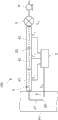
The present invention provides an exhaust gas sampling device intended to heat or cool a temperature of sampled exhaust gas flowing through a sampling line to a desired temperature in accordance with such as various exhaust gas conditions and usage conditions of the sampling line irrespective of a temperature of the exhaust gas flowing through an exhaust pipe, and includes: the sampling line (2) for sampling the exhaust gas to be introduced into an analyzing instrument (3); a plurality of heating parts (41) to (43) provided along the sampling line (2) from an upstream side to a downstream side for heating the exhaust gas flowing through the sampling line (2); and a temperature control part (5) for individually setting set temperatures (T1) to (T3) of the plurality of heating parts (41) to (43) using the temperature of the exhaust gas in the exhaust pipe (H) and a target temperature (TA) of the exhaust gas in an outlet side of the heating part (43) located in the most downstream as parameters.
Description
Technical field
The present invention relates to from the gas outlet of exhaust flow exhaust be taken a sample, the exhaust that then sampling is obtained imports the exhaust gas sampling device of analytical equipment.
Background technology
In the past, as being used for reducing the NO that contains from the engine exhaust of diesel motor discharge
XSystem, the urea SCR system is arranged.Described urea SCR system disposes the SCR catalyzer in gas outlet, inject urea ((NH in the upstream of this SCR catalyzer
2)
2CO).
Be injected into the interior urea of gas outlet because of (NH
2)
2CO+H
2O → 2NH
3+ CO
2Pyrolysis, generate NH
3Then, described NH
3In the SCR catalyzer with NO
XReaction, NO
XBe reduced into N
2, reduced NO thus
XSpecifically, in the SCR catalyzer, 4NH takes place
3+ 4NO+O
2→ 4N
2+ 6H
2O, 4NH
3+ 2NO
2+ O
2→ 3N
2+ 6H
2The reduction reaction of O.
In described system, if be injected into urea amount surplus in the gas outlet, then can cause discharging NH to the downstream of SCR catalyzer
3In addition, if the urea amount that is injected in the gas outlet is very few, the NO that contains in the exhaust then
XIn the SCR catalyzer, fully do not reduced, discharge to the downstream of SCR catalyzer and contain NO
XExhaust.Therefore, need make the urea amount that in the SCR catalyzer, injects become only amount.In addition, whether optimum for the urea amount that checks urea SCR, need detect the urea amount or the ammonia amount that contain in this exhaust to taking a sample by the exhaust behind the SCR catalyzer.
Exhaust measuring system in the past comprises: sampling pipe, from the downstream of SCR catalyzer exhaust is taken a sample; And NH
3Detector is measured the ammonia concentration in the exhaust that obtains by described sampling pipe sampling, according to passing through described NH
3The ammonia concentration that detector obtains judges whether the injection rate IR of urea is optimum.
, the delivery temperature that flows in gas outlet is because the duty difference of engine can become all temps (for example 100 ℃~500 ℃), and the urea that is injected into sometimes in the gas outlet does not have abundant thermal decomposition and hydrolysis just by the SCR catalyzer.Therefore there is following problems: though contain urea in the exhaust that sampling obtains, if thereby in sampling pipe, can not make the abundant thermal decomposition of urea and hydrolysis generate ammonia, can not judge then whether the urea injection rate IR is suitable amount.
At this, shown in patent documentation 1, be not adsorbed on the sampling pipe in order to make ammonia, or in order to make the not condensation of predetermined component in the exhaust, sometimes sampling pipe heating or the temperature that is cooled to stipulate.
; for in order to prevent from adsorbing or condensation etc. and sampling pipe being heated to for the scheme of uniform temperature; there is following problems: because of the serviceability temperature of the analytical equipment that is connected with sampling pipe or be located at filtrator in the sampling pipe and the restriction of the design temperature of throttle orifice etc. etc., can not be the sampling pipe heating or be cooled to make the temperature of regulation composition thermal decomposition such as the urea that contains in the exhaust and hydrolysis.For example, at the NH that is connected with sampling pipe
3The serviceability temperature of detector is under 113 ℃ the situation, if import NH want to make urea thermal decomposition in the exhaust of flowing or hydrolysis in sampling pipe after
3Detector, then under the delivery temperature that sampling obtains was 500 ℃ situation, in the stage that is cooled to 113 ℃ from 500 ℃, thermal decomposition etc. can take place in described urea.On the other hand, delivery temperature that sampling obtains than 113 ℃ of low situations under, the problem of existence is: only by this exhaust is heated to 113 ℃, can not make the predetermined component generation thermal decomposition of exhaust etc.
The prior art document
Patent documentation 1: Jap.P. open communique spy open 2010-236877 number
Summary of the invention
Fundamental purpose of the present invention is can be according to the service condition of various exhaust conditions and sampling pipe etc., the temperature heating of the exhaust that the sampling of flowing in sampling pipe is obtained or be cooled to temperature desired and irrelevant with the temperature of the exhaust of flowing in gas outlet.
That is, the invention provides a kind of exhaust gas sampling device, it comprises: sampling pipe, and the exhaust of flowing in gas outlet is taken a sample and the exhaust that sampling obtains is imported to analytical equipment; A plurality of heating parts, along on swim over to the downstream and be arranged on the described sampling pipe, the exhaust of flowing in described sampling pipe is heated; And temperature control part, the exhaust target temperature of outlet side of heating part that is positioned at downstream in the delivery temperature in the described gas outlet and the described a plurality of heating part as parameter, is set the design temperature of described a plurality of heating parts respectively.
According to described exhaust gas sampling device, because sampling pipe is provided with a plurality of heating parts, and with the delivery temperature in the gas outlet and the exhaust target temperature of outlet side of heating part that is positioned at downstream as parameter, respectively the design temperature of a plurality of heating parts is set, thus can with gas outlet in the exhaust that irrespectively sampling of flowing in sampling pipe obtained of delivery temperature the temperature heating or be cooled to temperature desired.For example by a plurality of heating parts, can form all temps gradient at sampling pipe along being from upstream to the downstream.In addition, even because various exhaust conditions make delivery temperature have wide scope, by the exhaust heating that sampling obtained with a plurality of heating parts or be cooled to temperature desired and control delivery temperature, delivery temperature is become be positioned at the exhaust target temperature of outlet side of the heating part in downstream, also can make delivery temperature meet service condition of sampling pipe etc.
In addition, at sampling pipe the structure that a heating part is heated or cooled off exhaust is set, by design temperature being set at the exhaust target temperature, can or be cooled to the exhaust target temperature the delivery temperature heating., after the temperature (first temperature) that delivery temperature is heated or be cooled to stipulate, can not or be cooled to described exhaust target temperature (second temperature) with the delivery temperature heating.In addition, also can consider to twine density etc. by control coil, form single thermograde with a heating part, exhaust heating or be cooled to target temperature, if but thermograde is single, then just determined often to be difficult to the temperature that in the heating part, can heat or be cooled to make delivery temperature become temperature desired according to the delivery temperature that flows into the heating part.
Under the delivery temperature situation lower than exhaust target temperature, only this delivery temperature is heated to the exhaust target temperature, the problem that exists the decomposition reaction of the predetermined component that contains in the exhaust fully not carry out.Therefore, preferably, when described delivery temperature was lower than described exhaust target temperature, described temperature control part was set the design temperature of the heating part that is positioned at upstream than the high temperature of described exhaust target temperature for.According to this scheme, because the design temperature of the heating part that is positioned at upstream is set for the temperature higher than exhaust target temperature, so can make delivery temperature temporarily become the temperature higher than exhaust target temperature, the decomposition reaction of the predetermined component that contains in the exhaust is fully carried out, imported to then in analytical equipment etc.
Specifically, use exhaust gas sampling device of the present invention, under the situation that the optimality that the urea of for example urea SCR system is injected checks etc., preferably, described exhaust contains urea and/or derives from the decomposition composition of urea, and the design temperature that is positioned at the heating part of upstream is the above temperature of hydrolysis temperature of the isocyanic acid (acid of イ ソ シ ア Application) that generates of the thermal decomposition because of described urea.According to this scheme, owing to isocyanic acid (HNCO) hydrolysis in sampling pipe that can make because of the thermal decomposition generation of urea, so can improve from ureagenetic ammonia (NH
3) measuring accuracy.Therefore, the optimality that for example can inject the urea of urea SCR system is carried out high-precision inspection.
In addition, according to the intensification condition of urea, because of the thermal decomposition generation cyanuric acid (acid of シ ア ヌ Le) of urea.Described cyanuric acid is resolved into isocyanic acid, as previously mentioned, in order to make the isocyanic acid hydrolysis, preferably, the described design temperature that is positioned at the heating part of upstream is that the cyanuric acid that the thermal decomposition because of described urea generates is resolved into temperature more than the decomposition temperature of isocyanic acid.
Preferably, described sampling pipe is provided with adiabatic expansion portion, described adiabatic expansion portion makes the exhaust adiabatic expansion that flows in described sampling pipe, described a plurality of heating part is arranged on the position by the upstream than described adiabatic expansion portion, described adiabatic expansion portion has: restriction makes the exhaust decompression that flows in described sampling pipe; And temperature regulation section, to carrying out adjustment by the exhaust after the described restriction, described temperature control part as parameter, is set the described exhaust target temperature of described delivery temperature and described restriction respectively to the design temperature of described a plurality of heating parts.By making exhaust decompression and thermal exhaust with restriction and temperature regulation section, can prevent predetermined component (for example hydrocarbon) condensation that contains in the exhaust by restriction.In addition, because with the temperature of exhaust target temperature as restriction, so under the situation that connects a plurality of analytical equipments etc. by restriction, become the temperature of the analytical equipment that for example serviceability temperature is the highest in a plurality of analytical equipments by the exhaust target temperature that makes restriction, can be used for a plurality of analytical equipments to exhaust gas sampling device of the present invention.In addition, this moment is owing to the heating of reducing pressure by restriction and temperature regulation section, so can be so that delivery temperature becomes the analytical equipment that the mode of the temperature lower than the exhaust target temperature of restriction imports exhaust regulation.
Specifically, under the situation of the measuring system that is used for hydrocarbon, exist described hydrocarbon condensation and ammonia to be adsorbed in the problem of described hydrocarbon.Therefore, preferably, the described exhaust target temperature of described restriction is the temperature higher than the condensing temperature of the hydrocarbon that contains in the described exhaust.In addition, owing to make the exhaust adiabatic expansion by adiabatic expansion portion, thus can prevent hydrocarbon condensation, and can make delivery temperature be reduced to NH
3The serviceability temperature of detector.
The present invention according to described formation, owing to can heat or be cooled to temperature desired with the delivery temperature that flows irrespectively obtains the sampling of flowing in sampling pipe delivery temperature in gas outlet, and can set the design temperature of a plurality of heating parts respectively, form all temps gradient, so the decomposition that can provide a kind of energy to be used for making the predetermined component that exhaust contains such as fully carries out at the exhaust gas sampling device of various uses.
Description of drawings
Fig. 1 has been to use the synoptic diagram of exhaust measuring system of the exhaust gas sampling device of present embodiment.
Fig. 2 is expression and the figure of Fig. 1 for an example of the design temperature of the exhaust gas sampling device of identical embodiment.
Fig. 3 is expression and the figure of Fig. 1 for an example of the design temperature of the exhaust gas sampling device of identical embodiment.
Fig. 4 is expression with Fig. 1 for the exhaust of identical embodiment with the synoptic diagram of the ammonia concentration when having or not the urea injection.
Fig. 5 is the synoptic diagram of the exhaust measuring system of distortion embodiment.
Description of reference numerals
100 ... the exhaust gas sampling device
H ... gas outlet
2 ... sampling pipe
21 ... sampling unit
22 ... the sampling pipe arrangement
23 ... adiabatic expansion portion
231 ... restriction (throttle orifice)
232 ... temperature regulation section (heating tube)
3 ... analytical equipment (NH
3Detector)
P ... pump
41 ... first heating part (being positioned at the heating part of upstream)
42 ... second heating part
43 ... the 3rd heating part (being positioned at the heating part in downstream)
T
GDelivery temperature
T
AThe exhaust target temperature
T
1The design temperature of first heating part
T
2The design temperature of second heating part
T
3The design temperature of the 3rd heating part
5 ... temperature control part
Embodiment
With reference to the accompanying drawings the exhaust measuring system of having used exhaust gas sampling device 100 of the present invention is described.
The exhaust measuring system of present embodiment is measured the predetermined component that contains from the exhaust that internal combustion engines such as for example diesel motor are discharged.
Specifically, as shown in Figure 1, exhaust gas sampling device 100 comprises: sampling pipe 2, be provided with sample tap SP in gas outlet H inside, and the exhaust that obtains by this sample tap SP sampling is imported analytical equipment 3; A plurality of heating part 41~43(are three in the present embodiment), be from upstream to the downstream and be arranged on the described sampling pipe 2, the exhaust of flowing in sampling pipe 2 is heated; Temperature control part 5 is with the delivery temperature T among the gas outlet H
GBe positioned at the exhaust target temperature T of outlet side of the heating part 43 in downstream in (near the delivery temperature of sampling spot (the sample tap SP)) and a plurality of heating part 41~43
AAs parameter, set a plurality of heating parts 41~43 design temperature separately respectively.
In addition, the analytical equipment 3 of present embodiment is to measure the NH of the ammonia concentration that contains in the exhaust by the absorption photometry of using laser
3Detector, analytical equipment 3 comprises: measuring cell; Laser irradiating part, from the light importing window importing laser of described measuring cell, the sample air in measuring cell is shone the good laser of rectilinearity; Optical detection part detects the transmission laser that comes out from measuring cell; And drawdown pump (being arranged on the pump P in sampling pipe 2 downstreams), be connected with measuring cell, to reducing pressure in the measuring cell.At this, be multipath reflection type measuring cell by making measuring cell, even be under the situation of low concentration at ammonia, also can increase detection sensitivity.In addition, laser irradiating part penetrates NH
3Absorption characteristic is arranged and have the laser of the oscillation wavelength of region of ultra-red wavelength such as mid infrared region, near infrared region or ultraviolet region, for example can consider to use semiconductor laser, Solid State Laser or liquid lasers etc. such as quanta cascade laser, variable-wavelength semiconductor laser.Optical detection part can consider to use for example MCT(HgCdTe of normal temperature action type) detecting device.Drawdown pump decompression in the measuring cell to the too small pressure that is difficult to measure of causing of for example 1kPa(gas concentration)~the 50kPa(peak not suddenly, becoming is easy to generate the pressure of interference with other gas componants), preferably decompression is difficult for causing NH to 20kPa~30kPa in this pressure limit
3Absorption, can realize measurable gas concentration and not produce interference with other gas componants.
Be provided with restriction (for example throttle orifice) 231 in sampling pipe arrangement 22, restriction 231 constitutes the part of adiabatic expansion portion 23, thus the decompression of exhaust adiabatic expansion and cooling that sampling is obtained.In addition, be equipped with filtrator 24 in the provided upstream near described restriction 231, filtrator 24 is used for the coal smoke of removal exhaust etc.Sampling pipe arrangement 22 is divided into upstream pipe arrangement 22A and downstream pipe arrangement 22B, and upstream pipe arrangement 22A is positioned at the upstream of restriction 231 and filtrator 24, and downstream pipe arrangement 22B is positioned at the downstream of restriction 231 and filtrator 24.Upstream pipe arrangement 22A is provided with a plurality of heating parts 41~43, and downstream pipe arrangement 22B is provided with for this downstream pipe arrangement 22B is remained on uniform temperature and (remains on as NH in the present embodiment
3Heating tube equitemperature adjusting portion 232 113 ℃ of the serviceability temperature of detector 3), that constitute the part of adiabatic expansion portion 23.In addition, because sampling pipe 2 is provided with restriction 231, so can prolong the hold-up time of exhaust in the pipe arrangement 22A of upstream.
A plurality of heating parts 41~43 are arranged on the upstream pipe arrangement 22A of the upstream that is positioned at restriction 231 and filtrator 24.Each heating part 41~43 is arranged on coiled type or the well heater cylindraceous on the face in the outside of upstream pipe arrangement 22A, and by the current value of the electric current on logical with temperature control part 5 controls described later, each heating part 41~43 is adjusted to the temperature of regulation.In addition, a plurality of heating parts 41~43 arrange along whole upstream pipe arrangement 22A, along the integral body in each zone in a plurality of zones that upstream pipe arrangement 22A all is divided into each heating part 41~43 are set.By heating part 41~43 is set like this, be easy to exhaust is heated or cooled off.
Specifically, as shown in Figure 2, at delivery temperature T
GThan exhaust target temperature T
AUnder the high situation, temperature control part 5 is as follows to design temperature T
1~T
3Set.
T
3=T
A+(T
G-T
A)/4
T
2=T
3+(T
G-T
A)/4
T
1=T
2+(T
G-T
A)/4
On the other hand, as shown in Figure 3, at delivery temperature T
GThan exhaust target temperature T
AUnder the low situation, the design temperature T of the heating part 41 that is positioned at upstream
1Set for than exhaust target temperature T
A(=190 ℃) high temperature.In more detail, the design temperature T of the heating part 41 that is positioned at upstream
1Be set at more than 300 ℃.Described 300 ℃ is the decomposition temperature that the cyanuric acid that the thermal decomposition because of urea produces is resolved into isocyanic acid, by the design temperature of the heating part 41 that is positioned at upstream is set at more than the described decomposition temperature, can make from ureagenetic ammonia amount many as far as possible, thereby can improve the measuring accuracy of ammonia concentration.
The design temperature T of second heating part 42
2Design temperature T with the 3rd heating part 43
3For example set as follows.
T
3=T
A+(T
1-T
A)/3
T
2=T
3+(T
1-T
A)/3
As described above, temperature control part 5 will be design temperature T
1With exhaust target temperature T
AThe temperature that obtains of difference five equilibrium as the design temperature T of second heating part 42, the 3rd heating part 43
2, T
3
At described (the delivery temperature T of situation arbitrarily
GThan exhaust target temperature T
AHigh situation and delivery temperature T
GThan exhaust target temperature T
ALow situation) under, to the design temperature T of a plurality of heating parts 41~43
1~T
3Set, make at delivery temperature T
GBe heated or cooled exhaust target temperature T
ATill, delivery temperature is changed at the hydrolysis temperature (160 ℃) of the isocyanic acid that the temperature that comprises the urea thermal decomposition (132 ℃), urea thermal decomposition generate with in the temperature range of whole temperature of the temperature (more than 300 ℃) of the cyanuric acid thermal decomposition of urea thermal decomposition generation.
In addition, at delivery temperature T
GThan exhaust target temperature T
AUnder the low situation, also can make the design temperature T of first heating part 41~the 3rd heating part 43
1~T
3With described exhaust target temperature T
AIdentical (190 ℃), thus make the temperature of the exhaust that obtains by the sampling behind the upstream pipe arrangement 22A of sampling pipe 2 become exhaust target temperature T
A
Then, with reference to the exhaust measuring system of Fig. 4 to the exhaust gas sampling device 100 by having used described structure, in the urea SCR mode, injected the situation of urea and do not inject under the situation of urea and pass through NH
3The variation of the ammonia concentration that detector 3 obtains describes.
Not injecting under the situation of urea, pass through NH
3The NH that detector 3 obtains
3Concentration is the original NH that contains at first the exhaust of discharging from internal combustion engine
3Concentration.Because even ammonia is heated in sampling pipe also and thermal decomposition can not take place, so there be not ammonia to be adsorbed under the situation of face etc. of sampling pipe inboard the NH in the exhaust of in gas outlet, flowing
3Concentration and pass through NH
3The NH that detector 3 obtains
3Concentration is identical.
On the other hand, under the situation of having injected urea, pass through NH
3The NH that detector 3 obtains
3Concentration is at described original NH
3Add on the concentration in the SCR catalyzer and NO
XThe NH that does not have the surplus of having reacted
3, and the exhaust that obtains because of sampling in the NH that generates of the urea thermal decomposition that contains and hydrolysis
3NH
3Concentration.Like this, owing to inject urea, produce ammonia and depart from (ア Application モ ニ ア ス リ ッ プ) (discharge ammonia).
As previously mentioned, because NH
3Concentration is injected the urea difference because having or not, so according to these two kinds of NH that measure
3Concentration poor can calculate the NH that produces because of urea SCR
3Concentration, can estimate the urea SCR system rightly.
According to the exhaust measuring system of the present embodiment of described formation, because sampling pipe 2 is provided with a plurality of heating parts 41~43, and with the delivery temperature T among the gas outlet H
GExhaust target temperature T with the outlet side of the heating part 43 that is positioned at downstream
AAs parameter, respectively the design temperature of a plurality of heating parts 41~43 is set, so can with gas outlet H in the exhaust that irrespectively sampling of flowing in sampling pipe 2 obtained of delivery temperature the temperature heating or be cooled to temperature desired.For example, in sampling pipe, by a plurality of heating parts 41~43, along on swim over to the downstream, can form the thermograde that for example is from upstream to the downstream and descends, all temps gradients such as thermograde that are from upstream to downstream increased temperature gradient, arc.In addition, even make delivery temperature T because of various exhaust conditions
GHave under the situation of wide region, by with a plurality of heating parts 41~43 exhaust being heated or being cooled to temperature desired, control delivery temperature T
G, make it become exhaust target temperature T
A, can make delivery temperature T
GThe service condition that meets filtrator 24, adiabatic expansion portion 23 or the analytical equipment 3 etc. that are arranged on the sampling pipe 2.
Particularly at delivery temperature T
GThan exhaust target temperature T
AUnder the low situation, because the design temperature T of the heating part 41 that is positioned at upstream
1Set for than exhaust target temperature T
A(=190 ℃) high more than 300 ℃, so not only can make isocyanic acid (HNCO) hydrolysis in sampling pipe 2 because of the thermal decomposition generation of urea, can also make the cyanuric acid thermal decomposition that generates because of the thermal decomposition of urea become isocyanic acid, owing to make the hydrolysis in sampling pipe 2 of this isocyanic acid, so can more correctly measure the ammonia concentration that derives from urea.
In addition because by swimming over to the runner decompression of measuring cell in the measuring cell of pump P and from restriction 231 following, so can increase with runner that measuring cell links to each other in the zone that is depressurized, can reduce NH
3Or the absorption of absorbing gas composition such as HC.Thus, even have NH
3Or the gas componant of the adsorbability of HC etc. is low concentration, also can carry out high-precision measurement, can improve the response speed to its measurement of concetration in addition.In addition, by the post-decompression sample air of temperature regulation section 232 heating, can prevent from following the dewfall in the pipe arrangement and the solution loss of the absorbing gas composition that produces, further improve measuring accuracy and response speed.In addition, when the absorption spectrum under the observation normal pressure, known the absorption peak width, but become decompression state in the measuring cell by making, can obtain more sharp-pointed peak, thereby can reduce NH
3The influence interfered of absorption peak.
In addition, the invention is not restricted to described embodiment.
For example, in said embodiment, at a plurality of measuring object composition (HC, NH
3Deng) the common use, exhaust gas sampling device 100 has adiabatic expansion portion 23, but also can not have adiabatic expansion portion 23, as shown in Figure 5, can directly import analytical equipment 3 to the exhaust that sampling obtains.In this case, under the situation of the ammonia in measuring exhaust, embodiment is such as described, because analytical equipment is NH
3Detector is so the exhaust target temperature for example is 113 ℃.
In addition, the exhaust measuring system of described embodiment has NH
3Detector, but in addition, also can have a plurality of analysers of measuring the various compositions that contain in the exhaust.In this case, can be arranged in series in a plurality of analysers on the sampling pipe 2, also can make the downstream pipe arrangement of sampling pipe 2 be divided into a plurality of branches runner, each analyser of configuration in each branch's runner.
In addition, the invention is not restricted to described embodiment, in the scope that does not break away from invention thought of the present invention, can carry out various distortion certainly.
Claims (6)
1. exhaust gas sampling device is characterized in that comprising:
Sampling pipe is taken a sample and the exhaust that sampling obtains is imported to analytical equipment the exhaust of flowing in gas outlet;
A plurality of heating parts, along on swim over to the downstream and be arranged on the described sampling pipe, the exhaust of flowing in described sampling pipe is heated; And
Temperature control part as parameter, is set the exhaust target temperature of outlet side of heating part that is positioned at downstream in the delivery temperature in the described gas outlet and the described a plurality of heating part respectively to the design temperature of described a plurality of heating parts.
2. exhaust gas sampling device according to claim 1, it is characterized in that, when described delivery temperature was lower than described exhaust target temperature, described temperature control part was set the design temperature of the heating part that is positioned at upstream than the high temperature of described exhaust target temperature for.
3. exhaust gas sampling device according to claim 1 is characterized in that,
Described exhaust contains urea and/or derives from the decomposition composition of urea,
The design temperature that is positioned at the heating part of upstream is the temperature more than the hydrolysis temperature of the isocyanic acid that generates of the thermal decomposition because of described urea.
4. exhaust gas sampling device according to claim 3 is characterized in that, the described design temperature that is positioned at the heating part of upstream is that the cyanuric acid that the thermal decomposition because of described urea generates is resolved into temperature more than the decomposition temperature of isocyanic acid.
5. exhaust gas sampling device according to claim 1 is characterized in that,
Described sampling pipe is provided with adiabatic expansion portion, and described adiabatic expansion portion makes the exhaust adiabatic expansion that flows in described sampling pipe,
Described a plurality of heating part is arranged on the position by the upstream than described adiabatic expansion portion,
Described adiabatic expansion portion has: restriction makes the exhaust decompression that flows in described sampling pipe; And temperature regulation section, to carrying out adjustment by the exhaust after the described restriction,
Described temperature control part as parameter, is set the described exhaust target temperature in described delivery temperature and the described restriction respectively to the design temperature of described a plurality of heating parts.
6. exhaust gas sampling device according to claim 5 is characterized in that, the described exhaust target temperature in the described restriction is the temperature higher than the condensing temperature of the hydrocarbon that contains in the described exhaust.
Applications Claiming Priority (2)
| Application Number | Priority Date | Filing Date | Title |
|---|---|---|---|
| JP2012-029921 | 2012-02-14 | ||
| JP2012029921A JP5752067B2 (en) | 2012-02-14 | 2012-02-14 | Exhaust gas sampling device |
Publications (1)
| Publication Number | Publication Date |
|---|---|
| CN103245535A true CN103245535A (en) | 2013-08-14 |
Family
ID=47738986
Family Applications (1)
| Application Number | Title | Priority Date | Filing Date |
|---|---|---|---|
| CN201310051307XA Pending CN103245535A (en) | 2012-02-14 | 2013-02-16 | Exhaust gas sampling device |
Country Status (5)
| Country | Link |
|---|---|
| US (1) | US9335235B2 (en) |
| EP (1) | EP2629077A3 (en) |
| JP (1) | JP5752067B2 (en) |
| CN (1) | CN103245535A (en) |
| IN (1) | IN2013CH00582A (en) |
Cited By (7)
| Publication number | Priority date | Publication date | Assignee | Title |
|---|---|---|---|---|
| CN104374610A (en) * | 2014-11-14 | 2015-02-25 | 华能国际电力股份有限公司 | Gas phase separation sampling system of urea hydrolysis reactor and sampling method gas phase separation sampling system of a urea hydrolysis reactor |
| CN107421790A (en) * | 2017-09-12 | 2017-12-01 | 南京友智科技有限公司 | A kind of more dot matrix mixing sampling apparatuses of gaseous contaminant and its method for sampling and blowback maintaining method |
| CN107631916A (en) * | 2017-09-12 | 2018-01-26 | 南京友智科技有限公司 | A kind of more dot matrix high-temperature sampling probes of gaseous contaminant |
| CN108956151A (en) * | 2018-09-30 | 2018-12-07 | 广西玉柴机器股份有限公司 | A kind of engine crankcase discharge sampler |
| CN109000996A (en) * | 2018-09-11 | 2018-12-14 | 云南森雅环保科技有限公司 | A kind of smoke dust sampling device |
| CN112763276A (en) * | 2020-10-22 | 2021-05-07 | 清华大学 | Particulate matter sampling device |
| CN112763275A (en) * | 2020-10-22 | 2021-05-07 | 清华大学 | Carbon film containing device for sampling particulate matters |
Families Citing this family (5)
| Publication number | Priority date | Publication date | Assignee | Title |
|---|---|---|---|---|
| CN104458349A (en) * | 2014-12-01 | 2015-03-25 | 安徽天德仪器科技有限公司 | Explosion-proof integrated electrical heating gas sampling device |
| KR101661064B1 (en) * | 2015-04-20 | 2016-09-30 | 한국기술교육대학교 산학협력단 | Thermal denuder, black carbon particle measurement system with the same and measurement method thereof |
| US9500580B1 (en) | 2015-06-04 | 2016-11-22 | General Electric Company | Gas detector and method of detection |
| CN109163944A (en) * | 2018-09-26 | 2019-01-08 | 苏州曼德克光电有限公司 | A kind of sampler of Multi-stage heating |
| CN116818440B (en) * | 2023-08-28 | 2023-11-10 | 四川国齐检测技术有限公司 | Indoor multi-point dynamic environment quality detection system and method |
Family Cites Families (24)
| Publication number | Priority date | Publication date | Assignee | Title |
|---|---|---|---|---|
| US3817100A (en) * | 1972-11-03 | 1974-06-18 | Ford Motor Co | Critical flow venturi |
| US3793887A (en) * | 1972-12-05 | 1974-02-26 | Ford Motor Co | Isokinetic sampling probe |
| JPS63267422A (en) * | 1987-04-23 | 1988-11-04 | Shikoku Chem Corp | Removing method for nitrogen oxide |
| JPS641931A (en) * | 1987-06-24 | 1989-01-06 | Toyota Motor Corp | White fume measuring apparatus |
| JPS63181848U (en) * | 1987-11-09 | 1988-11-24 | ||
| JPH01180635A (en) | 1988-01-13 | 1989-07-18 | Shikoku Nippon Denki Software Kk | Processor constituting system |
| JPH01180635U (en) * | 1988-05-31 | 1989-12-26 | ||
| US5196170A (en) * | 1990-11-13 | 1993-03-23 | Rupprecht & Patashnick Company, Inc. | Carbon particulate monitor |
| JP3201506B2 (en) * | 1995-02-21 | 2001-08-20 | 株式会社堀場製作所 | Gas sampling equipment |
| JP4399094B2 (en) * | 2000-08-09 | 2010-01-13 | 株式会社堀場製作所 | Exhaust gas sampling device |
| JP2003014625A (en) * | 2001-06-28 | 2003-01-15 | Ishikawajima Harima Heavy Ind Co Ltd | Simultaneous and continuous gas analyzer for so3 and nh3 |
| JP2003121319A (en) * | 2001-10-09 | 2003-04-23 | Mitsubishi Heavy Ind Ltd | Exhaust gas pretreatment apparatus and combustion control method |
| DE10353860B4 (en) * | 2003-11-18 | 2023-03-30 | Robert Bosch Gmbh | Sensor for detecting particles in a gas stream and method for its manufacture |
| JP2005308710A (en) * | 2004-03-26 | 2005-11-04 | Technica:Kk | Sampling conduit for vehicle exhaust gas measuring apparatus |
| US7418816B2 (en) * | 2005-09-01 | 2008-09-02 | Ford Global Technologies, Llc | Exhaust gas aftertreatment systems |
| US7334401B2 (en) * | 2006-01-19 | 2008-02-26 | Gm Global Technology Operations, Inc. | Apparatus for sensing particulates in a gas flow stream |
| US7644609B2 (en) * | 2008-06-04 | 2010-01-12 | Honeywell International Inc. | Exhaust sensor apparatus and method |
| DE102008049098A1 (en) * | 2008-09-26 | 2009-06-25 | Daimler Ag | Exhaust-gas cleaning system operating method for e.g. diesel engine of motor vehicle, involves determining aging condition of exhaust gas cleaning component by correlation of hydrocarbon existed in exhaust gas upstream of component |
| JP5232613B2 (en) * | 2008-12-08 | 2013-07-10 | 三菱重工業株式会社 | Exhaust gas purification device |
| JP2010185837A (en) * | 2009-02-13 | 2010-08-26 | Toyota Motor Corp | Exhaust gas measurement apparatus |
| JP5099056B2 (en) * | 2009-03-23 | 2012-12-12 | 株式会社豊田中央研究所 | Exhaust gas component measuring method and exhaust gas component measuring device |
| JP2010236877A (en) * | 2009-03-30 | 2010-10-21 | Chubu Electric Power Co Inc | Device and method for measurement of ammonia concentration in exhaust gas |
| JP5466870B2 (en) * | 2009-04-15 | 2014-04-09 | バブコック日立株式会社 | Method and apparatus for measuring mercury concentration |
| JP5667912B2 (en) * | 2010-05-18 | 2015-02-12 | 株式会社堀場製作所 | Adsorbable gas analyzer |
-
2012
- 2012-02-14 JP JP2012029921A patent/JP5752067B2/en not_active Expired - Fee Related
-
2013
- 2013-02-12 IN IN582CH2013 patent/IN2013CH00582A/en unknown
- 2013-02-13 EP EP13000741.2A patent/EP2629077A3/en not_active Withdrawn
- 2013-02-14 US US13/767,443 patent/US9335235B2/en active Active
- 2013-02-16 CN CN201310051307XA patent/CN103245535A/en active Pending
Cited By (8)
| Publication number | Priority date | Publication date | Assignee | Title |
|---|---|---|---|---|
| CN104374610A (en) * | 2014-11-14 | 2015-02-25 | 华能国际电力股份有限公司 | Gas phase separation sampling system of urea hydrolysis reactor and sampling method gas phase separation sampling system of a urea hydrolysis reactor |
| CN107421790A (en) * | 2017-09-12 | 2017-12-01 | 南京友智科技有限公司 | A kind of more dot matrix mixing sampling apparatuses of gaseous contaminant and its method for sampling and blowback maintaining method |
| CN107631916A (en) * | 2017-09-12 | 2018-01-26 | 南京友智科技有限公司 | A kind of more dot matrix high-temperature sampling probes of gaseous contaminant |
| CN107421790B (en) * | 2017-09-12 | 2023-11-03 | 南京友智科技有限公司 | Gaseous pollutant multi-point matrix mixed sampling device, sampling method thereof and blowback maintenance method |
| CN109000996A (en) * | 2018-09-11 | 2018-12-14 | 云南森雅环保科技有限公司 | A kind of smoke dust sampling device |
| CN108956151A (en) * | 2018-09-30 | 2018-12-07 | 广西玉柴机器股份有限公司 | A kind of engine crankcase discharge sampler |
| CN112763276A (en) * | 2020-10-22 | 2021-05-07 | 清华大学 | Particulate matter sampling device |
| CN112763275A (en) * | 2020-10-22 | 2021-05-07 | 清华大学 | Carbon film containing device for sampling particulate matters |
Also Published As
| Publication number | Publication date |
|---|---|
| JP5752067B2 (en) | 2015-07-22 |
| US20130209330A1 (en) | 2013-08-15 |
| US9335235B2 (en) | 2016-05-10 |
| JP2013167492A (en) | 2013-08-29 |
| IN2013CH00582A (en) | 2015-08-14 |
| EP2629077A3 (en) | 2017-12-27 |
| EP2629077A2 (en) | 2013-08-21 |
Similar Documents
| Publication | Publication Date | Title |
|---|---|---|
| CN103245535A (en) | Exhaust gas sampling device | |
| EP2343530B1 (en) | Apparatus for the monitoring and/or controlling of selective catalytic reduction processes | |
| ES2539307T3 (en) | Exhaust gas purification device | |
| CN102338740B (en) | Adsorptive gas analyzer | |
| CN101637703B (en) | Nitrogen oxide estimation downstream of a selective catalytic reduction catalyst | |
| CA2872782C (en) | Extractive continuous ammonia monitoring system | |
| CN109983207B (en) | Temperature estimation for a sensor | |
| CN103109172A (en) | Ammonia compound concentration measuring device and ammonia compound concentration measuring method | |
| CN105050693A (en) | Nox measuring system and method | |
| CN103344590B (en) | Flue gas denitrification monitoring system and method | |
| US20140010745A1 (en) | Method for operating an exhaust gas system for an internal combustion engine | |
| Michelin et al. | Advanced compact SCR mixer: BlueBox | |
| CN110671179B (en) | Internal combustion engine and method for measuring exhaust gas composition in exhaust gas | |
| Lu et al. | Study on urea deposits risk of after-treatment system based on deposits boundary method | |
| JP5985492B2 (en) | Gas analyzer | |
| JP2012167635A (en) | Exhaust gas recirculation apparatus and internal combustion engine system | |
| Rein et al. | 100 kHz Mid-IR TDLAS of Detonation Events with Fiber-Coupled Time-Division-Multiplexed Quantum Cascade Lasers | |
| CN106596467A (en) | Smoke denitration monitoring system and method | |
| RU2011118499A (en) | METHOD FOR OPERATING AN EVAPORATOR FOR PRODUCING GAS AMMONIA | |
| Liao et al. | Experimental investigation of heat transfer characteristics of UWS spray impingement in diesel SCR | |
| Žahour et al. | Self-sufficient system for NOx reduction | |
| Nagar et al. | Comparison of SCR Catalyst Performance on RMC SET Emission Cycle between an Engine and a High Flow Burner Rig | |
| Zahour et al. | Engine type independent SCR system | |
| US20170234182A1 (en) | High-end processing device for purification of exhaust of diesel engine | |
| RU2002121257A (en) | METHOD FOR DETERMINING OCTAN NUMBER OF FUEL AND DEVICE FOR ITS IMPLEMENTATION |
Legal Events
| Date | Code | Title | Description |
|---|---|---|---|
| C06 | Publication | ||
| PB01 | Publication | ||
| C02 | Deemed withdrawal of patent application after publication (patent law 2001) | ||
| WD01 | Invention patent application deemed withdrawn after publication |
Application publication date: 20130814 |