CN103237511A - Treatment tool for medical use, and manipulator - Google Patents
Treatment tool for medical use, and manipulator Download PDFInfo
- Publication number
- CN103237511A CN103237511A CN2011800566127A CN201180056612A CN103237511A CN 103237511 A CN103237511 A CN 103237511A CN 2011800566127 A CN2011800566127 A CN 2011800566127A CN 201180056612 A CN201180056612 A CN 201180056612A CN 103237511 A CN103237511 A CN 103237511A
- Authority
- CN
- China
- Prior art keywords
- functional unit
- arm
- pliers
- turning cylinder
- disposal
- Prior art date
- Legal status (The legal status is an assumption and is not a legal conclusion. Google has not performed a legal analysis and makes no representation as to the accuracy of the status listed.)
- Pending
Links
Images


Classifications
-
- A—HUMAN NECESSITIES
- A61—MEDICAL OR VETERINARY SCIENCE; HYGIENE
- A61B—DIAGNOSIS; SURGERY; IDENTIFICATION
- A61B17/00—Surgical instruments, devices or methods, e.g. tourniquets
- A61B17/28—Surgical forceps
- A61B17/29—Forceps for use in minimally invasive surgery
-
- A—HUMAN NECESSITIES
- A61—MEDICAL OR VETERINARY SCIENCE; HYGIENE
- A61B—DIAGNOSIS; SURGERY; IDENTIFICATION
- A61B34/00—Computer-aided surgery; Manipulators or robots specially adapted for use in surgery
- A61B34/30—Surgical robots
-
- A—HUMAN NECESSITIES
- A61—MEDICAL OR VETERINARY SCIENCE; HYGIENE
- A61B—DIAGNOSIS; SURGERY; IDENTIFICATION
- A61B34/00—Computer-aided surgery; Manipulators or robots specially adapted for use in surgery
- A61B34/30—Surgical robots
- A61B34/37—Master-slave robots
-
- A—HUMAN NECESSITIES
- A61—MEDICAL OR VETERINARY SCIENCE; HYGIENE
- A61B—DIAGNOSIS; SURGERY; IDENTIFICATION
- A61B34/00—Computer-aided surgery; Manipulators or robots specially adapted for use in surgery
- A61B34/70—Manipulators specially adapted for use in surgery
- A61B34/71—Manipulators operated by drive cable mechanisms
-
- A—HUMAN NECESSITIES
- A61—MEDICAL OR VETERINARY SCIENCE; HYGIENE
- A61B—DIAGNOSIS; SURGERY; IDENTIFICATION
- A61B17/00—Surgical instruments, devices or methods, e.g. tourniquets
- A61B17/00234—Surgical instruments, devices or methods, e.g. tourniquets for minimally invasive surgery
- A61B2017/00292—Surgical instruments, devices or methods, e.g. tourniquets for minimally invasive surgery mounted on or guided by flexible, e.g. catheter-like, means
- A61B2017/003—Steerable
-
- A—HUMAN NECESSITIES
- A61—MEDICAL OR VETERINARY SCIENCE; HYGIENE
- A61B—DIAGNOSIS; SURGERY; IDENTIFICATION
- A61B17/00—Surgical instruments, devices or methods, e.g. tourniquets
- A61B17/28—Surgical forceps
- A61B17/29—Forceps for use in minimally invasive surgery
- A61B2017/2901—Details of shaft
- A61B2017/2902—Details of shaft characterized by features of the actuating rod
-
- A—HUMAN NECESSITIES
- A61—MEDICAL OR VETERINARY SCIENCE; HYGIENE
- A61B—DIAGNOSIS; SURGERY; IDENTIFICATION
- A61B17/00—Surgical instruments, devices or methods, e.g. tourniquets
- A61B17/28—Surgical forceps
- A61B17/29—Forceps for use in minimally invasive surgery
- A61B2017/2926—Details of heads or jaws
- A61B2017/2932—Transmission of forces to jaw members
- A61B2017/2939—Details of linkages or pivot points
- A61B2017/294—Connection of actuating rod to jaw, e.g. releasable
-
- A—HUMAN NECESSITIES
- A61—MEDICAL OR VETERINARY SCIENCE; HYGIENE
- A61B—DIAGNOSIS; SURGERY; IDENTIFICATION
- A61B90/00—Instruments, implements or accessories specially adapted for surgery or diagnosis and not covered by any of the groups A61B1/00 - A61B50/00, e.g. for luxation treatment or for protecting wound edges
- A61B90/08—Accessories or related features not otherwise provided for
- A61B2090/0801—Prevention of accidental cutting or pricking
- A61B2090/08021—Prevention of accidental cutting or pricking of the patient or his organs
Abstract
This treatment tool (1) for medical use comprises a treatment part (10), an operation member (20) the leading end of which is connected to the base end section of the treatment part (10) and at least one portion of which is flexible, and a flexible sheath (30) into which the operation member (20) penetrates so as to be retractable in the longitudinal direction. The operation part (20) is formed so that a range thereof of a prescribed length from the end is a hard section (20A) having a higher rigidity than other sections. A connection section (17) between the treatment part (10) and the operation member (20) is located outside the sheath (30) when the operation member (20) is in its most retracted state. The length of the hard section (20A) is such that when the operation part (20) is in its most advanced state other regions of the operation part are not exposed outside of the sheath (30).
Description
Technical field
The mechanical hand that the present invention relates to the medical intervention instrument and have this medical intervention instrument.The application advocate based on November 30th, 2010 spy in Japanese publication be willing to 2010-267775 number priority, quote its content at this.
Background technology
In the past, in medical field, used the medical intervention instrument that biological tissue and surgical instrument etc. undergo surgery of controlling.These medical intervention instruments for example are installed on the mechanical hand of the medical manipulator system that constitutes master slave system, perhaps run through be inserted into endoscope pliers with in the passage, be imported in patient's etc. the body cavity, be used in the various operations.
In patent documentation 1, a kind of as the medical intervention instrument records the pliers of controlling with switching pliers portion freely.Line is connected with pliers portion via linkage, line is run through being inserted in the spiral sheath.When push-pull wire it being advanced and retreat in the longitudinal direction, pliers portion opens and closes.
The prior art document
Patent documentation
Patent documentation 1: the real fair 6-1696 communique of Japan
Summary of the invention
The problem that invention will solve
Controlling in the pliers of patent documentation 1 record, line is retreated under the maximum state, the connecting portion of linkage and line is positioned at sheath.The radial dimension of this connecting portion radial dimension more independent than line is big, therefore in such structure, needs to select the spiral sheath that can take in connecting portion, is difficult to make the treatment tool pathization.
The object of the present invention is to provide a kind of medical intervention instrument of easy pathization.
In addition, another object of the present invention is to provide a kind of mechanical hand of the part pathization that will in body cavity, undergo surgery easily.
For the means of dealing with problems
The medical intervention instrument of first mode of the present invention has: disposal portion, and it has a pair of pliers sheet that connects in the mode that can relatively rotate with respect to each other by the pliers turning cylinder; Functional unit, its at least a portion has flexible, and the terminal part of itself is connected with the base end part of described disposal portion; And sheath section, it has flexible, and described functional unit runs through in the mode that can advance and retreat in the longitudinal direction and is inserted in this sheath section, described functional unit is set as the hard portion that has higher rigidity than other positions from the scope of end predetermined length, the connecting portion of described disposal portion and described functional unit is set to, described functional unit is positioned under the maximum state beyond the described sheath section retreating into, the length of described hard portion is set to, and advances under the maximum state described other positions at described functional unit and is not exposed to beyond the described sheath section.
Preferably, described hard portion forms by implementing coating on the surface of described functional unit.
Preferably, the mechanical hand of second mode of the present invention, the medical intervention instrument with first mode of the present invention.
Preferably, described mechanical hand also has disposal portion rotating mechanism, this disposal portion rotating mechanism makes described disposal portion rotate centered by disposal portion turning cylinder, the border at described hard portion and described other positions constitutes: retreat under the maximum state for being set as linearity and described functional unit in described sheath section, than described disposal portion turning cylinder more near described disposal portion.
The effect of invention
According to medical intervention instrument of the present invention, can easily carry out pathization.
In addition, according to mechanical hand of the present invention, can be easily with the part pathization that undergos surgery in the body cavity, thus suitably undergo surgery.
Description of drawings
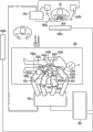
Fig. 1 is the figure of an example that the structure of the medical manipulator system of using medical intervention instrument of the present invention is shown.
Fig. 2 is the figure that the end side of this medical intervention instrument is shown.
Fig. 3 is the sectional view that the inside of this medical intervention instrument is shown.
Fig. 4 is the figure of the action when this medical intervention instrument of use is shown.
Fig. 5 illustrates that disposal portion is operated and the figure that swings to the state of the limit.
Fig. 6 is the figure that the functional unit in the variation of this medical intervention instrument is shown.
Fig. 7 is the figure that the functional unit in the variation of this medical intervention instrument is shown.
Fig. 8 is the figure that the functional unit in the variation of this medical intervention instrument is shown.
The specific embodiment
Referring to figs. 1 through Fig. 8, first embodiment of the present invention is described.At first, to the medical intervention instrument of using present embodiment (below, abbreviate " treatment tool " as.) and an example of the medical manipulator system of mechanical hand describe.
Fig. 1 is the figure that an example of medical manipulator system is shown, and the medical manipulator system of master slave system is shown.The medical manipulator system of master slave system refers to have two kinds of arms constituting by principal arm with from arm and with the mode Long-distance Control of the action of the following principal arm system from arm.Can use the mechanical hand of present embodiment as being somebody's turn to do from arm.
Medical manipulator system shown in Figure 1 has operating-table 100, from arm (mechanical hand) 200a~200d, from control circuit 400, principal arm 500a, 500b, operating portion 600, input processing circuit 700, image processing circuit 800 and display 900a, 900b.
Operating-table 100 is that mounting is as observing/dispose the platform of the patient P of object.Near operating-table 100, be provided with a plurality of from arm 200a, 200b, 200c, 200d.In addition, also can will be arranged on the operating-table 100 from arm 200a~200d.
Respectively constitute respectively from arm 200a, 200b, 200c, 200d and have a plurality of multi-freedom joints.Respectively from arm by making each multi-freedom joint bending, with respect to the patient P of mounting on operating-table 100, treatment tool of being installed on the end side (being made as towards a side of the body cavity of patient P) from arm 200a~200d etc. is positioned.Individually drive each multi-freedom joint by not shown power part.For example can use the motor (servomotor) with servo control mechanism as power part, this motor has incremental encoder and decelerator etc.By carry out respectively the action control from arm from control circuit 400.
Have for a plurality of power parts (not shown) that drive the treatment tool 240a~240d that installs from arm 200a~200d.This power part for example also can use servomotor.By carry out this action control from control circuit 400.
Under the situation of the power part of arm 200a~200d, detect the driving amount of power part in driving by position detector.To be input to from the detection signal of position detector from control circuit 400, according to this detection signal, in the driving amount that from control circuit 400, detects from arm 200a~200d.
Operation power transmission adaptor (below, abbreviate " adapter " as.) 220a, 220b, 220c, 220d be between between arm 200a, 200b, 200c, 200d and treatment tool 240a, 240b, 240c, the 240d, and connect respectively from arm 200a, 200b, 200c, 200d and treatment tool 240a, 240b, 240c, 240d.Adapter 220a~220d constitutes: have straight-moving mechanism respectively, and will be in the transmission of power that from the power part of arm, produces of correspondence in the treatment tool of correspondence by straight moving motion.
Constitute from control circuit 400 and for example to have CPU and memorizer etc.Store be used to carrying out from the preset program of the control of arm 200a~200d from control circuit 400, and according to the control signal from input processing circuit 700, control is from the action of arm 200a~200d or treatment tool 240a~240d.That is, from control circuit 400 based on the control signal from input processing circuit 700, determine by the operational objectives of the principal arm of operator Op operation from arm (perhaps treatment tool).And computing makes definite carries out the needed driving amount of the action corresponding with the operational ton of the principal arm of operator Op from arm etc.
Then, control the action from arm etc. of the operational objectives of principal arm according to the driving amount that calculates from control circuit 400.At this moment, will drive signal from control circuit 400 is input to corresponding to arm.Simultaneously, control drives size and the polarity of signal according to detection signal, makes the driving amount from arm of operational objectives become target drive amount, and wherein, this detection signal is to import from the position detector of power part according to the action from arm of correspondence.
The medical manipulator system of Fig. 1 uses two principal arm 500a, 500b to operate 4 from arm.Therefore, need suitably switch principal arm operational objectives from arm.For example carry out this switching by the operation of the operating portion 600 of operator Op.Certainly, if corresponding by the number of elements of principal arm and number of elements from arm being made as identical 1 pair of 1 ground of operational objectives that makes, then do not need this switching.
In the medical manipulator system that constitutes as described above, when operator Op operation principal arm 500a, 500b, then corresponding from arm be installed in this treatment tool and principal arm 500a from the arm, the action of 500b is moved accordingly.Thus, can carry out desirable operation to patient P.
Then the treatment tool 1 to present embodiment describes.Fig. 2 is the figure that the end side for the treatment of tool 1 is shown.Fig. 3 is the sectional view that the inside for the treatment of tool 1 is shown.Treatment tool 1 can be installed in from arm 200a~200d as above-mentioned treatment tool 240a~240d.As shown in Figures 2 and 3, treatment tool 1 has be used to the disposal portion 10 that carries out various disposal, for the functional unit 20 of operating disposal portion 10, runs through the sheath section 30 that is inserted with functional unit 20.
Linkage component 15 via connecting rod rotation axis 15A with base end side (opposition side of the handle part 14) binding with the 1st pliers sheet 11 of the mode that can rotate with respect to the 1st pliers sheet 11.Equally, linkage component 16 via connecting rod rotation axis 16A with the base end side binding with the 2nd pliers sheet 12 of the mode that can rotate with respect to the 2nd pliers sheet 12.The axis of connecting rod rotation axis 15A, 16A is all parallel with the axis of pliers turning cylinder 13.
Linkage component 15 is connected with link 17 via being connected turning cylinder 17A rotationally with 16 base end side.The axis that connects turning cylinder 17A is parallel with connecting rod rotation axis 15A, 16A with pliers turning cylinder 13, and each linkage component 15,16 can relatively rotate with respect to link 17.
Link 17 is formed by metal etc.Link 17 side endways has the turning cylinder of connection 17A.The base end side of link 17 is for forming roughly functional unit connecting portion 17B cylindraceous, and the terminal part of functional unit 20 is inserted in the functional unit connecting portion 17B and links into an integrated entity by welding or bonding, riveted joint etc.
Implemented to be used for increasing the coating of rigidity at the terminal part of functional unit 20.The terminal part of functional unit becomes has thus increased the 20A of hard portion after the rigidity.Preferred harder conducts such as metal material are used to form the material of the coating of the 20A of hard portion.
The 20A of hard portion is inserted into the functional unit connecting portion 17B of link 17, and functional unit 20 connects as one with the link 17 of disposal portion 10 base end sides thus.The length that the 20A of hard portion on the axis direction of functional unit 20 is sized to be scheduled to.Be connected under the state of one at functional unit 20 and link 17, the part of the 20A of hard portion is present in beyond the functional unit connecting portion 17B.The back is at length narrated this predetermined length.
Sheath section 30 has the sheath 31 that forms tubular.Functional unit 20 runs through in the mode that can advance and retreat and is inserted in the sheath 31.In the present embodiment, use has flexible known spiral sheath as sheath 31.
Terminal part at sheath 31 is equipped with the cap assembly 32 that is formed by metal etc.
Move at functional unit 20 under the state of base end side (retreating), link 17 is positioned at beyond the sheath section 30.That is, retreat to greatest extent also and can not enter in the sheath 31 even be set to functional unit 20 as the functional unit connecting portion 17B of functional unit 20 and the connecting portion of link 17.
In addition, move at functional unit 20 under the state of most end distolateral (advancing), only the 20A of hard portion exposes the end side of sheath 31.That is to say that the common 20B of portion that does not implement coating is not projected into the position more forward than the end of sheath 31, is not exposed to the outside of sheath section 30.
The 20A of hard portion on the axis direction of the size on the axis direction of the functional unit connecting portion 17B of general cylindrical shape, the length of functional unit 20 and functional unit 20 is sized to satisfy two above-mentioned conditions.
Action during at the use of above-mentioned such treatment tool that constitutes 1 is that example describes to be installed on above-mentioned situation from one of arm 200a~200d.
At first, operator Op is installed in treatment tool 1 desirable from arm, and the base end part of functional unit 20 is connected with the adapter that is somebody's turn to do from arm.Cap assembly 32 is the parts from arm, is fixed on the not shown matrix.Matrix can rotate centered by predetermined matrix turning cylinder (disposal portion turning cylinder).By matrix is rotated, cap assembly 32 is rotated centered by the matrix turning cylinder, carry out the wobbling action of disposal portion 10 and change the direction of handle part 14.
Functional unit such as line that matrix rotates is connected with the power parts such as motor that are arranged at from the arm.That is, has the disposal portion rotating mechanism that comprises matrix and power part from arm.
As operator Op during in the operation that the principal arm of correspondence is scheduled to, via driving this from the power part of arm from control circuit 400a.The power that produces in this power part is converted to straight moving motion via adapter, directly moves the advance and retreat that functional unit 20 is carried out in motion by this.
When functional unit 20 advanced, the link 17 that is connected with functional unit 20 advanced with respect to sheath section 30.But owing to pliers turning cylinder 13 is fixed on the cap assembly 32, so pliers turning cylinder 13 relative sheath section 30 are not advanced.Thus, connect turning cylinder 17A near pliers turning cylinder 13, linkage component 15,16 with respect to each pliers sheet 11,12 and link 17 rotate.The result is, the 1st pliers sheet 11 and the 2nd pliers sheet 12 rotate centered by pliers turning cylinder 13, and as shown in Figure 4, handle part 14 is opened.
When functional unit 20 retreats, connect turning cylinder 17A and leave pliers turning cylinder 13, by making handle part 14 closures with above-mentioned opposite action.Therefore, by making functional unit 20 advance and retreat open and close handle part 14.The result is, can control object tissue, perhaps controls parts that needle bent and stitching thread etc. need in disposal etc., carries out desirable operation.
When changing the direction of handle part 14, via by power part matrix being rotated from arm.So the cap assembly 32 that is fixed in matrix rotates, thereby carry out the wobbling action of disposal portion 10 centered by the matrix turning cylinder.
Fig. 5 is the figure that wobbling action that disposal portion 10 is shown proceeds to the state of the limit.In the present embodiment, when being installed in treatment tool 1 from arm, matrix turning cylinder X1 is parallel with the axis of pliers turning cylinder 13.The position that the central axis of the sheath section 30 when in addition, matrix turning cylinder X1 is positioned at sheath section 30 for linearity is reported to the leadship after accomplishing a task.And, the length of the 20A of hard portion is set to, for linearity and functional unit 20 retreat under the last state, the 20A of hard portion in the functional unit 20 and the boundary B 1 of the common 20B of portion are positioned at than matrix turning cylinder X1 more by the position of end side and more close disposal portion 10 in sheath section 30.
As described above, according to the treatment tool 1 of present embodiment, retreat into the position that also can not enter the inside of sheath section 30 under the last state even be set at functional unit 20 as the functional unit connecting portion 17B of disposal portion 10 and the connecting portion of functional unit 20.Therefore, can only consider that the diameter of functional unit 20 sets the internal diameter of sheath section 30.The result is, can be with treatment tool 1 further pathization, thereby and the difference that can dwindle the external diameter of the internal diameter of sheath section 30 and functional unit 20 dwindle between the two gap, prevent that suitably functional unit 20 from buckling taking place in sheath section 30.
In addition, the length of the 20A of hard portion is set to, and only advances under the top state 20A of hard portion at functional unit 20 and is positioned at beyond the sheath section 30.Therefore, opening a pair of pliers sheet 11 of disposal portion 10, at 12 o'clock, can suitably suppress functional unit 20 and beyond sheath section 30, buckling take place, thereby can transmit operation reliably to disposal portion 10.
In addition, owing to be formed with the 20A of hard portion by implementing coating in the part of functional unit 20,, hard portion can become the treatment tool of easy manufacturing so forming easily.
In the present embodiment, as mentioned above, illustrated by coating to form the example of hard portion in the part of functional unit, but the method that forms hard portion is not limited thereto.
For example, also can be that as shown in Figure 6 variation is such, in an end of the twisted wire 21 of the common portion that constitutes functional unit, wait by welding to connect the higher single line 22 of rigidity or bar etc. as hard portion.
In addition, also can be that as shown in Figure 7 variation is such, in an end of the twisted wire 23 that constitutes common portion, by connections such as welding by than the thicker twisted wire 24 that constitutes of twisted wire 23 as hard portion.
More than, an embodiment of the invention are illustrated, but technical scope of the present invention is not limited to above-mentioned embodiment, in the scope that does not break away from aim of the present invention, can apply or delete various changes to each element.
For example, in the above-described embodiment, be that example is illustrated with the treatment tool that is connected with mechanical hand, but in addition, also can constitute and for example run through in the pliers passage that is inserted into endoscope and the endoscopic therapeutic device that is used.Under this situation, for example, arrange and to have the operating portion main body and with the well-known operations portion of the slider that can install with respect to the mode that the operating portion main body is slided, the operating portion main body is connected with the cardinal extremity of sheath section, the base end part of functional unit is connected with slider gets final product.
In addition, in the functional unit 20 of the treatment tool of embodiment, also can be that as shown in Figure 8 variation is such, also in the end of the opposition side of the end that is connected with disposal portion 10 20A of hard portion is set.Like this, be exposed to sheath section 30 structure in addition even if retreat into the base end side of functional unit 20 under the last state at functional unit 20, also can suitably suppress buckling takes place when from this state functional unit 20 being advanced, thereby transmit operation to disposal portion more reliably.
In addition, in the treatment tool of present embodiment, disposal portion also can not possess linkage component.Under this situation, have two functional units, and the end that will be provided with hard portion by root be connected to pliers sheet separately base end part get final product.Thus, by making two functional unit advance and retreat that a pair of pliers sheet is opened and closed.At this moment, also can be with the base end side of two functional units stranded or binding and become one, thereby easily advance and retreat operation.
In addition, also can be that in the treatment tool of present embodiment, the side in a pair of pliers sheet is fixed, in order to do not rotate around the pliers turning cylinder.Even in this case, the functional unit by will having hard portion is connected with the opposing party's that can rotate around the pliers turning cylinder pliers sheet, a pair of pliers sheet is relatively rotated, thereby suitably open and close disposal portion.
In addition, in the above-described embodiment, illustrated disposal portion rotating mechanism is arranged on the example from the arm side as mechanical hand, but disposal portion rotating mechanism also can be arranged on the treatment tool side.Under this situation, form cap assembly significantly, and in the position of satisfying above-mentioned condition disposal portion turning cylinder is set and gets final product.
Utilizability on the industry
According to the treatment tool of present embodiment, retreat into the position that also can not enter sheath section inside under the last state even be set at functional unit as the functional unit connecting portion of the connecting portion of disposal portion and functional unit.Therefore, can only consider that the diameter of functional unit sets the internal diameter of sheath section, can easily carry out the pathization of medical intervention instrument.
Label declaration
1: the medical intervention instrument
10: disposal portion
11: the 1 pliers sheets
12: the 2 pliers sheets
13: the pliers turning cylinder
20: functional unit
20A: hard portion
22: single line (hard portion)
23: twisted wire (hard portion)
30: sheath section
200a, 200b, 200c, 200d: from arm (mechanical hand)
X1: disposal portion turning cylinder
Claims (4)
1. medical intervention instrument, it comprises:
Disposal portion, its have be connected to can be centered by the pliers turning cylinder a pair of pliers sheet in relative rotation;
Functional unit, its at least a portion has flexible, and the terminal part of itself is connected with the base end part of described disposal portion; And
Sheath section, it has flexible, and described functional unit runs through in the mode that can advance and retreat in the longitudinal direction and be inserted in this sheath section,
Described functional unit is set as the hard portion that has higher rigidity than other positions from the scope of end predetermined length,
The connecting portion of described disposal portion and described functional unit is set to, and described functional unit is positioned under the maximum state beyond the described sheath section retreating into,
The length of described hard portion is set to, and advances under the maximum state described other positions at described functional unit and is not exposed to beyond the described sheath section.
2. medical intervention instrument according to claim 1, wherein,
Described hard portion forms by implementing coating on the surface of described functional unit.
3. mechanical hand, it has claim 1 or 2 described medical intervention instruments.
4. mechanical hand according to claim 3, wherein,
This mechanical hand also has the disposal portion rotating mechanism that described disposal portion is rotated centered by disposal portion turning cylinder,
The border at described hard portion and described other positions constitutes: be that linearity and described functional unit retreat under the maximum state in described sheath section, compare described disposal portion turning cylinder more near described disposal portion.
Applications Claiming Priority (3)
| Application Number | Priority Date | Filing Date | Title |
|---|---|---|---|
| JP2010-267775 | 2010-11-30 | ||
| JP2010267775A JP2012115471A (en) | 2010-11-30 | 2010-11-30 | Medical treatment instrument, and manipulator |
| PCT/JP2011/076782 WO2012073738A1 (en) | 2010-11-30 | 2011-11-21 | Treatment tool for medical use, and manipulator |
Publications (1)
| Publication Number | Publication Date |
|---|---|
| CN103237511A true CN103237511A (en) | 2013-08-07 |
Family
ID=46127112
Family Applications (1)
| Application Number | Title | Priority Date | Filing Date |
|---|---|---|---|
| CN2011800566127A Pending CN103237511A (en) | 2010-11-30 | 2011-11-21 | Treatment tool for medical use, and manipulator |
Country Status (5)
| Country | Link |
|---|---|
| US (1) | US20120136370A1 (en) |
| EP (1) | EP2630925A4 (en) |
| JP (1) | JP2012115471A (en) |
| CN (1) | CN103237511A (en) |
| WO (1) | WO2012073738A1 (en) |
Cited By (1)
| Publication number | Priority date | Publication date | Assignee | Title |
|---|---|---|---|---|
| CN103750901A (en) * | 2014-02-14 | 2014-04-30 | 徐美东 | Multifunctional high-frequency incision knife |
Families Citing this family (2)
| Publication number | Priority date | Publication date | Assignee | Title |
|---|---|---|---|---|
| EP2984535A4 (en) | 2013-03-05 | 2016-10-19 | Olympus Corp | Operation input device and master-slave system |
| JP6141410B2 (en) * | 2013-03-29 | 2017-06-07 | オリンパス株式会社 | Manipulator, manipulator system and manipulator operating method |
Citations (3)
| Publication number | Priority date | Publication date | Assignee | Title |
|---|---|---|---|---|
| JPH11285497A (en) * | 1998-04-03 | 1999-10-19 | Asahi Optical Co Ltd | Accessory for endoscope |
| US20040193146A1 (en) * | 2001-02-15 | 2004-09-30 | Endo Via Medical, Inc. | Robotically controlled surgical instruments |
| CN101193603A (en) * | 2005-06-06 | 2008-06-04 | 直观外科手术公司 | Laparoscopic ultrasound robotic surgical system |
Family Cites Families (28)
| Publication number | Priority date | Publication date | Assignee | Title |
|---|---|---|---|---|
| JPS552966Y2 (en) * | 1974-02-08 | 1980-01-24 | ||
| US4676229A (en) * | 1986-04-09 | 1987-06-30 | Welch Allyn, Inc. | Biopsy channel for an endoscope |
| US5035248A (en) * | 1987-04-23 | 1991-07-30 | Zinnecker Hal P | Polyolefin sheath and silicone O-ring for medical instrument |
| JPH061696Y2 (en) | 1987-11-28 | 1994-01-19 | オリンパス光学工業株式会社 | Endoscopic treatment tool |
| JPH0347246A (en) * | 1989-04-13 | 1991-02-28 | Olympus Optical Co Ltd | Treating tool for endoscope |
| US5228451A (en) * | 1990-05-10 | 1993-07-20 | Symbiosis Corporation | Biopsy forceps device having stiff distal end |
| JP2861640B2 (en) * | 1992-06-18 | 1999-02-24 | 日本電気株式会社 | Beta barium borate single crystal growth method |
| US5478350A (en) * | 1994-07-14 | 1995-12-26 | Symbiosis Corporation | Rack and pinion actuator handle for endoscopic instruments |
| US5810876A (en) * | 1995-10-03 | 1998-09-22 | Akos Biomedical, Inc. | Flexible forceps device |
| AU7255896A (en) * | 1995-10-06 | 1997-04-28 | Brian S. Kelleher | Steerable, flexible forceps device |
| US5624379A (en) * | 1995-10-13 | 1997-04-29 | G. I. Medical Technologies, Inc. | Endoscopic probe with discrete rotatable tip |
| US5695521A (en) * | 1996-10-01 | 1997-12-09 | Symbiosis Corporation | Tubular sheath protective insert |
| US5904647A (en) * | 1996-10-08 | 1999-05-18 | Asahi Kogyo Kabushiki Kaisha | Treatment accessories for an endoscope |
| JP3126323B2 (en) * | 1996-11-01 | 2001-01-22 | 株式会社貝印刃物開発センター | Structure of the treatment section in the treatment tool for endoscope |
| US6338737B1 (en) * | 1997-07-17 | 2002-01-15 | Haviv Toledano | Flexible annular stapler for closed surgery of hollow organs |
| EP1055397B1 (en) * | 1999-04-29 | 2001-05-23 | Karl Storz GmbH & Co. KG | Medical instrument for preparing tissue |
| JP3694202B2 (en) * | 1999-11-18 | 2005-09-14 | ペンタックス株式会社 | Method for manufacturing tip support member of endoscope treatment instrument |
| US6666876B2 (en) * | 2000-02-24 | 2003-12-23 | Hitachi, Ltd. | Forceps and manipulator with using thereof |
| JP2001309920A (en) * | 2000-02-24 | 2001-11-06 | Hitachi Ltd | Forceps and manipulator using the same |
| US6717092B2 (en) * | 2000-08-11 | 2004-04-06 | Pentax Corporation | Method of manufacturing treatment instrument of endoscope |
| JP4014792B2 (en) * | 2000-09-29 | 2007-11-28 | 株式会社東芝 | manipulator |
| US20030135204A1 (en) * | 2001-02-15 | 2003-07-17 | Endo Via Medical, Inc. | Robotically controlled medical instrument with a flexible section |
| US20040176751A1 (en) * | 2002-08-14 | 2004-09-09 | Endovia Medical, Inc. | Robotic medical instrument system |
| JP4436698B2 (en) * | 2004-02-25 | 2010-03-24 | オリンパス株式会社 | High frequency treatment tool |
| JP2006255257A (en) * | 2005-03-18 | 2006-09-28 | Olympus Medical Systems Corp | Endoscopic treatment tool |
| CN101370434B (en) * | 2006-02-21 | 2010-09-08 | 奥林巴斯医疗株式会社 | Endoscope system and medical instrument |
| US20070225754A1 (en) * | 2006-03-21 | 2007-09-27 | Ethicon Endo-Surgery, Inc. | Medical instrument having an engagement mechanism |
| US8197396B2 (en) * | 2006-04-26 | 2012-06-12 | Olympus Medical Systems Corp. | Treatment tool for endoscope and medical procedure |
-
2010
- 2010-11-30 JP JP2010267775A patent/JP2012115471A/en active Pending
-
2011
- 2011-11-21 EP EP11844225.0A patent/EP2630925A4/en not_active Withdrawn
- 2011-11-21 WO PCT/JP2011/076782 patent/WO2012073738A1/en active Application Filing
- 2011-11-21 CN CN2011800566127A patent/CN103237511A/en active Pending
- 2011-11-22 US US13/302,034 patent/US20120136370A1/en not_active Abandoned
Patent Citations (3)
| Publication number | Priority date | Publication date | Assignee | Title |
|---|---|---|---|---|
| JPH11285497A (en) * | 1998-04-03 | 1999-10-19 | Asahi Optical Co Ltd | Accessory for endoscope |
| US20040193146A1 (en) * | 2001-02-15 | 2004-09-30 | Endo Via Medical, Inc. | Robotically controlled surgical instruments |
| CN101193603A (en) * | 2005-06-06 | 2008-06-04 | 直观外科手术公司 | Laparoscopic ultrasound robotic surgical system |
Cited By (2)
| Publication number | Priority date | Publication date | Assignee | Title |
|---|---|---|---|---|
| CN103750901A (en) * | 2014-02-14 | 2014-04-30 | 徐美东 | Multifunctional high-frequency incision knife |
| CN103750901B (en) * | 2014-02-14 | 2016-01-20 | 徐美东 | A kind of Multifunctional high-frequency incision knife |
Also Published As
| Publication number | Publication date |
|---|---|
| EP2630925A4 (en) | 2014-03-19 |
| JP2012115471A (en) | 2012-06-21 |
| EP2630925A1 (en) | 2013-08-28 |
| US20120136370A1 (en) | 2012-05-31 |
| WO2012073738A1 (en) | 2012-06-07 |
Similar Documents
| Publication | Publication Date | Title |
|---|---|---|
| US11439458B2 (en) | Robotic bi-polar instruments | |
| KR102527450B1 (en) | Articulating electrosurgical tools | |
| KR102521822B1 (en) | Electromechanical surgical system | |
| US20180049820A1 (en) | Control of robotic arm motion based on sensed load on cutting tool | |
| US20190216561A1 (en) | Surgical instrument with retaining feature for cutting element | |
| JP2020096991A (en) | Robot control for grasping mechanical profits | |
| WO2012124635A1 (en) | Medical treatment tool and manipulator | |
| US10772677B2 (en) | Electrically-powered surgical systems | |
| US20210085304A1 (en) | Electromechanical surgical system | |
| US10856928B2 (en) | Electrically-powered surgical systems | |
| CN107635504A (en) | System and method for the operation of minimally invasive cutting device | |
| JP7085400B2 (en) | Surgical system | |
| JP6049585B2 (en) | Surgical tool | |
| KR20130109013A (en) | Scissor bias for direct pull surgical instrument | |
| US10675103B2 (en) | Robotics communication and control | |
| US20190328416A1 (en) | Resisting torque in articulating surgical tools | |
| WO2014007125A1 (en) | Surgery assistance device | |
| CN103237511A (en) | Treatment tool for medical use, and manipulator | |
| EP3551115A1 (en) | Surgical tool wrists | |
| JP5816527B2 (en) | Medical treatment tool and manipulator having the same | |
| Li et al. | Cadaveric feasibility study of a teleoperated parallel continuum robot with variable stiffness for transoral surgery | |
| CN106388938A (en) | Medical treatment instrument | |
| Song et al. | Development of the dexterous manipulator and the force sensor for minimally invasive surgery | |
| WO2024006890A1 (en) | Jaw member of instrument end effector and related devices, systems and methods | |
| US20220323167A1 (en) | Surgical system |
Legal Events
| Date | Code | Title | Description |
|---|---|---|---|
| C06 | Publication | ||
| PB01 | Publication | ||
| C10 | Entry into substantive examination | ||
| SE01 | Entry into force of request for substantive examination | ||
| C02 | Deemed withdrawal of patent application after publication (patent law 2001) | ||
| WD01 | Invention patent application deemed withdrawn after publication |
Application publication date: 20130807 |