CN103204111A - Vehicle Door Trim - Google Patents
Vehicle Door Trim Download PDFInfo
- Publication number
- CN103204111A CN103204111A CN2013100102797A CN201310010279A CN103204111A CN 103204111 A CN103204111 A CN 103204111A CN 2013100102797 A CN2013100102797 A CN 2013100102797A CN 201310010279 A CN201310010279 A CN 201310010279A CN 103204111 A CN103204111 A CN 103204111A
- Authority
- CN
- China
- Prior art keywords
- folder
- wall portion
- vehicle
- plaque
- mounting base
- Prior art date
- Legal status (The legal status is an assumption and is not a legal conclusion. Google has not performed a legal analysis and makes no representation as to the accuracy of the status listed.)
- Granted
Links
- 239000000463 material Substances 0.000 claims abstract description 4
- 238000013461 design Methods 0.000 claims description 6
- 238000007665 sagging Methods 0.000 claims description 6
- 238000009434 installation Methods 0.000 abstract description 21
- 230000000630 rising effect Effects 0.000 abstract 2
- 238000005034 decoration Methods 0.000 description 29
- 238000005452 bending Methods 0.000 description 23
- 230000003042 antagnostic effect Effects 0.000 description 20
- 238000003825 pressing Methods 0.000 description 10
- 230000003321 amplification Effects 0.000 description 8
- 238000003199 nucleic acid amplification method Methods 0.000 description 8
- 230000008901 benefit Effects 0.000 description 6
- 238000005728 strengthening Methods 0.000 description 6
- 230000015572 biosynthetic process Effects 0.000 description 3
- 210000000078 claw Anatomy 0.000 description 3
- 238000010586 diagram Methods 0.000 description 3
- 230000004048 modification Effects 0.000 description 3
- 238000012986 modification Methods 0.000 description 3
- 230000001174 ascending effect Effects 0.000 description 2
- 230000005489 elastic deformation Effects 0.000 description 2
- 238000005516 engineering process Methods 0.000 description 2
- 238000000034 method Methods 0.000 description 2
- 230000008569 process Effects 0.000 description 2
- 238000007789 sealing Methods 0.000 description 2
- 238000010521 absorption reaction Methods 0.000 description 1
- 230000009286 beneficial effect Effects 0.000 description 1
- 230000000052 comparative effect Effects 0.000 description 1
- 238000000354 decomposition reaction Methods 0.000 description 1
- 230000000694 effects Effects 0.000 description 1
- 239000011521 glass Substances 0.000 description 1
- 230000008676 import Effects 0.000 description 1
- 230000006872 improvement Effects 0.000 description 1
- 238000003780 insertion Methods 0.000 description 1
- 230000037431 insertion Effects 0.000 description 1
- 238000013507 mapping Methods 0.000 description 1
- 230000002093 peripheral effect Effects 0.000 description 1
Images


Classifications
-
- B—PERFORMING OPERATIONS; TRANSPORTING
- B60—VEHICLES IN GENERAL
- B60J—WINDOWS, WINDSCREENS, NON-FIXED ROOFS, DOORS, OR SIMILAR DEVICES FOR VEHICLES; REMOVABLE EXTERNAL PROTECTIVE COVERINGS SPECIALLY ADAPTED FOR VEHICLES
- B60J5/00—Doors
- B60J5/04—Doors arranged at the vehicle sides
- B60J5/0412—Lower door structure
- B60J5/0413—Inner panel, e.g. characterised by carrying components
-
- B—PERFORMING OPERATIONS; TRANSPORTING
- B60—VEHICLES IN GENERAL
- B60R—VEHICLES, VEHICLE FITTINGS, OR VEHICLE PARTS, NOT OTHERWISE PROVIDED FOR
- B60R13/00—Elements for body-finishing, identifying, or decorating; Arrangements or adaptations for advertising purposes
- B60R13/02—Internal Trim mouldings ; Internal Ledges; Wall liners for passenger compartments; Roof liners
- B60R13/0237—Side or rear panels
- B60R13/0243—Doors
-
- Y—GENERAL TAGGING OF NEW TECHNOLOGICAL DEVELOPMENTS; GENERAL TAGGING OF CROSS-SECTIONAL TECHNOLOGIES SPANNING OVER SEVERAL SECTIONS OF THE IPC; TECHNICAL SUBJECTS COVERED BY FORMER USPC CROSS-REFERENCE ART COLLECTIONS [XRACs] AND DIGESTS
- Y10—TECHNICAL SUBJECTS COVERED BY FORMER USPC
- Y10T—TECHNICAL SUBJECTS COVERED BY FORMER US CLASSIFICATION
- Y10T29/00—Metal working
- Y10T29/49—Method of mechanical manufacture
- Y10T29/49826—Assembling or joining
Abstract
A door trim for a vehicle includes: a trim main body (16) formed so as to be bulging out inward of a vehicle compartment as an interior furnishing material of a door inner panel (24) of a side door (12); and a clip installation base provided on the trim main body in a rear side area thereof with respect to the vehicle. The clip installation base includes: a clip settling portion configured to be opposed to the door inner panel and to be fitted with a clip to be mounted in a mounting hole formed in the door inner panel; and a clip rising wall portion provided continuously with the clip settling portion and forming a closed section portion together with the trim main body and the clip settling portion in a horizontal section, the clip rising wall portion including a bent portion having an angle so as to be convex outward.
Description
Technical field
The present invention relates to the vehicle doorn plaque, relate in particular to its mounting structure.
Background technology
According to the Door Trim mounting structure of describing in the Japanese patent application (JP2011-126489A) of publication number 2011-126489, the folder that is mounted on the inner panel is installed on the folder mounting base, and the folder mounting base is arranged such that to press from both sides mounting base across between the wall portion (plaque wall portion) and ornamental portion (the general portion of plaque) of plaque main body.At the column sections place of the folder mounting base that arranges continuously with ornamental portion, the rigidity of its upside is set to such an extent that be higher than the rigidity of downside.
According to the prior art, as the passenger because the side of another vehicle and this vehicle bumps (side collision) during the secondary collision Door Trim, because the upside of column sections and the rigidity difference between the downside and the distortion that in the folder mounting base, is distorted, make the inclination of folder mounting base.Therefore, suppose that the collision antagonistic force to the passenger can be suppressed.In addition, publication number is that the Japanese patent application (JP2008-120128A) of 2008-120128 and Japanese patent application (JP2009-173197A) that publication number is 2009-173197 also disclose other Door Trim mounting structures.
But because according to prior art, the column sections of folder mounting base forms the input direction that is parallel to the side collision load, so the possibility that load bends column sections can be higher than expection.In addition, if attempt to use ornament to wait to control deformation pattern, then press from both sides mounting base and can be subjected to restrictions such as ornament.That is to say, have further room for improvement aspect the minimizing collision antagonistic force of the prior art.
Summary of the invention
The present invention considers what above-mentioned situation obtained, the purpose of this invention is to provide a kind of Door Trim for vehicle, it can effectively weaken the received collision antagonistic force of passenger when the passenger suffers secondary collision with the vehicle doorn plaque owing to the side collision of another vehicle and this car.
The Door Trim that is used for vehicle according to the solution of the present invention comprises: the plaque main body, and it forms the inboard bulging towards the compartment as the interior material of the door inner panel of side door; And folder mounting base, it is arranged in the posterior region for described vehicle on the described plaque main body, and described folder mounting base comprises: folder arrangement portion, its be configured to described door inner panel in opposite directions, and be equipped with folder, described folder is installed in the mounting hole that is formed in the described door inner panel; And folder wall portion, it is set to described folder arrangement portion continuous, and under described Door Trim is installed in state in the described vehicle, in folder wall portion and described plaque main body described in the horizontal section and formation closed section portion of described folder arrangement portion, described folder wall portion comprises kink, and described kink has angle so that protrudes outside described closed section portion.
According to above-mentioned configuration, form described plaque main body towards the inboard bulging in compartment and be set up interior material as described door inner panel, described folder mounting base is arranged in the posterior region for described vehicle on the described plaque main body.Described folder mounting base has folder arrangement portion and folder wall portion.Described folder arrangement portion be configured to described door inner panel in opposite directions, and be equipped with folder, described folder is installed in the mounting hole that is formed in the described door inner panel.Folder is installed in makes the plaque main body be installed on the inner panel in the mounting hole.
Simultaneously, described folder wall portion and described folder arrangement portion form continuously, make under described Door Trim is installed in state in the described vehicle, in the wall portion of folder described in the horizontal section and described plaque main body and formation closed section portion of described folder arrangement portion.In addition, described folder wall portion comprises kink, and described kink has angle so that protrudes to the described closed section portion outside.
When the passenger is input to folder during mounting base with plaque main body secondary collision and impact load in side collision, depend on the press-bending load of folder wall portion corresponding to the collision antagonistic force of impact load.That is to say that the press-bending load of folder wall portion is more big, the passenger is just more big from the collision antagonistic force that the folder mounting base receives.
Therefore, according to the present invention, folder wall portion comprises kink.Even impact load is input to the folder mounting base, also can reduce the collision antagonistic force of folder mounting base, because kink does not have the power application point.In addition, when collision load was input to the folder mounting base, stress concentrated on the kink place.Therefore, folder wall portion becomes easily deformable by press-bending.Be arranged to be roughly parallel to the situation of load direction with folder wall portion and compare, reduced the press-bending load of folder wall portion, make the ascending amount of the collision antagonistic force of folder wall portion when the starting stage reduce.
Simultaneously, if folder wall portion is out of shape by press-bending because of the impact load that is input to the folder mounting base, make its interior lateral buckling to the closed section zone, then press from both sides wall portion and become and be arranged to of this sort state: two part is stacked between plaque main body and the folder arrangement portion.Thereby the impact stroke of folder wall portion will reduce the amount corresponding with the thickness of two parts of pressing from both sides wall portion, the quick end that can stop the distortion of plaque main body thus and cause being out of shape.
But because according to the present invention, the kink of folder wall portion has angle so that protrudes to the closed section portion of folder mounting base is outside, so when folder wall portion is out of shape by bending, press from both sides wall portion to the outer lateral buckling of closed section portion under impact load.Therefore, between plaque main body and folder arrangement portion, can guarantee the impact stroke that design phase is set.That is to say that when being provided with the kink of folder wall portion, just provide the initial point of the bending of folder wall portion, this has stablized the press-bending deformation pattern.The angle press-bending of adjustable clamp wall portion easily by kink is loaded.Therefore, the preferable advantage that has of the present invention is: can effectively weaken the collision antagonistic force that the passenger receives during with the Door Trim secondary collision in side collision in the passenger.
In above the solution of the present invention, preferably, described folder mounting base is arranged in the upper-side area for described vehicle on the described plaque main body.
Usually, when the passenger contacts the plaque main body as secondary collision, because the passenger is sitting on the seat, so the plaque main body is for the height at the upside place of the vehicle position corresponding to passenger's chest.Thereby above-mentioned configuration can effectively reduce the impact that passenger's chest receives from the plaque main body.Therefore, the preferable advantage that has of the present invention is: can effectively suppress the collision antagonistic force that the passenger receives.
In the scheme of the invention described above, preferably, described plaque main body comprises: the general portion of plaque, and it forms the plaque design surface; And plaque wall portion, it is arranged on the periphery of the general portion of described plaque and outwards erects on vehicle-width direction, described folder arrangement portion stretches out from described plaque wall portion, and described folder wall portion is arranged in described plaque wall portion for the place ahead of described vehicle, and forms continuously with the general portion of described plaque.
According to above-mentioned configuration, the plaque main body comprises the general portion of plaque and plaque wall portion, and the general portion of plaque forms the plaque design surface.In addition, plaque wall portion is arranged on the periphery of the general portion of described plaque and forms on vehicle-width direction and outwards erects.Therefore, the plaque main body forms the inboard bulging towards the compartment.Simultaneously, when the passenger in side collision during with plaque main body secondary collision, the plaque main body is in wide regional internal strain.Because the distortion of plaque main body, the periphery (plaque wall portion) from the plaque main body in the plaque main body produces tension force to plaque body interior (the general portion of plaque).
Herein, in the folder mounting base, folder arrangement portion stretches out from plaque wall portion, and is arranged in described plaque wall portion for the place ahead of described vehicle with continuous folder wall portion of folder arrangement portion, and forms continuously with the general portion of described plaque.Thereby the tension force that produces towards the general portion of plaque owing to the plaque wall portion from the plaque main body makes the folder mounting base be out of shape and forwards falls for vehicle.When the distortion of folder mounting base and whereabouts, collision energy is absorbed, and has effectively weakened the collision antagonistic force that the passenger receives thus.Therefore, the preferable advantage that the present invention has is: by use the tension force that produces in the plaque main body, the folder mounting base is out of shape to absorb impact energy.
In the scheme of the invention described above, preferably, form along the end difference of longitudinal direction of car direction setback and be arranged on connecting portion place between the general portion of described plaque and the described plaque wall portion, and described end difference comprises the described inboard sagging portion of protruding towards described compartment.
According to above configuration, when the folder mounting base fell, the tension force in the general portion of plaque main body stretched to weaken in sagging portion.That is to say that the folder mounting base becomes and further is easy to, and relaxes the impact that the passenger receives thus.
In the scheme of the invention described above, preferably, described folder wall portion comprises: vertical wall portion, and inwardly and for described vehicle extend forward on vehicle-width direction its end from described folder arrangement portion; And rake, its described kink place and described vertical wall portion angulation be connected to described vertical wall portion, and described rake inwardly and for described vehicle extends forward on described vehicle-width direction from described kink.
According to above configuration, described folder wall portion comprises vertical wall portion and rake, and kink is formed between vertical wall portion and the rake.Described vertical wall portion inwardly and for described vehicle is extended forward on vehicle-width direction from the end of described folder arrangement portion.Thereby described kink is positioned at the inboard of described vehicle-width direction with respect to described folder arrangement portion and for the place ahead of described vehicle.That is to say that described kink does not have the power application point, and when impact load is input to described folder mounting base, the moment of pointing to the vehicle-width direction outside occurs in the described vertical wall portion, around the end of described folder arrangement portion.As a result, described folder wall portion by bending to the outside (forward) distortion of described closed section portion.Thereby the preferable advantage of existence is: can stablize the press-bending deformation pattern.
In above configuration, preferably, described rake with respect to the angle of described folder arrangement portion than described vertical wall portion with respect to the angle of described folder arrangement portion more near 90 °.
In the scheme of the invention described above, preferably, the angle of described kink is greater than 90 ° and less than 180 °.More preferably, the angle of described kink is greater than 120 ° and less than 170 °.
When pressing from both sides the mounting base distortion as mentioned above and falling, collision energy is absorbed, and effectively weakens the collision antagonistic force that the passenger receives thus.Thereby according to above-mentioned configuration, the angle initialization of described kink becomes greater than 90 ° and less than 180 °, make the folder mounting base along with the tension force that produces towards the general portion of plaque from the plaque wall portion of plaque main body easy deformation.Therefore, the preferable advantage of existence is: use the tension force that produces in the plaque main body to allow the folder mounting base to fall.
Description of drawings
Describe feature, advantage and technology and the industrial significance of exemplary embodiment of the present invention below with reference to accompanying drawing, wherein similarly Reference numeral is represented similar elements, in the accompanying drawing:
Fig. 1 is the exploded perspective view of side door, has wherein used the mounting structure that is used for the Door Trim of vehicle according to an embodiment of the invention;
Fig. 2 is the front elevation of Door Trim, has wherein used the mounting structure that is used for the Door Trim of vehicle according to an embodiment of the invention;
Fig. 3 A is the amplification view along the Door Trim of Fig. 2 center line 3A-3A intercepting;
Fig. 3 B is the amplification view along the Door Trim of Fig. 2 center line 3B-3B intercepting;
Fig. 4 A is arranged on the block diagram of the folder mounting base on the Door Trim, shows the state that folder is installed;
Fig. 4 B is arranged on the block diagram of the folder mounting base on the Door Trim, shows the state that folder is not installed;
Fig. 5 is the amplification view along the Door Trim of Fig. 2 center line 5-5 intercepting;
Fig. 6 A to Fig. 6 C is the amplification view corresponding to Fig. 5, shows the deformation process of Door Trim shown in Figure 5;
Fig. 7 A and Fig. 7 B are the amplification views corresponding to Fig. 6 A and Fig. 6 B, show the comparative example corresponding to Fig. 6 A and Fig. 6 B;
Fig. 8 A and Fig. 8 B are the block diagrams corresponding to Fig. 4 A and Fig. 4 B, show the modification of the folder mounting base that is arranged on the Door Trim;
Fig. 9 A is the amplification view along the Door Trim of Fig. 2 center line 9A-9A intercepting; And
Fig. 9 B is the amplification view corresponding to Fig. 9 A, shows the state of Door Trim distortion.
The specific embodiment
Below, embodiments of the invention will be described with reference to the drawings.Arrow FR among the figure is illustrated in the place ahead on the longitudinal direction of vehicle, and arrow UP is illustrated in the top on the vertical direction of vehicle, and arrow OUT is illustrated in the outside on the vehicle-width direction.
(configuration of the mounting structure of vehicle doorn plaque)
Fig. 1 shows the decomposition side view of the side door 12 of passenger's vehicle, it has used the mounting structure of the vehicle doorn plaque of present embodiment, side door 12 comprises door face board 14 and Door Trim 16(basis panel 18 and decoration panel 20), Door Trim 16 is plaque main bodys when 22 inboard is seen from the compartment.Fig. 2 shows the front elevation of Door Trim 16, and wherein decoration panel 20 is installed on the central portion of basic panel 18 of the periphery that occupies Door Trim 16.
As shown in these figures, door face board 14 comprises external door panel (not shown) and door inner panel 24, and door inner panel 24 constitutes the inner panel of side door 12.Door Trim 16 is installed in the inboard (inside in compartment 22) of the vehicle-width direction of an inner panel 24, so as with door inner panel 24 in opposite directions.Door Trim 16 comprises the basic panel 18 on the inboard in the compartment 22 that is installed in an inner panel 24 and is installed in decoration panel 20 on the basic panel 18.
Shown in Fig. 3 A and Fig. 3 B, the 18A of wall portion outwards erects on vehicle-width direction from the general 18B of portion of basic panel 18, and it is arranged on the outward flange of basic panel 18 as plaque wall portion.Under basic panel 18 is installed in situation on the inner panel 24, between the general 18B of portion of the general 24A of portion of door inner panel 24 and basic panel 18, be provided with gap 26.That is to say that basic panel 18 forms towards the compartment 22 inboard bulging.
As shown in Figure 1, the storage part 30 that can store plastic bottles etc. is arranged on opening 28 belows that form in the basic panel 18, and frame-like mounting base surface 32 is formed on along on the periphery of opening 28.A plurality of circular patchholes 34 are arranged at the front baffle 32A that is arranged in front portion (for the front side of the longitudinal direction of car body) on the mounting base surface 32.Except above-mentioned patchhole 34, at the upper frame 32B that is arranged in 32 tops, mounting base surface, the correct position place that is arranged in the back of the body framework 32C at back (for the rear side of the longitudinal direction of car body) and is arranged in the underframe 32D of bottom rectangle conjugate foramen 36 is set.
Patchhole 34 is arranged at conjugate foramen 36 for the place ahead and the rear of the longitudinal direction of vehicle, and is arranged at conjugate foramen 36 for the above and below of the vertical direction of vehicle.Although not shown herein, the height that conjugate foramen 36 arranges is equivalent to occupy chest locations or the waist location of the passenger on the seat.
On the other hand, door guard bar 21 is arranged on the central portion of decoration panel 20 for the vehicle vertical direction along the longitudinal direction of vehicle.Be used for to promote and the electric window switch (not shown) of the side glass (not shown) that is installed on side door 12 etc. of descending is arranged at the upper surface of door guard bar 21.
Shown in Fig. 3 A and Fig. 3 B, the 20A of wall portion is arranged on the periphery of decoration panel 20, and the 20A of wall portion outwards erects on vehicle-width direction from the general 20B of portion of decoration panel 20, is provided with gap 38 between decoration panel 20 and basic panel 18.That is to say that decoration panel 20 is arranged to the general 18B of portion with respect to basic panel 18 22 the inboard bulging towards the compartment.Also namely represent the 20A of wall portion with rectilinear form roughly with simplified way herein.So in the present embodiment, the general 20B of portion of decoration panel 20 and the general 18B of portion of basic panel 18 are used as the general portion of plaque.
As shown in Figure 3A, installation sleeve 40 forms cylindricality, is of a size of to make it can insert in the patchhole 34 that is formed in the basic panel 18.Strengthening rib 44 is arranged at and makes them roughly on the vertical direction of vehicle and roughly be stretched to cross shape at the longitudinal direction of vehicle from the outer surface of installation sleeve 40 on the periphery of installation sleeve 40.
Because stoped the movement of installation sleeve 40, as shown in Figure 3A, the terminal part of installation sleeve 40 is heat-sealed stifled, makes installation sleeve 40 be fixed via the portion of dissolving 46.Therefore, decoration panel 20 is attached to basic panel 18 via installation sleeve 40.
On the other hand, shown in Fig. 3 B, joint fastener 42 outwards and for vehicle extends back at vehicle-width direction with the rear surface of belt like shape from decoration panel 20, and is formed obliquely for the straight line along vehicle-width direction.In addition, when seeing from side direction, bend backward to the engaging claw 50 of V-arrangement roughly is formed on the terminal part of joint fastener 42, in order on vehicle-width direction, inwardly and for vehicle extend back.Joint fastener 42 can be inserted in the basic panel 18 in the conjugate foramen 36 that forms, and the periphery that engaging claw 50 is engaged hole 36 under the state of joint fastener 42 elastic deformations is fixed.
As shown in Figure 1, among the regional A, folder 56 and folder mounting base 54 are arranged at joint fastener 42 and near conjugate foramen 36 (at the back upside for vehicle) on the vehicle of Door Trim 16.Circular mounting hole 52 is formed in the periphery of an inner panel 24.Folder mounting base 54 is given prominence to from basic panel 18.On the vehicle regional A be Door Trim 16 be arranged in Door Trim 16 for the zone of the upside of the posterior region of vehicle.Although press from both sides 56 and folder mounting base 54 be arranged at the periphery of Door Trim 16 with appropriate intervals, the folder 56 among the regional A on the vehicle and folder mounting base 54 are described for the folder 56 in the posterior region of vehicle and the example that presss from both sides mounting base 54 as being arranged at Door Trim 16.
Fig. 5 illustrates along amplification view and the periphery thereof of the folder mounting base 54 of the intercepting of the line 5-5 among the regional A on the vehicle of Door Trim shown in Figure 2 16.As shown in Figure 5, the 18A of wall portion is arranged on the periphery of the general 18B of portion of basic panel 18.In the 18A of the wall portion side of the general 18B of portion, end difference 58 is provided in setback on the longitudinal direction of vehicle, and sagging portion 60,62 is configured to towards the compartment 22 inboard and protrudes.
Roughly in the central portion of the short transverse of pressing from both sides wall portion 66 or along in the central portion of vehicle-width direction, be provided with kink 67, it has angle θ in order to protrude in the outside in closed section zone 65.Inwardly and for vehicle extend forward on vehicle-width direction the end of the folder arrangement portion 64 of vertical wall portion 66A from folder wall portion 66, and rake 66B inwardly and for vehicle extends forward on vehicle-width direction from vertical wall portion 66A.
That is to say, vertical wall portion 66A and rake 66B all for inclining towards each other in order to protrude forward for vehicle.Kink 67 is formed between rake 66B and the vertical wall portion 66A.Rake 66B is steeper with respect to the angle of folder arrangement portion 64 than vertical wall portion 66A with respect to the angle of folder arrangement portion 64, or more near 90 °.Herein as an example, the angle θ of the kink 67 that is limited by vertical wall portion 66A and rake 66B is set at and is similar to 165 °.Preferably, the angle θ of kink 67 is set in ° scope of 90 °<θ<180.More preferably, the angle θ of kink is 120 °<θ<170 °.
On the other hand, shown in Fig. 4 A and Fig. 4 B, folder 56 can be installed in the folder arrangement portion 64 of folder mounting base 54.Shown in Fig. 4 A, folder 56 has the tapered portion 68 of elastically deformable, and as shown in Figure 5, tapered portion 68 is pressed in the mounting hole 52 in the inner panel 24.Flange 70 is arranged on the basal part place of tapered portion 68, and can contact the periphery of mounting hole 52.
Neck 72 and flange part 74 pass flange part 70 and are being configured to and flange part 70 one with the reverse side of tapered portion 68, and folder arrangement portion 64 can be clipped between flange part 74 and the flange part 70.Shown in Fig. 4 B, patchhole 69 is formed in the folder wall portion 66, and neck 72 and flange part 74(see Fig. 5 about the two) can place patchhole 69.In addition, the connection holes 64A with patchhole 69 UNICOMs is arranged in the folder arrangement portion 64.Projection 76 is arranged on patchhole 69 sides on the periphery of connection holes 64A, and connection holes 64A is between projection 76.
In that neck 72 and flange part 74 are inserted in the process of patchhole 69, shown in Fig. 4 A, when flange part 70 is seated on protruding 76, stop flange part 70 to be deviate from, make folder 56 locate with respect to folder arrangement portion 64 via flange part 70.So under this state, neck 72 is arranged in the connection holes 64A, and the periphery of connection holes 64A is clipped in the middle by flange part 70 and flange part 74.Under this state, folder 56 is attached to folder mounting base 54.
As shown in Figure 5, the tapered portion 68 of folder 56 is pressed into the mounting hole 52 of an inner panel 24, and the periphery of mounting hole 52 is clipped in the middle by tapered portion 68 and flange part 70, makes folder 56 be installed in the mounting hole 52.Therefore, Door Trim 16 is mounted to an inner panel 24 via folder 56.
(operation of the mounting structure of vehicle doorn plaque and effect)
As shown in Figure 1, Door Trim 16 comprises basic panel 18 and decoration panel 20, and decoration panel 20 is connected to the inboard of basic panel 18.Patchhole 34 and conjugate foramen 36 are formed in the mounting base surface 32, and mounting base surface 32 is arranged at the periphery place of the opening 28 that forms in basic panel 18.
Block up by being formed on as shown in Figure 3A in the installation sleeve 40 insertion patchholes 34 on the decoration panel 20 and with the terminal part heat-sealing of installation sleeve 40, decoration panel 20 is fixed to basic panel 18.Under this state, the gap 38 that is formed between decoration panel 20 and the basic panel 18 is filled with installation sleeve 40 and strengthening rib 44.Therefore, decoration panel 20 firmly is attached to basic panel 18 via installation sleeve 40 and strengthening rib 44.That is to say that decoration panel 20 is mounted cover 40 with respect to basic panel 18 and strengthening rib 44 supports, make decoration panel 20 be difficult to deflection.Thereby, guaranteed the rigidity of Door Trim 16 in normal service life.
Shown in Fig. 3 B, the joint fastener 42 that is formed on the decoration panel 20 is inserted in the conjugate foramens 36, and under the state of joint fastener 42 elastic deformations by the peripheral fixed engagement pawl 50 of conjugate foramen 36.As a result, applied the thrust that decoration panel 20 is outwards pushed via joint fastener 42 on vehicle-width direction, made in decoration panel 20, to produce the antagonistic force of resisting thrust.Thereby decoration panel 20 can be guaranteed necessary rigidity in this part.So, if when another vehicle during from side direction and given vehicle collision, passenger and its Door Trim 16 secondary collisions and decoration panel 20 are out of shape towards basic panel 18 sides, the engaging claw 50 of then having removed joint fastener 42 engages with the periphery of conjugate foramen 36, when having weakened side collision thus because the collision antagonistic force that passenger's secondary collision causes.Thereby, the performance that can guarantee when passenger's secondary collision, to resist side collision.
As shown in Figure 5, comprise as the folder wall portion 66 of a part of folder mounting base 54: vertical wall portion 66A, it is positioned at folder arrangement portion 64 sides; And rake 66B, it is positioned at basic panel 18 sides.Kink 67 is formed by vertical wall portion 66A and rake 66B, and kink 67 is to the outer lateral buckling in the closed section zone 65 that is formed by basic panel 18 and folder mounting base 54.
When passenger and Door Trim 16 secondary collisions, the collision antagonistic force of opposing impact load depends on the press-bending load of folder wall portion 66.That is to say that along with the press-bending load increase of folder wall portion 66, the passenger correspondingly increases from the collision antagonistic force that folder mounting base 54 receives.
Therefore, according to present embodiment, as mentioned above, kink 67 is arranged in the folder wall portion 66.When impact load was input to folder mounting base 54, stress concentrated on kink 67 places.Therefore, folder wall portion 66 passes through to bend and easy deformation.Be arranged to be roughly parallel to the situation (not shown) of load direction with folder wall portion and compare, the press-bending load of folder wall portion 66 has reduced, and makes to have reduced the ascending amount of folder wall portion 66 at incipient stage collision antagonistic force.
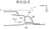
Suppose that shown in Fig. 7 A and Fig. 7 B when the secondary collision of passenger F took place, folder wall portion 102 was out of shape by press-bending because of the impact load that is input to folder mounting base 100 and to the interior lateral buckling in closed section zone 104.In this case, although not shown, folder wall portion 102 becomes and is in two part in the closed section zone 104 and is stacked on state between Door Trim 106 and the folder arrangement portion 108.Thereby the impact stroke of folder wall portion 102 has reduced the amount corresponding with the thickness of two parts of pressing from both sides wall portion 102, thereby has stoped Door Trim 106 distortion to accelerate the end of distortion thus.
But, according to present embodiment, as shown in Figure 6A, be arranged on kink 67 in the folder wall portion 66 to the outer lateral buckling (having angle thus) in the closed section zone 65 of folder mounting base 54.In this case, shown in Fig. 6 B and Fig. 6 C, when the secondary collision owing to passenger F made that impact load is input to folder mounting base 54, folder wall portion 66 was out of shape by press-bending and presss from both sides wall portion 66 to the outer lateral buckling in closed section zone 65.
Thereby, can between Door Trim 16 and folder arrangement portion 64, guarantee the impact stroke of setting at design phase.That is to say that the kink 67 in the folder wall portion 66 has been configured to provide the initial point of the bending of pressing from both sides wall portion 66 in order to stablize the press-bending deformation pattern.Therefore, can effectively weaken the collision antagonistic force during with the Door Trim secondary collision in side collision as passenger F.Simultaneously, the angle θ that can depend on kink 67 comes the press-bending load of adjustable clamp wall portion 66 easily.
As shown in Figure 5, vertical wall portion 66A extends internally and extends forward for vehicle from the end of the folder arrangement portion 64 of folder wall portion 66 at vehicle-width direction, and rake 66B extends internally and extends forward for vehicle at vehicle-width direction from vertical wall portion 66A.Kink 67 is formed between rake 66B and the vertical wall portion 66A.
Thereby kink 67 is positioned in inboard on the vehicle-width direction with respect to folder arrangement portion 64 and for the place ahead of vehicle.That is to say that kink 67 does not have the power application point, and be input to folder during mounting base 54 when impact load that the moment M that points to the vehicle-width direction outside occurs among the vertical wall portion 66A, around the end of folder arrangement portion 64.As a result, press from both sides wall portion 66 outside distortion to closed section zone 65 by bending.Thereby, can further stablize the press-bending deformation pattern.
Shown in Fig. 6 A to Fig. 6 C, along with 54 distortion of folder mounting base and whereabouts, absorb impact energy, effectively weaken the collision antagonistic force that passenger F receives thus.Based on this reason, according to present embodiment, vertical wall portion 66A and rake 66B are along with they turn forward for vehicle near kink 67.
Although owing to the secondary collision of passenger F makes Door Trim 16 be out of shape, Door Trim 16, produce tension force towards the general 18B of portion from the 18A of wall portion owing to the distortion of Door Trim 16 herein, in wide zone.Folder mounting base 54 be arranged on Door Trim 16 for the posterior region of vehicle the time, tension force T1 mainly is created on the forward direction of vehicle.
Thereby, according to present embodiment, forming the situation that is parallel to vehicle-width direction with vertical wall portion 66A or rake 66B and compare, folder mounting base 54 is easier to be out of shape because of the tension force T1 that produces in the Door Trim 16.That is to say, use tension force Tl to allow folder mounting base 54 to fall.Simultaneously much less, vertical wall portion 66A or rake 66B can form certainly and be parallel to vehicle-width direction.
Therefore, folder mounting base 54 is influenced by tension force T1 easily.That is to say, when producing tension force T1 in the Door Trim 16, thus 54 distortion of folder mounting base and the absorption impact energy that falls.As a result, can effectively weaken the collision antagonistic force that passenger F receives.
As shown in Figure 5, end difference 58 be formed on basic panel 18 the general 18B of portion the 18A of wall portion side in case on the longitudinal direction of vehicle setback, and sagging portion 60,62 be arranged to the compartment 22 interior side-prominent.Thereby shown in Fig. 6 A to Fig. 6 C, when folder mounting base 54 fell, the tension force among the general 18B of portion of Door Trim 16 stretched to weaken in sagging portion 60,62.That is to say that folder mounting base 54 becomes and further is easy to, and relaxes the impact that passenger F receives thus.
(modification of folder mounting base)
As shown in Figure 5, Door Trim 16 is mounted to an inner panel 24 via folder 56.When folder 56 is installed in the mounting hole 52, usually, will presss from both sides 56 and be pressed into mounting hole 52.For this purpose, folder mounting base 54 need have and can bear the rigidity that folder 56 is pressed into thrust (axial force) N of the mounting hole 52 in the inner panel 24.
Thereby according to present embodiment, shown in Fig. 8 A, rib 78 extends to under-vehicle from folder wall portion 66, and rib 78 is set to one with the general 18B of portion of basic panel 18.Rib 78 has triangular shapedly when seeing along the longitudinal direction of vehicle, and is shaped to from folder arrangement portion 64 sides and expands gradually towards the general 18B of portion.
As a result, as shown in Figure 5, when the folder 56 on the folder mounting base 54 is pressed into mounting hole 52, can be reduced in the contact pressure of importing on the vehicle-width direction based on axial force N, weaken the stress that produces in the folder mounting base 54 thus.
When folder 56 is installed in the mounting hole 52, shown in Fig. 9 A and Fig. 9 B, at the vertical direction generation tension force T2 of the vehicle that presss from both sides mounting base 54, T3.Because folder mounting base 54 is disposed in the upside with respect to vehicle of Door Trim 16, so the tension force T2 that the tension force T3 that the downward direction of vehicle produces in folder mounting base 54 produces greater than the upward direction at vehicle.Thereby, can prevent from pressing from both sides mounting base 54 from the folder wall portion 66 of pressing from both sides mounting base 54 to the outstanding rib 78 of under-vehicle and be damaged, prevent the distortion that causes because of the press-bending of pressing from both sides mounting base 54 thus.
Because outstanding from the folder wall portion 66 of folder mounting base 54 with the integrally formed rib 78 of the general 18B of portion, so the amount corresponding with the rib that provides according to this modification 78 has been provided in the zone of folder wall portion 66 in the folder mounting base 54.Thereby, see Fig. 6 A when the forward direction at vehicle applies tension force T1() time, along with the distortion of the general 18B of portion, folder wall portion 66 becomes and is easier to, and further is beneficial to the distortion of folder mounting base 54 thus.
Although described as shown in Figure 5 when folder 56 is pressed into mounting hole 52, input to the folder mounting base 54 axial force N import at vehicle-width direction, depend on the shape of Door Trim 16, axial force N can with the oblique input of vehicle-width direction.In this case, from the angle of the rigidity of guaranteeing to press from both sides mounting base 54, it is perhaps better that rib 78 is arranged on folder arrangement portion 61 sides.
Although shown in Fig. 8 A, rib 78 is outstanding downwards for vehicle from the folder wall portion 66 of folder mounting base 54, rib can project upwards for vehicle.Because folder mounting base 54 is arranged on the upside for vehicle, so as mentioned above, the tension force T2 that the tension force T3 that the downward direction of vehicle produces in folder mounting base 54 produces greater than the upward direction at vehicle.Thereby, be out of shape greatlyyer with respect to folder mounting base 54 at the Door Trim 16 of vehicle lower side.Thereby, more effective for the distortion of folder mounting base 54 to the outstanding rib 78 of under-vehicle from folder wall portion 66 sides.
In addition, shown in Fig. 8 B, can be provided with strut member 84 at the connecting portion (spine) 80 between the general 18B of portion of the folder folder wall portion 66 of mounting base 54 and basic panel 18 or the connecting portion 82 between the 18A of wall portion of the folder arrangement portion 64 of folder mounting base 54 and basic panel 18, its longitudinal direction along vehicle is arranged in the inboard of folder mounting base 54 to strengthen connecting portion 80,82.
Therefore, see Fig. 5 when Door Trim 16 is mounted to an inner panel 24() time, the press-bending distortion that can suppress to press from both sides mounting base 54.Although for the convenience of mapping is shown strut member 84 at the downside of connecting portion 82 for vehicle, but, if strut member 84 is arranged on the central portion on the vertical direction of vehicle of connecting portion 82, then strut member 84 enters mounting hole 64A or patchhole 69 when folder mounting base 54 falls, and can not hinder the whereabouts of folder mounting base 54 thus.
(replenishing of present embodiment)
Usually, when contacting Door Trim 16 as the secondary collision passenger, because the passenger is sitting on the seat, so the height at the regional A place of Door Trim 16 as shown in Figure 2 is corresponding to the position of passenger's chest.Thereby, in the regional A of Door Trim 16, comprise that according to the basic panel 18 of present embodiment the configuration of pressing from both sides mounting base 54 has effectively weakened the collision antagonistic force that passenger's chest receives from Door Trim 16.Much less, except Door Trim 16 for the regional A in the posterior region of vehicle, basic panel 18 comprises that the configuration of pressing from both sides mounting base 54 can certainly be applied to other zones of Door Trim 16.
In addition, although as shown in Figure 5, according to present embodiment, Door Trim 16 is formed by basic panel 18 and decoration panel 20, and Door Trim 16 can be by with basic panel 18 and decoration panel 20 Unitarily molded formation.
In addition, although according to present embodiment, folder mounting base 54 forms and makes that folder mounting base 54 is L shaped along the cross sectional shape of the longitudinal direction intercepting of vehicle, but folder mounting base 54 can be Any shape, needs only and presss from both sides mounting base 54 whereabouts when the load that applies when the longitudinal direction along vehicle is input to Door Trim 16.Thereby the cross sectional shape of folder mounting base 54 must not be L shaped.
Although illustrate and described pivot type side door 12 in the present embodiment, the present invention can be applied to the sliding-type side door.
Although more than described one embodiment of the present of invention, the invention is not restricted to above-mentioned example.Much less, the present invention can certainly be embodied as various distortion and not depart from its main points in its scope.
Claims (8)
1. Door Trim that is used for vehicle is characterized in that comprising:
Plaque main body (16), it forms inboard bulging towards the compartment as the interior material of the door inner panel (24) of side door (12); And
Folder mounting base (54), it is arranged in the posterior region for described vehicle on the described plaque main body (16), and described folder mounting base (54) comprising:
Folder arrangement portion (64), its be configured to described door inner panel (24) in opposite directions, and be equipped with folder, described folder is installed in the mounting hole that is formed in the described door inner panel (24); And
Folder wall portion (66), it is set to described folder arrangement portion (64) continuous, and under described Door Trim is installed in state in the described vehicle, form closed section portion in folder wall portion and described plaque main body (16) and described folder arrangement portion (64) described in the horizontal section, described folder wall portion (66) comprises kink, and described kink has angle so that protrudes outside described closed section portion.
2. Door Trim according to claim 1, wherein
Described folder mounting base is arranged in the upper-side area for described vehicle on the described plaque main body.
3. Door Trim according to claim 1 and 2, wherein
Described plaque main body comprises: the general portion of plaque (18B), and it forms the plaque design surface; And plaque wall portion (18A), it is arranged on the periphery of the general portion of described plaque (18B) and outwards erects on vehicle-width direction,
Described folder arrangement portion stretches out from described plaque wall portion (18A), and
Described folder wall portion is arranged in the place ahead for described vehicle of described plaque wall portion (18A), and forms continuously with the general portion of described plaque (18B).
4. Door Trim according to claim 3, wherein
Form along the end difference (58) of longitudinal direction of car direction setback and be arranged on connecting portion place between the general portion of described plaque and the described plaque wall portion, and
Described end difference (58) comprises the described inboard sagging portion (60,62) of protruding towards described compartment.
5. Door Trim according to claim 1 and 2, wherein
Described folder wall portion comprises:
Vertical wall portion (66A), inwardly and for described vehicle extend forward on vehicle-width direction its end from described folder arrangement portion; And
Rake (66B), its described kink place and described vertical wall portion (66A) angulation be connected to described vertical wall portion (66A), and described rake inwardly and for described vehicle extends forward on described vehicle-width direction from described kink.
6. Door Trim according to claim 5, wherein
Described rake with respect to the angle of described folder arrangement portion than described vertical wall portion with respect to the angle of described folder arrangement portion more near 90 °.
7. Door Trim according to claim 1 and 2, wherein
The angle of described kink is greater than 90 ° and less than 180 °.
8. Door Trim according to claim 7, wherein
The angle of described kink is greater than 120 ° and less than 170 °.
Applications Claiming Priority (2)
| Application Number | Priority Date | Filing Date | Title |
|---|---|---|---|
| JP2012004127A JP5899937B2 (en) | 2012-01-12 | 2012-01-12 | Mounting structure for automotive door trim |
| JP2012-004127 | 2012-01-12 |
Publications (2)
| Publication Number | Publication Date |
|---|---|
| CN103204111A true CN103204111A (en) | 2013-07-17 |
| CN103204111B CN103204111B (en) | 2015-09-02 |
Family
ID=48751586
Family Applications (1)
| Application Number | Title | Priority Date | Filing Date |
|---|---|---|---|
| CN201310010279.7A Expired - Fee Related CN103204111B (en) | 2012-01-12 | 2013-01-10 | Vehicle Door Trim |
Country Status (3)
| Country | Link |
|---|---|
| US (1) | US8801075B2 (en) |
| JP (1) | JP5899937B2 (en) |
| CN (1) | CN103204111B (en) |
Cited By (2)
| Publication number | Priority date | Publication date | Assignee | Title |
|---|---|---|---|---|
| CN107804244A (en) * | 2016-09-08 | 2018-03-16 | 福特全球技术公司 | Use the pelvis load management of the integrated crushable structures in door trim |
| CN108297656A (en) * | 2017-01-13 | 2018-07-20 | 通用汽车环球科技运作有限责任公司 | Postpone vehicle inside door when for side collision and adorns the system and method being detached from from the metallic plate of door |
Families Citing this family (12)
| Publication number | Priority date | Publication date | Assignee | Title |
|---|---|---|---|---|
| US9382732B2 (en) * | 2011-01-21 | 2016-07-05 | GM Global Technology Operations LLC | Door assembly with anti-theft device |
| US8985674B2 (en) * | 2011-08-02 | 2015-03-24 | Toyota Boshoku Kabushiki Kaisha | Door trim for vehicle |
| US8979156B2 (en) * | 2013-03-22 | 2015-03-17 | Nissan North America, Inc. | Vehicle panel attachment arrangement |
| JP6052029B2 (en) * | 2013-04-04 | 2016-12-27 | トヨタ紡織株式会社 | Interior materials for vehicles |
| US9174586B2 (en) * | 2013-11-08 | 2015-11-03 | Nyx, Inc. | Storage compartment apparatus for door of a vehicle |
| CN103640528B (en) * | 2013-12-13 | 2015-09-30 | 宁波明佳汽车内饰有限公司 | Automobile door plate assembling chute buckle |
| KR101637303B1 (en) * | 2014-11-21 | 2016-07-07 | 현대자동차 주식회사 | Door structure for motor vehicle |
| US10406893B2 (en) * | 2016-06-29 | 2019-09-10 | GM Global Technology Operations LLC | Inner support panel for mounting a hardware module of a vehicle door assembly |
| JP6585015B2 (en) * | 2016-07-25 | 2019-10-02 | トヨタ紡織株式会社 | Interior materials for vehicles |
| US10145401B2 (en) * | 2017-01-26 | 2018-12-04 | Ford Global Technologies, Llc | Clip for a vehicle door assembly |
| US10780844B2 (en) * | 2018-06-27 | 2020-09-22 | Ford Global Technologies, Llc | Fastening system for securing a trim panel to a support substrate |
| JP7408252B2 (en) * | 2021-01-28 | 2024-01-05 | ダイハツ工業株式会社 | Vehicle interior parts |
Citations (3)
| Publication number | Priority date | Publication date | Assignee | Title |
|---|---|---|---|---|
| US6126230A (en) * | 1996-12-24 | 2000-10-03 | Toyota Jidosha Kabushiki Kaisha | Energy absorbing structure for automobile |
| CN101795904A (en) * | 2007-10-11 | 2010-08-04 | 丰田自动车株式会社 | Vehicle inner panel |
| JP2011126489A (en) * | 2009-12-21 | 2011-06-30 | Toyota Motor Corp | Door trim mounting structure and door trim |
Family Cites Families (12)
| Publication number | Priority date | Publication date | Assignee | Title |
|---|---|---|---|---|
| JP2548057Y2 (en) * | 1991-07-09 | 1997-09-17 | 日産自動車株式会社 | Automotive door trim mounting structure |
| US5169204A (en) * | 1992-04-08 | 1992-12-08 | Davidson Textron Inc. | Energy absorbing inner door panel with fasteners to absorb body impact energy |
| JP3435866B2 (en) * | 1994-12-27 | 2003-08-11 | 日産自動車株式会社 | Automotive side trim mounting structure |
| US6149224A (en) * | 1999-06-11 | 2000-11-21 | Delphi Technologies, Inc. | Break away trim panel assembly |
| JP3633537B2 (en) * | 2001-09-27 | 2005-03-30 | トヨタ自動車株式会社 | Mounting structure for interior parts for vehicles |
| JP2006069347A (en) * | 2004-09-01 | 2006-03-16 | Kasai Kogyo Co Ltd | Installation structure of shock absorbing pad |
| JP2008120128A (en) | 2006-11-08 | 2008-05-29 | Kasai Kogyo Co Ltd | Clip mounting seat structure |
| JP5125545B2 (en) | 2008-01-25 | 2013-01-23 | トヨタ紡織株式会社 | Clip seat mounting structure and door trim mounting structure |
| US7726726B2 (en) * | 2008-02-19 | 2010-06-01 | Gm Global Technology Operations, Inc. | Energy-absorbing system for vehicle door assembly |
| US7677640B2 (en) * | 2008-05-23 | 2010-03-16 | Nissan Technical Center North America, Inc. | Panel assembly for a vehicle |
| JP2010264971A (en) * | 2009-04-14 | 2010-11-25 | Toyota Boshoku Corp | Mounting structure of resin impact absorber for side impact |
| US8020921B2 (en) * | 2009-08-17 | 2011-09-20 | Toyota Motor Engineering & Manufacturing North America, Inc. | Door trim panel having temporary support and pivot members and method of installing the door trim panel |
-
2012
- 2012-01-12 JP JP2012004127A patent/JP5899937B2/en active Active
-
2013
- 2013-01-10 US US13/738,369 patent/US8801075B2/en active Active
- 2013-01-10 CN CN201310010279.7A patent/CN103204111B/en not_active Expired - Fee Related
Patent Citations (3)
| Publication number | Priority date | Publication date | Assignee | Title |
|---|---|---|---|---|
| US6126230A (en) * | 1996-12-24 | 2000-10-03 | Toyota Jidosha Kabushiki Kaisha | Energy absorbing structure for automobile |
| CN101795904A (en) * | 2007-10-11 | 2010-08-04 | 丰田自动车株式会社 | Vehicle inner panel |
| JP2011126489A (en) * | 2009-12-21 | 2011-06-30 | Toyota Motor Corp | Door trim mounting structure and door trim |
Cited By (4)
| Publication number | Priority date | Publication date | Assignee | Title |
|---|---|---|---|---|
| CN107804244A (en) * | 2016-09-08 | 2018-03-16 | 福特全球技术公司 | Use the pelvis load management of the integrated crushable structures in door trim |
| CN107804244B (en) * | 2016-09-08 | 2023-08-25 | 福特全球技术公司 | Pelvis load management with integrated crushable structure in door trim |
| CN108297656A (en) * | 2017-01-13 | 2018-07-20 | 通用汽车环球科技运作有限责任公司 | Postpone vehicle inside door when for side collision and adorns the system and method being detached from from the metallic plate of door |
| CN108297656B (en) * | 2017-01-13 | 2021-07-13 | 通用汽车环球科技运作有限责任公司 | System and method for delaying detachment of interior door trim of vehicle in case of side collision |
Also Published As
| Publication number | Publication date |
|---|---|
| JP2013141944A (en) | 2013-07-22 |
| US20130181475A1 (en) | 2013-07-18 |
| JP5899937B2 (en) | 2016-04-06 |
| CN103204111B (en) | 2015-09-02 |
| US8801075B2 (en) | 2014-08-12 |
Similar Documents
| Publication | Publication Date | Title |
|---|---|---|
| CN103204111A (en) | Vehicle Door Trim | |
| US7144055B2 (en) | Vehicle body frontal structure | |
| CN105473424B (en) | The frame structure of vehicle | |
| EP2881308B1 (en) | Shock absorption member | |
| US8939479B2 (en) | Vehicle bumper | |
| CN103459881B (en) | There is the motor vehicle bumper of the pedestrian protection system of integration | |
| JP2014024465A (en) | Vehicle front part structure | |
| US20080203763A1 (en) | Vehicle front structure | |
| CN102452424A (en) | Frame for vehicle | |
| JP5139954B2 (en) | Bumper device for vehicle | |
| JP2010116074A (en) | Vehicle hood structure | |
| CN107972742A (en) | Supporting member | |
| CN113811459B (en) | Buffer member for vehicle | |
| CN106458121B (en) | Automobile structural member | |
| CN209972590U (en) | Dash panel and vehicle | |
| JP4036219B2 (en) | Automotive engine hood structure | |
| US10407105B2 (en) | Vehicle lateral structure | |
| CN205396229U (en) | Fender installing support and vehicle fender installation assembly | |
| JP5095285B2 (en) | Shock absorbing structure and automobile door | |
| US20120292947A1 (en) | Vehicle collision load transmission structure | |
| CN110958970A (en) | Front structure of vehicle | |
| KR20110051594A (en) | Crash box in automotive bumper system | |
| CN112092701B (en) | Head rest | |
| KR101272034B1 (en) | Reinforced structure of FEM carrier | |
| JP2001278118A (en) | Fender structure of vehicle |
Legal Events
| Date | Code | Title | Description |
|---|---|---|---|
| C06 | Publication | ||
| PB01 | Publication | ||
| C10 | Entry into substantive examination | ||
| SE01 | Entry into force of request for substantive examination | ||
| C14 | Grant of patent or utility model | ||
| GR01 | Patent grant | ||
| C53 | Correction of patent of invention or patent application | ||
| CI03 | Correction of invention patent |
Correction item: Claims Correct: Correct False: Error Number: 35 Page: Description Volume: 31 |
|
| CF01 | Termination of patent right due to non-payment of annual fee |
Granted publication date: 20150902 |
|
| CF01 | Termination of patent right due to non-payment of annual fee |