CN103164003A - Electronic device heat dissipating system - Google Patents
Electronic device heat dissipating system Download PDFInfo
- Publication number
- CN103164003A CN103164003A CN201110423344XA CN201110423344A CN103164003A CN 103164003 A CN103164003 A CN 103164003A CN 201110423344X A CN201110423344X A CN 201110423344XA CN 201110423344 A CN201110423344 A CN 201110423344A CN 103164003 A CN103164003 A CN 103164003A
- Authority
- CN
- China
- Prior art keywords
- fan module
- ventilation slot
- gas channel
- plugboard
- electronic component
- Prior art date
- Legal status (The legal status is an assumption and is not a legal conclusion. Google has not performed a legal analysis and makes no representation as to the accuracy of the status listed.)
- Granted
Links
Images
Landscapes
- Cooling Or The Like Of Electrical Apparatus (AREA)
Abstract
Description
| |
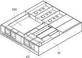
10 |
| Base plate | 11 |
| Mainboard | 20 |
| The first |
25 |
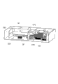
| Plugboard | 30 |
| The |
32 |
| The second ventilation slot | 34 |
| |
36 |
| The first fan module | 40 |
| The |
45 |
| The second electronic component | 50 |
| The 3rd electronic component | 60 |
| |
200 |
| Baffle plate | 210 |
| The first dividing plate | 220 |
| Second partition | 230 |
| Fixed head | 240 |
| The |
250 |
| The |
260 |
| The |
270 |
| The |
280 |
Claims (9)
Priority Applications (1)
| Application Number | Priority Date | Filing Date | Title |
|---|---|---|---|
| CN201110423344.XA CN103164003B (en) | 2011-12-16 | 2011-12-16 | Heat radiation system of electronic device |
Applications Claiming Priority (1)
| Application Number | Priority Date | Filing Date | Title |
|---|---|---|---|
| CN201110423344.XA CN103164003B (en) | 2011-12-16 | 2011-12-16 | Heat radiation system of electronic device |
Publications (2)
| Publication Number | Publication Date |
|---|---|
| CN103164003A true CN103164003A (en) | 2013-06-19 |
| CN103164003B CN103164003B (en) | 2016-08-17 |
Family
ID=48587156
Family Applications (1)
| Application Number | Title | Priority Date | Filing Date |
|---|---|---|---|
| CN201110423344.XA Expired - Fee Related CN103164003B (en) | 2011-12-16 | 2011-12-16 | Heat radiation system of electronic device |
Country Status (1)
| Country | Link |
|---|---|
| CN (1) | CN103164003B (en) |
Cited By (8)
| Publication number | Priority date | Publication date | Assignee | Title |
|---|---|---|---|---|
| CN108089678A (en) * | 2017-12-25 | 2018-05-29 | 曙光信息产业(北京)有限公司 | A kind of server air guiding cover heat radiation module |
| CN109413933A (en) * | 2017-08-18 | 2019-03-01 | 鸿富锦精密工业(武汉)有限公司 | Plug connector fixed structure and electronic device |
| CN109960380A (en) * | 2017-12-22 | 2019-07-02 | 鸿富锦精密电子(天津)有限公司 | Wind scooper, cabinet and electronic device using the wind scooper |
| WO2020107450A1 (en) * | 2018-11-30 | 2020-06-04 | 北京比特大陆科技有限公司 | Data processing apparatus |
| CN111367370A (en) * | 2018-12-26 | 2020-07-03 | 鸿富锦精密工业(武汉)有限公司 | Electronic device |
| CN113056179A (en) * | 2021-03-31 | 2021-06-29 | 联想(北京)有限公司 | Electronic equipment |
| CN113576274A (en) * | 2021-07-23 | 2021-11-02 | 广东美的厨房电器制造有限公司 | Door body and cooking device |
| TWI838973B (en) * | 2022-11-22 | 2024-04-11 | 神雲科技股份有限公司 | server |
Citations (3)
| Publication number | Priority date | Publication date | Assignee | Title |
|---|---|---|---|---|
| US20070091564A1 (en) * | 2005-10-25 | 2007-04-26 | Malone Christopher G | Air duct with airtight seal |
| US20080123292A1 (en) * | 2006-11-27 | 2008-05-29 | Dell Products L.P. | Reinforced Air Shroud |
| CN201174851Y (en) * | 2008-04-02 | 2008-12-31 | 英业达股份有限公司 | Wind guiding cover |
-
2011
- 2011-12-16 CN CN201110423344.XA patent/CN103164003B/en not_active Expired - Fee Related
Patent Citations (3)
| Publication number | Priority date | Publication date | Assignee | Title |
|---|---|---|---|---|
| US20070091564A1 (en) * | 2005-10-25 | 2007-04-26 | Malone Christopher G | Air duct with airtight seal |
| US20080123292A1 (en) * | 2006-11-27 | 2008-05-29 | Dell Products L.P. | Reinforced Air Shroud |
| CN201174851Y (en) * | 2008-04-02 | 2008-12-31 | 英业达股份有限公司 | Wind guiding cover |
Cited By (11)
| Publication number | Priority date | Publication date | Assignee | Title |
|---|---|---|---|---|
| CN109413933A (en) * | 2017-08-18 | 2019-03-01 | 鸿富锦精密工业(武汉)有限公司 | Plug connector fixed structure and electronic device |
| CN109960380A (en) * | 2017-12-22 | 2019-07-02 | 鸿富锦精密电子(天津)有限公司 | Wind scooper, cabinet and electronic device using the wind scooper |
| CN108089678A (en) * | 2017-12-25 | 2018-05-29 | 曙光信息产业(北京)有限公司 | A kind of server air guiding cover heat radiation module |
| CN108089678B (en) * | 2017-12-25 | 2020-11-03 | 中科曙光信息产业成都有限公司 | Server wind scooper heat dissipation module |
| WO2020107450A1 (en) * | 2018-11-30 | 2020-06-04 | 北京比特大陆科技有限公司 | Data processing apparatus |
| CN111367370A (en) * | 2018-12-26 | 2020-07-03 | 鸿富锦精密工业(武汉)有限公司 | Electronic device |
| CN111367370B (en) * | 2018-12-26 | 2022-07-29 | 鸿富锦精密工业(武汉)有限公司 | Electronic device |
| CN113056179A (en) * | 2021-03-31 | 2021-06-29 | 联想(北京)有限公司 | Electronic equipment |
| CN113576274A (en) * | 2021-07-23 | 2021-11-02 | 广东美的厨房电器制造有限公司 | Door body and cooking device |
| CN113576274B (en) * | 2021-07-23 | 2023-08-18 | 广东美的厨房电器制造有限公司 | Door body and cooking device |
| TWI838973B (en) * | 2022-11-22 | 2024-04-11 | 神雲科技股份有限公司 | server |
Also Published As
| Publication number | Publication date |
|---|---|
| CN103164003B (en) | 2016-08-17 |
Similar Documents
| Publication | Publication Date | Title |
|---|---|---|
| CN103164003A (en) | Electronic device heat dissipating system | |
| US8913382B2 (en) | Server | |
| CN102436298B (en) | Heat dissipation equipment and blade server | |
| CN101257780B (en) | Wind-guiding apparatus of electronic equipment | |
| US20110317359A1 (en) | Fan duct for electronic components of electronic device | |
| CN201600636U (en) | Shell of electronic device | |
| CN203104252U (en) | Novel heat radiation structure | |
| CN204578961U (en) | Radiator structure and there is the electronic installation of this radiator structure | |
| US20160098068A1 (en) | Computer case providing multiple independent airflows | |
| CN102445967A (en) | Server case | |
| CN201226633Y (en) | Electronic device with radiating system | |
| CN104812222A (en) | Heat dissipation structure and electronic device comprising same | |
| EP2071910B1 (en) | Method of heat dissipating for plug-in boxes in cabinet and air-guiding apparatus | |
| TW201408179A (en) | Airflow guiding member and electronic device having the same | |
| CN104142717A (en) | Electronic device and air guide cover thereof | |
| CN108932039A (en) | Wind scooper and cooling system | |
| TW201328553A (en) | Heat dissipation system for electronic device | |
| CN202561920U (en) | Electric appliance box of air conditioner outdoor unit and air conditioner outdoor unit with same | |
| CN102854945A (en) | Electronic device | |
| CN107087383B (en) | Air quantity adjusting plate for plug box and application method thereof | |
| US20150049435A1 (en) | Electronic device | |
| CN103135719A (en) | Electronic device | |
| TW201325413A (en) | Electronic device and fan duct of the same | |
| CN104717869B (en) | Electronic installation and its heat radiation module | |
| CN102469742A (en) | Electronic device |
Legal Events
| Date | Code | Title | Description |
|---|---|---|---|
| C06 | Publication | ||
| PB01 | Publication | ||
| C10 | Entry into substantive examination | ||
| SE01 | Entry into force of request for substantive examination | ||
| C41 | Transfer of patent application or patent right or utility model | ||
| TA01 | Transfer of patent application right |
Effective date of registration: 20160201 Address after: 528437 Guangdong province Zhongshan Torch Development Zone, Cheung Hing Road 6 No. 222 north wing trade building room Applicant after: Zhongshan yunchuang Intellectual Property Service Co.,Ltd. Address before: 518109 Guangdong province Shenzhen city Longhua District Dragon Road No. 83 wing group building 11 floor Applicant before: SCIENBIZIP CONSULTING (SHEN ZHEN) Co.,Ltd. Effective date of registration: 20160201 Address after: 518109 Guangdong province Shenzhen city Longhua District Dragon Road No. 83 wing group building 11 floor Applicant after: SCIENBIZIP CONSULTING (SHEN ZHEN) Co.,Ltd. Address before: 518109 Guangdong city of Shenzhen province Baoan District Longhua Town Industrial Zone tabulaeformis tenth East Ring Road No. 2 two Applicant before: HONG FU JIN PRECISION INDUSTRY (SHENZHEN) Co.,Ltd. Applicant before: HON HAI PRECISION INDUSTRY Co.,Ltd. |
|
| C41 | Transfer of patent application or patent right or utility model | ||
| CB03 | Change of inventor or designer information |
Inventor after: Wang Ruining Inventor after: Dongyang in Sui Dynasty Inventor after: Wang Zhenhai Inventor after: Wang Wenwen Inventor after: Xu Mingwei Inventor after: Wang Peng Inventor after: Zhang Xuying Inventor after: Sun Anfeng Inventor after: Fang Lei Inventor after: Jiang Guang Inventor after: Jin Zhiqiang Inventor after: Wang Jun Inventor before: Lin Daiwei Inventor before: Chen Jinhui |
|
| COR | Change of bibliographic data | ||
| TA01 | Transfer of patent application right |
Effective date of registration: 20160713 Address after: Dongguan Street in Zhucheng City in Shandong province Weifang City No. 2 262200 Applicant after: ZHUCHENG CITY POWER SUPPLY COMPANY, STATE GRID SHANDONG ELECTRIC POWER CO. Applicant after: STATE GRID SHANDONG ELECTRIC POWER COMPANY WEIFANG POWER SUPPLY Co. Applicant after: State Grid Corporation of China Address before: 528437 Guangdong province Zhongshan Torch Development Zone, Cheung Hing Road 6 No. 222 north wing trade building room Applicant before: Zhongshan yunchuang Intellectual Property Service Co.,Ltd. |
|
| C14 | Grant of patent or utility model | ||
| GR01 | Patent grant | ||
| CF01 | Termination of patent right due to non-payment of annual fee |
Granted publication date: 20160817 Termination date: 20171216 |
|
| CF01 | Termination of patent right due to non-payment of annual fee |