CN103074829A - Railway switch changing construction method and railway switch track laying unit thereof - Google Patents
Railway switch changing construction method and railway switch track laying unit thereof Download PDFInfo
- Publication number
- CN103074829A CN103074829A CN2013100029984A CN201310002998A CN103074829A CN 103074829 A CN103074829 A CN 103074829A CN 2013100029984 A CN2013100029984 A CN 2013100029984A CN 201310002998 A CN201310002998 A CN 201310002998A CN 103074829 A CN103074829 A CN 103074829A
- Authority
- CN
- China
- Prior art keywords
- main frame
- laying
- frame
- outfit
- track
- Prior art date
- Legal status (The legal status is an assumption and is not a legal conclusion. Google has not performed a legal analysis and makes no representation as to the accuracy of the status listed.)
- Granted
Links
Images


Landscapes
- Machines For Laying And Maintaining Railways (AREA)
Abstract
The invention discloses a railway switch changing construction method and a railway switch track laying unit thereof. The track laying unit comprises a main machine, an auxiliary machine and a hydraulic reloading frame; the main machine comprises a main machine flat car, an arm, a front vertical column gantry structure, a rear vertical column gantry structure, a lifting trolley, a hoisting mechanism and a running mechanism; the auxiliary machine at least comprises an auxiliary machine flat car; and the hydraulic reloading frame comprises a first reloading frame, a second reloading frame and a reloading hanger. The railway switch track laying unit solves the problems that traditional manual laying or changing can easily cause permanent distortion of steel rails or fittings of switches or cause the laying accuracy not to meet the requirements, and speed-raising turnouts are required to be assembled in a factory block by block and integrally laid in the field, realizes mechanical switch changing and laying, increases the speed, improves the efficiency, reduces the cost, and can also further improve the laying quality and the safety performance.
Description
Technical field
The present invention relates to railway switch that track traffic laying a switch or the section of track use and change and spread engineering method and railway switch thereof the unit of laying a railway track, especially relate to railway switch for switch replacement and laying and change and spread engineering method and railway switch thereof the unit of laying a railway track.
Background technology
Railway switch is a kind of line connection equipment that makes rolling stock change another station track over to from a station track, and railway switch usually AT STATION, marshalling yard lays in a large number.
The mechanization of track switch is laid on the developed countries such as Austria, Finland, France and has realized, there is WM500U type track switch laydown machine in Austria, and there is TL50 type track switch laydown machine in Finland, and there is PEM/LEM type track switch laydown machine in France.
The switch changing and laying of China changes at present or take traditional manual method and spreads as main, has a Field Force many, and blocking time is long, difficulty of construction is large, lay not high of precision, also easily cause the switch parts permanent deformation, can not adapt to the requirement of present railway speed increase development.
Along with China railways develops fast, railway switch also constantly is replaced by acclerating road switch, laying requirement to track switch is more and more higher, lays and change easily to cause rail and accessory permanent deformation or lay precision with Traditional Man not reach requirement, and piecemeal is assembled in the acclerating road switch requirement factory.The domestic installation apparatus that also is not specifically designed to railway switch is studied new switch changing and laying construction technology and is equipped extremely urgent.
My company is engaged in for a long time rail-mounted shop and sets up standby development, accumulating rich experience aspect the frame construction technology of railway shop, my company changes the shop technology to railway switch and studies for this reason, find no matter be future trend or construction needs, when switch replacement and laying, adopt mechanization to lay the road that is inevitable, laying acclerating road switch by mechanization also is the inevitable of railway development, therefore, in order to improve China's road maintainance machinery equipment, create favorable conditions for improve the circuit homework quality comprehensively, need the unit of laying a railway track of the brand-new work pattern of exploitation switch replacement and laying, the research success of this equipment will remedy domestic and international blank.
For this reason, designer of the present invention is because defects by concentrating on studies and designing, comprehensively is engaged in for a long time experience and the achievement of related industry for many years, research and design goes out a kind of railway switch changes and spreads engineering method and railway switch thereof the unit of laying a railway track, to overcome the defective of prior art.
Summary of the invention
The object of the present invention is to provide a kind of railway switch to change to spread engineering method and railway switch thereof the unit of laying a railway track, it will solve the Traditional Man laying and change rail and the accessory permanent deformation that easily causes track switch or lay precision and not reach requirement, acclerating road switch requires piecemeal assembling in the factory, on-the-spot whole problem of laying, realized that mechanization carries out switch replacement and laying, improve speed and efficient, reduced cost, can also further improve laying quality and security performance.
For achieving the above object, the invention discloses a kind of railway switch unit of laying a railway track, this unit of laying a railway track comprises main frame, subsidiary engine and the hydraulic pressure frame three parts that change the outfit, and it is characterized in that:
This main frame includes main frame flatcar, horn, front column gantry structure, rear column gantry structure, trolley, hoisting mechanism and running mechanism, horn is arranged on this main frame flatcar by front column gantry structure and rear column gantry structure, have the track that moves forward and backward for trolley on the horn thereon, hoisting mechanism and running mechanism are arranged at the rear end of horn;
This subsidiary engine includes the subsidiary engine flatcar at least;
This hydraulic pressure frame that changes the outfit comprises the first change the outfit frame, second change the outfit frame and suspender that changes the outfit, and this suspender that changes the outfit is dismountable to be fixed in this first frame and second that changes the outfit and to change the outfit on the frame.
Wherein: this front column gantry structure is the identical shaped as frame of structure with the rear column gantry structure, include extending bracket, post root telescopic oil cylinder, the post root, the secondary shaft, the final stage shaft, stringer, the capital fixed cover, the capital movable sleeve, capital telescopic oil cylinder and shaft telescopic oil cylinder, the folding both sides of being fixed in this main frame flatcar of this extending bracket, this post root telescopic oil cylinder is 4 and with movable end being fixed on this main frame flatcar outwardly, be fixed in the lower end of post root at the movable end of this post root telescopic oil cylinder, this post root is that hollow structure is to form stretching structure with secondary shaft and final stage shaft, the end of two final stage shafts is fixedly connected with stringer, be provided with the shaft telescopic oil cylinder that can climb between the bottom platform of this stringer and post root, be provided with the capital fixed cover between the stringer of both sides, two capital telescopic oil cylinders are fixed in this capital fixed cover and the oil cylinder piston top is fixed with the capital movable sleeve, and the other end of this capital movable sleeve is fixed in stringer.
Wherein: below trolley, be provided with the hanger rail shoulder pole so that track switch or the section of track are lifted by crane.
Wherein: be respectively arranged with at front column gantry structure and rear column gantry structure and can realize swinging or the oscillating arm mechanisms of transverse moving left and right of horn, two cover oscillating arm mechanisms are arranged between the two column gantry structures.
Wherein: oscillating arm mechanisms includes wedge shape static line headstock, running block, swing arm oil cylinder, haulage cable, changed course pulley, clamped-in style static line headstock and chute.
Wherein: the main frame flatcar comprises brakes, hydraulic leg, five E axle framework type bogies, the traction running mechanism, the main frame car body, combined type four D axle bogie and coupler buffering devices, this brakes is positioned at the main frame Vehicular body front so that braking to be provided, this hydraulic leg lays respectively at the below of the front and rear part of main frame car body, this five E axle framework type bogie is positioned at below, main frame car body front side to carry out front end carrying and running, the rear side below that these combined type four D axle bogies are positioned at the main frame car body to be carrying out rear end carrying and running, this coupler buffering device be fixedly arranged on this main frame car body before, rear two ends are to provide marshalling to hang together.
Wherein: the subsidiary engine flatcar includes coupler buffering device, four E axle framework type bogies, traction running mechanism, subsidiary engine car body, combined type four D axle bogie and brakes, two coupler buffering devices lay respectively at the two ends of subsidiary engine car body, and four E axle framework type bogies and combined type four D axle bogies lay respectively at the both sides, front and back of subsidiary engine car body so that forward-and-rearward carrying and running to be provided.
The invention also discloses a kind of railway switch and change the shop engineering method, use the above-mentioned railway switch unit of laying a railway track to carry out switch changing and laying.
Pass through said structure, the railway switch of changing and laying for railway switch of the present invention changes and spreads engineering method and railway switch thereof the unit of laying a railway track, change artificial construction's engineering method in the past, reduced the construction operation personnel labor intensity, improved simultaneously quality and the safety of operation.The railway switch unit of laying a railway track is comprised of main frame, subsidiary engine and the hydraulic pressure frame three large parts that change the outfit, and the hydraulic pressure frame that changes the outfit is switched track switch or section of track group, and subsidiary engine transports track switch or section of track group, and main frame is finished laying or the recovery operation of track switch or the section of track.
The present invention will further describe in detail by the following specific embodiments, and will be more apparent and obvious to understand further combined with the description of the drawings.
Description of drawings
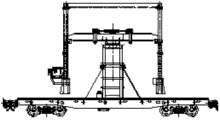
Fig. 1 has shown the schematic diagram of the main frame of railway track laying unit of the present invention.
Fig. 2 has shown the schematic diagram of the subsidiary engine of railway track laying unit of the present invention.
Fig. 3 has shown the change the outfit schematic diagram of frame of the hydraulic pressure of railway track laying unit of the present invention.
Fig. 4 has shown the elevation of column gantry structure of the present invention.
Fig. 5 has shown the lateral view of column gantry structure of the present invention.
Fig. 6 A-D has shown that column gantry structure of the present invention is the schematic diagram of duty from the travel position startup.
Fig. 7 has shown the structural representation of main frame flatcar of the present invention.
Fig. 8 A-C has shown the structural representation of oscillating arm mechanisms of the present invention.
Fig. 9 has shown the structural representation of subsidiary engine flatcar of the present invention.
Figure 10 has shown travel position schematic diagram of the present invention.
Figure 11 A-E has shown that the frame that changes the outfit of the present invention is the schematic diagram of duty from the travel position startup.
Figure 12 A-C has shown that subsidiary engine of the present invention packs suspender to the schematic diagram of the frame that changes the outfit.
Figure 13 has shown the work flow schematic diagram of acclerating road switch of the present invention.
Figure 14 A-H has shown the operation chart of railway track laying unit withdrawal railway switch of the present invention.
Figure 15 A-H has shown the operation chart that railway track laying unit of the present invention places an iron railway track switch.
Reference numeral:
1, main frame flatcar; 2, horn; 3, front column gantry structure; 4, rear column gantry structure; 5, trolley; 6, hanger rail shoulder pole; 7, oscillating arm mechanisms; 8, hoisting mechanism; 9, running mechanism; 11, main frame drivers' cab; 12, drag gear; 13, main frame electrical system; 14, host hydraulic system; 15, the automatic loopback of main frame guide rail mechanism; 16, the automatic loopback of subsidiary engine guide rail mechanism; 17, subsidiary engine flatcar; 18, subsidiary engine electrical system; 19, subsidiary engine hydraulic system; 20, auxiliary power system; 21, subsidiary engine drivers' cab; 22, first frame that changes the outfit; 23, the suspender that changes the outfit; 24, second frame that changes the outfit.
The specific embodiment
The railway switch of the present invention unit of laying a railway track comprises main frame, subsidiary engine and the hydraulic pressure frame three parts that change the outfit, referring to Fig. 1, shown the lay a railway track schematic diagram of main frame of unit of railway switch of the present invention, this main frame includes main frame flatcar 1, horn 2, front column gantry structure 3, rear column gantry structure 4, trolley 5, hoisting mechanism 8 and running mechanism 9 at least.
The carrying platform of this main frame flatcar 1 for walking at rail, horn 2 is arranged on this main frame flatcar 1 by front column gantry structure 3 and rear column gantry structure 4, has the track that moves forward and backward for trolley 5 on the horn 2 thereon, hoisting mechanism 8 and running mechanism 9 are arranged at the rear end of horn 2, this hoisting mechanism 8 carries out the lifting operation of rail by being positioned at wire rope on the trolley 5, it is mobile before and after on horn 2 that this running mechanism 9 drives these trolleys.
This shows, this main frame flatcar 1 provides the platform of operation, front column gantry structure 3 and rear column gantry structure 4 are fixed on the main frame flatcar 1, horn 2 is set up on this front column gantry structure 3 and the rear column gantry structure 4, and moving forward and backward and the lifting of hoisting mechanism operation by trolley 5, track switch is lifted by crane and move operation, realized withdrawal and the laying of track switch.
Optionally, below trolley 5, be provided with hanger rail shoulder pole 6 so that track switch or the section of track are lifted by crane.
Optionally, be provided with respectively at the front column gantry structure 3 of horn 2 and rear column gantry structure 4 places can realize horn swing or oscillating arm mechanisms 7, the two cover oscillating arm mechanisms 7 of transverse moving left and right are arranged between the two column gantry structures.
Optionally, be provided with main frame drivers' cab 11 at the front end of this main frame flatcar 1, be provided with drag gear 12, main frame electrical system 13, host hydraulic system 14 and the automatic loopback of main frame guide rail mechanism 15 at this main frame flatcar 1; This main frame drivers' cab 11 is provided with host operating system to provide the driver that main frame is operated, drag gear 12 provides the dilatory of main frame flatcar, main frame electrical system 13 provides electrical control and the supply of main frame, host hydraulic system 14 provides hydraulic control and the supply of main frame, the automatic loopback of main frame guide rail mechanism 15 provides automatic loopback for the track switch on the main frame or the section of track, and the automatic loopback of this main frame guide rail mechanism 15 can be the suitable mechanisms such as automatic delivering belt and carries out the guide rail loopback.
Referring to Fig. 2, the schematic diagram that has shown subsidiary engine of the present invention, this subsidiary engine includes subsidiary engine flatcar 17 at least, it is used for transporting track switch or section of track group, this subsidiary engine flatcar 17 is can be at the mobile carrying platform of rail, and this subsidiary engine also can comprise the automatic loopback of subsidiary engine guide rail mechanism 16, subsidiary engine electrical system 18, subsidiary engine hydraulic system 19, auxiliary power system 20 and subsidiary engine drivers' cab 21; This subsidiary engine drivers' cab 21 is positioned at the rear end of subsidiary engine flatcar 17, the automatic loopback of this subsidiary engine guide rail mechanism 16 is arranged at the front end of this subsidiary engine flatcar 17, this subsidiary engine electrical system 18, subsidiary engine hydraulic system 19 and auxiliary power system 20 are arranged on this subsidiary engine flatcar 17, function and structure and the corresponding component on the main frame of these devices are same or similar, tire out no longer one by one at this and state.
Referring to Fig. 3, shown the change the outfit schematic diagram of frame of hydraulic pressure of the present invention, this hydraulic pressure frame that changes the outfit comprises the first change the outfit frame 22, second change the outfit frame 24 and suspender 23 that changes the outfit, this first frame 22 and second frame 24 that changes the outfit that changes the outfit is positioned at both sides to carry this suspender 23 that changes the outfit, this suspender 23 of changing the outfit is dismountable to be fixed in this first frame 22 and second that changes the outfit and to change the outfit on the frame 24, along with this first frame 22 and second frame 24 that changes the outfit that changes the outfit carries out oscilaltion by hydraulic pressure, thereby realize the lifting of track switch or the section of track and change the outfit.
For better explanation the present invention, can be referring to Fig. 4 and Fig. 5, the structural representation that has shown front column gantry structure 3 and rear column gantry structure 4, this front column gantry structure 3 is the identical shaped as frame of structure with rear column gantry structure 4, include extending bracket 31, post root telescopic oil cylinder 32, post root 33, secondary shaft 34, final stage shaft 35, stringer 36, capital fixed cover 37, capital movable sleeve 38, capital telescopic oil cylinder 39 and shaft telescopic oil cylinder 40, these extending bracket 31 folding both sides of being fixed in this main frame flatcar, when transportation and collapsed state, this extending bracket 31 is recoverable with conserve space be convenient to transportation, when work, this extending bracket 31 is extended with the carrying gantry structure, this post root telescopic oil cylinder 32 is 4 and respectively with movable end being fixed on this main frame flatcar outwardly, be fixed in the lower end of post root 33 at the movable end of this post root telescopic oil cylinder 32, and can make progress along the post root (or downwards) creeps, increase the adjustable height of horn, the post root 33 of main frame flatcar both sides is two bars (referring to Fig. 5), this post root 33 is hollow structure so that form stretching structures with secondary shaft 34 and final stage shaft 35, the end of two final stage shafts 35 of one side is fixedly connected with stringer 36, this stringer 36 is rod shaped structure, its two ends are connected to the end of final stage shaft 35, can form respectively long frame shape in the both sides of main frame flatcar thus, be provided with the shaft telescopic oil cylinder between the bottom platform of this stringer 36 and post root 33, and these those skilled in the art as can be known be, secondary stretching structure among the present invention is replaceable to be the one-level stretching structure, three grades of stretching structures etc., both the one-level stretching structure can need not the secondary shaft, and three grades of stretching structures then can increase by three grades of shafts; Top at this gantry structure, be provided with capital fixed cover 37 between the stringer 36 of both sides, two capital telescopic oil cylinders 39 are fixed in this capital fixed cover 37 and the oil cylinder piston top is fixed with capital movable sleeve 38, and the other end of this capital movable sleeve 38 is fixed on the stringer 36.
Preferably, can carry out by pin the location of each extensible member, as shown in the figure, post root 33 can be fixed by post root stationary positioned cover 41 and post root alignment pin 42, this post root stationary positioned cover 41 is sleeved on the post root 33, this post root alignment pin 42 can be positioned the post root 33 that stretches out or retract on this positioning sleeve 41, secondary shaft 34 can be positioned in the cavity of post root 33 by pin, final stage shaft 35 can be positioned in the cavity of secondary shaft 34 by pin 43, and capital movable sleeve 38 can be positioned on the capital fixed cover 39 by capital alignment pin 44.
Referring to Fig. 6 A-D, can clearly demonstrate this column gantry mechanism from being retracted to the whole process of duty.
Referring to Fig. 7, carrier when main frame flatcar 1 of the present invention is crossed rail transportation and construction for the track switch track-laying machine, its the first five E axle framework type bogie is provided with three cover traction running mechanisms, it is core dish location during construction, dish holds by the balanced carrying of hydraulic jack, be converted to the carrying of core dish when crossing the rail transportation and improved the rail travelling speed, rear combined type four D axle bogies are the carrying of core dish, be provided with a cover traction running mechanism, its concrete structure consists of brakes 111, hydraulic leg 112, five E axle framework type bogies 113, traction running mechanism 114, main frame car body 115, combined type four D axle bogies 116 and coupler buffering device 117, this brakes 111 is positioned at main frame car body 115 front portions so that braking to be provided, this hydraulic leg 112 lays respectively at the below of the front and rear part of main frame car body 115, when carrying, stretch out to provide support, its number and position can arrange as required, this five E axle framework type bogie 113 is positioned at below, main frame car body 115 front sides to carry out front end carrying and running, this traction running mechanism 114 provides front and back traction and the traveling of main frame flatcar, these combined type four D axle bogies 116 are positioned at the rear side below of main frame car body 115 to carry out rear end carrying and running, and this coupler buffering device 117 is fixedly arranged on the rear end of this main frame car body 115 to provide marshalling to hang together.
Referring to Fig. 8 A-C, oscillating arm mechanisms 7 includes: wedge shape static line headstock 71, running block 72, swing arm oil cylinder 73, haulage cable 74, changed course pulley 75, clamped-in style static line headstock 76 and chute 77.Haulage cable one end is fixed on the horn, and the other end is fixed on the column gantry structure, and by stretching of swing arm oil cylinder, the rope traction horn is realized the laying of side line and curve along left and right sides slippage on the gantry structure.
Referring to Fig. 9, subsidiary engine flatcar of the present invention adopts front four E axle framework type bogies to be provided with three cover traction running mechanisms, it is core dish location during construction, dish holds by the balanced carrying of hydraulic jack, be converted to the carrying of core dish when crossing the rail transportation and improved the rail travelling speed, rear combined type four D axle bogies are the carrying of core dish, be provided with a cover traction running mechanism, it includes coupler buffering device 121, four E axle framework type bogies 122, traction running mechanism 123, subsidiary engine car body 124, combined type four D axle bogies 125 and brakes 126, two coupler buffering devices 121 lay respectively at the two ends of subsidiary engine car body 124, the both sides, front and back that four E axle framework type bogies 122 and combined type four D axle bogies 125 lay respectively at subsidiary engine car body 124 to be providing forward-and-rearward carrying and running, and traction running mechanism 123 is positioned on this subsidiary engine car body with the traction that subsidiary engine is provided and moves forward and backward.
Preferably, movable of front column gantry structure stands in main frame with front 1 meter of five E axle framework type bogie pivot centers of flatcar, the activity of rear column gantry structure a vertical main frame with flatcar on, with front column gantry structure spacing be 9 meters.The column gantry structure can enlarge inner width by horizontal extension, can enlarge internal height by vertical lift.
Preferably, the horn postmedian is provided with two square holes, is embedded by the capital of front column gantry structure and rear column gantry structure and supports, horn can left and right sides slippage on capital, realizes the laying of side line and curve.
Preferably, have the track that moves forward and backward for trolley on the horn thereon, be hung under the trolley on the track of horn.
Preferably, the hanger rail shoulder pole is connected with trolley by hoist rope.
Preferably, hoist hoisting mechanism and trolley running mechanism is arranged at the rear end of horn.
Preferably, two cover oscillating arm mechanisms arrange on the horn, between front column gantry structure and rear column gantry structure, wire rope one end of oscillating arm mechanisms is fixed on the horn, the other end is fixed on gantry structure, by stretching of swing arm oil cylinder, the rope traction horn is along left and right sides slippage on the gantry structure.
Preferably, main engine control room is positioned at main frame with the front end on the flatcar.
Preferably, drag gear is positioned at main frame with the middle part of flatcar, by circulation rope traction track switch organize or section of track group from the subsidiary engine to main frame.
Preferably, main frame guide rail loopback automatic mechanism is distributed in main frame with on the flatcar.
Preferably, subsidiary engine guide rail loopback automatic mechanism is distributed in subsidiary engine with on the flatcar.
Preferably, the subsidiary engine pulpit is embedded in subsidiary engine flatcar afterbody.
As described below, the invention also discloses a kind of railway switch and change the shop engineering method, use the above-mentioned railway switch unit of laying a railway track to carry out switch changing and laying.
Referring to Figure 10, railway track laying unit of the present invention is in travel position, and little disintegration (secondary transfinites) is row five cars, can arrive the job site by locomotive traction.
After reaching the scene, remove the loading and reinforcing material.Main frame, subsidiary engine and the hydraulic pressure frame that changes the outfit is organized into groups again, and main frame is positioned at front end, and subsidiary engine is followed thereafter, and the chord position that changes the outfit is at last.
Then carry out the main frame assembling, the column gantry structure is installed extending bracket (such as Fig. 6 B), host-initiated generating set; The primer fluid pressing system, main frame carries respectively conversion with flatcar and subsidiary engine with framework type bogie before the flatcar, is core dish location when the carrying of core dish is converted to construction when crossing the rail transportation, and dish holds by the balanced carrying of hydraulic jack; Main frame (afterwards) hydraulic leg of supporting the front with under the flatcar; Front and back column gantry structure is first horizontal extension (such as Fig. 6 C) simultaneously, vertically reaches a high position (such as Fig. 6 D) again, and main frame is in running order, and host groups installs complete.
Then, subsidiary engine starter-generator group, subsidiary engine draws the frame that changes the outfit and loads flatcar, in place, assembles, and assembling process is as follows:
Start the frame jerk pump that changes the outfit, oil cylinder hoists and changes the outfit the frame door frame to highest order (such as Figure 11 B), the lifting frame transport support (such as Figure 11 C) that changes the outfit, oil cylinder retraction is lifted Chong Liangxia and is dropped on the transport support and allow the frame that changes the outfit break away from flat car for transportation (such as Figure 11 D), frame 90-degree rotation (such as Figure 11 E) changes the outfit, oil cylinder hoists and lifts heavy beam and rise to highest order, and the frame that changes the outfit stands on ground.The first change the outfit frame assembling is complete.Carry out the second assembling that changes the outfit frame by said procedure.
At last, subsidiary engine is packed special hanger to the frame that changes the outfit (such as Figure 12 A), and the oil cylinder retraction is lifted heavy beam and descended, and lifts heavy beam and special hanger and connects (such as Figure 12 B).Subsidiary engine withdraws from the frame that changes the outfit (such as Figure 12 C), and lay a railway track unit assembling of track switch is complete.
Like this, the whole system assembling is complete, can carry out constructing operation.
Be divided into A, B and C three parts with No. 12 acclerating road switches, as shown in figure 13.
When changing and laying, two kinds of patterns are arranged: can remove first A, again B, last C, then lay C, again B, last A; Also can remove first C, again B, last A, then lay A, again B, last C.In concrete operations, can be divided into recovery operation and lay-up operation.
The step of recovery operation is as follows:
1. remove associate member, the connector of track switch.
2. main frame contraposition, a upper hydraulic leg, trolley proceeds to horn front end (such as Figure 14 A).The hanger rail shoulder pole descends.By the front and back oscillating arm mechanisms, adjust horn position, hanger rail shoulder pole and track switch contraposition.
4. press 3600mm spacing locking track switch with the soft rope of nylon, and lifting track switch.By the front and back oscillating arm mechanisms, adjust horn return centering (such as Figure 14 B).
5. the trolley reversion is to horn afterbody (such as Figure 14 C), and the hanger rail shoulder pole descends, and track switch falls within on the main frame guide rail loopback automatic mechanism (such as Figure 14 D).
6. subsidiary engine and main frame contraposition starts guide rail loopback automatic mechanism, and track switch is transmitted back on the subsidiary engine guide rail loopback automatic mechanism (such as Figure 14 E).
7. subsidiary engine transports track switch to the frame that changes the outfit (such as Figure 14 F), the frame that the changes the outfit track switch (such as Figure 14 G) of slinging, and subsidiary engine withdraws from the frame that changes the outfit (such as Figure 14 H).
8. locomotive pushes flatcar and enters the frame that changes the outfit, and track switch falls within on the flatcar, and the locomotive traction flatcar rolls the frame that changes the outfit away from.
9. main frame is packed up hydraulic leg, retreats contraposition.Repeat 1-8, until the recovery of ABC three part track switches is complete.
The step of lay-up operation is as follows:
10. main frame contraposition, a upper hydraulic leg, main frame is positioned at the shop state for the treatment of (such as Figure 15 A).
11. locomotive pushes the flatcar that new track switch is housed and enters the frame that changes the outfit, the frame that the changes the outfit track switch of slinging, and the locomotive traction flatcar rolls the frame that changes the outfit away from.
12. subsidiary engine enters the frame that changes the outfit (such as Figure 15 B), the frame whereabouts track switch (such as Figure 15 C) on subsidiary engine that changes the outfit, subsidiary engine transportation track switch and main frame contraposition (such as Figure 15 D).
13. start the main frame traction system, track switch enters main frame, subsidiary engine returns (such as Figure 15 E).
14. trolley is at the horn afterbody, the hanger rail shoulder pole descends, and presses 3600mm spacing locking track switch with the soft rope of nylon, and lifting track switch (such as Figure 15 F).
15. trolley moves ahead, hanger rail shoulder pole decline (such as Figure 15 G).By the front and back oscillating arm mechanisms, adjust the horn position, the track switch contraposition.Track switch is laid complete, and the hanger rail shoulder pole rises, and by the front and back oscillating arm mechanisms, adjusts horn return centering (such as Figure 15 H), and the trolley reversion is to the horn afterbody.
16. main frame is packed up hydraulic leg, moves ahead, and contraposition, a upper hydraulic leg, main frame is positioned at the shop state for the treatment of.Repeat 11-15, until the laying of ABC three part track switches is complete.
It is evident that, above description and record only are for example rather than in order to limit disclosure of the present invention, application or use.Although described in an embodiment and be described in the drawings embodiment, but the optimal mode that the present invention does not limit by the accompanying drawing example and the conduct of describing is in an embodiment thought at present to be implementing the specific examples of instruction of the present invention, and scope of the present invention will comprise any embodiment of the manual that falls into the front and appended claim.
Claims (8)
1. railway switch unit of laying a railway track comprises main frame, subsidiary engine and the hydraulic pressure frame three parts that change the outfit, and it is characterized in that:
This main frame includes main frame flatcar, horn, front column gantry structure, rear column gantry structure, trolley, hoisting mechanism and running mechanism, horn is arranged on this main frame flatcar by front column gantry structure and rear column gantry structure, have the track that moves forward and backward for trolley on the horn thereon, hoisting mechanism and running mechanism are arranged at the rear end of horn;
This subsidiary engine includes the subsidiary engine flatcar at least;
This hydraulic pressure frame that changes the outfit comprises the first change the outfit frame, second change the outfit frame and suspender that changes the outfit, and this suspender that changes the outfit is dismountable to be fixed in this first frame and second that changes the outfit and to change the outfit on the frame.
2. the railway switch as claimed in claim 1 unit of laying a railway track, it is characterized in that: this front column gantry structure is the identical shaped as frame of structure with the rear column gantry structure, include extending bracket, post root telescopic oil cylinder, the post root, the secondary shaft, the final stage shaft, stringer, the capital fixed cover, the capital movable sleeve, capital telescopic oil cylinder and shaft telescopic oil cylinder, the folding both sides of being fixed in this main frame flatcar of this extending bracket, this post root telescopic oil cylinder is 4 and with movable end being fixed on this main frame flatcar outwardly, be fixed in the lower end of post root at the movable end of this post root telescopic oil cylinder, this post root is that hollow structure is to form stretching structure with secondary shaft and final stage shaft, the end of two final stage shafts is fixedly connected with stringer, be provided with the shaft telescopic oil cylinder that can climb between the bottom platform of this stringer and post root, be provided with the capital fixed cover between the stringer of both sides, two capital telescopic oil cylinders are fixed in this capital fixed cover and the oil cylinder piston top is fixed with the capital movable sleeve, and the other end of this capital movable sleeve is fixed in stringer.
3. the railway switch as claimed in claim 1 or 2 unit of laying a railway track is characterized in that: be provided with the hanger rail shoulder pole so that track switch or the section of track are lifted by crane below trolley.
4. the railway switch as claimed in claim 1 or 2 unit of laying a railway track, it is characterized in that: be respectively arranged with at front column gantry structure and rear column gantry structure and can realize swinging or the oscillating arm mechanisms of transverse moving left and right of horn, two cover oscillating arm mechanisms are arranged between the two column gantry structures.
5. the railway switch as claimed in claim 4 unit of laying a railway track, it is characterized in that: oscillating arm mechanisms includes wedge shape static line headstock, running block, swing arm oil cylinder, haulage cable, changed course pulley, clamped-in style static line headstock and chute.
6. the railway switch as claimed in claim 1 or 2 unit of laying a railway track, it is characterized in that: the main frame flatcar comprises brakes, hydraulic leg, five E axle framework type bogies, the traction running mechanism, the main frame car body, combined type four D axle bogie and coupler buffering devices, this brakes is positioned at the main frame Vehicular body front so that braking to be provided, this hydraulic leg lays respectively at the below of the front and rear part of main frame car body, this five E axle framework type bogie is positioned at below, main frame car body front side to carry out front end carrying and running, the rear side below that these combined type four D axle bogies are positioned at the main frame car body to be carrying out rear end carrying and running, this coupler buffering device be fixedly arranged on this main frame car body before, rear two ends are to provide marshalling to hang together.
7. the railway switch as claimed in claim 1 or 2 unit of laying a railway track, it is characterized in that: the subsidiary engine flatcar includes coupler buffering device, four E axle framework type bogies, traction running mechanism, subsidiary engine car body, combined type four D axle bogie and brakes, two coupler buffering devices lay respectively at the two ends of subsidiary engine car body, and four E axle framework type bogies and combined type four D axle bogies lay respectively at the both sides, front and back of subsidiary engine car body so that forward-and-rearward carrying and running to be provided.
8. a railway switch changes the shop engineering method, and right to use requires the described railway switch of the 1-7 unit of laying a railway track to carry out switch changing and laying.
Priority Applications (1)
| Application Number | Priority Date | Filing Date | Title |
|---|---|---|---|
| CN201310002998.4A CN103074829B (en) | 2013-01-05 | 2013-01-05 | Railway switch changing construction method and railway switch track laying unit thereof |
Applications Claiming Priority (1)
| Application Number | Priority Date | Filing Date | Title |
|---|---|---|---|
| CN201310002998.4A CN103074829B (en) | 2013-01-05 | 2013-01-05 | Railway switch changing construction method and railway switch track laying unit thereof |
Publications (2)
| Publication Number | Publication Date |
|---|---|
| CN103074829A true CN103074829A (en) | 2013-05-01 |
| CN103074829B CN103074829B (en) | 2014-10-08 |
Family
ID=48151520
Family Applications (1)
| Application Number | Title | Priority Date | Filing Date |
|---|---|---|---|
| CN201310002998.4A Active CN103074829B (en) | 2013-01-05 | 2013-01-05 | Railway switch changing construction method and railway switch track laying unit thereof |
Country Status (1)
| Country | Link |
|---|---|
| CN (1) | CN103074829B (en) |
Cited By (8)
| Publication number | Priority date | Publication date | Assignee | Title |
|---|---|---|---|---|
| CN104003320A (en) * | 2014-06-13 | 2014-08-27 | 中铁重工有限公司 | Hydraulic reloading frame and rapid assembly method thereof |
| CN104005341A (en) * | 2014-06-13 | 2014-08-27 | 中铁重工有限公司 | Balance display device and method for hydraulic reloading frame |
| CN104264547A (en) * | 2014-10-15 | 2015-01-07 | 中铁六局集团天津铁路建设有限公司 | Turnout and track panel replacement and pavement equipment allowing braking and fine tuning |
| CN104727193A (en) * | 2015-04-01 | 2015-06-24 | 中铁重工有限公司 | Segmented railway track laying set and transportation method thereof |
| CN104929000A (en) * | 2015-04-01 | 2015-09-23 | 中铁重工有限公司 | Sectional railway track laying machine set and assembling method thereof |
| CN106049208A (en) * | 2016-08-03 | 2016-10-26 | 中铁重工有限公司 | High-speed railway turnout large-size component replacing and laying device and method |
| CN107761486A (en) * | 2016-08-15 | 2018-03-06 | 中国铁建高新装备股份有限公司 | A kind of big part quick-replaceable engineering method of railway switch and its corresponding equipment |
| CN112441035A (en) * | 2019-08-29 | 2021-03-05 | 中国铁建高新装备股份有限公司 | Electrified construction marshalling vehicle of railway |
Citations (6)
| Publication number | Priority date | Publication date | Assignee | Title |
|---|---|---|---|---|
| JPH08503280A (en) * | 1993-09-16 | 1996-04-09 | マティサ マテリエル インダストリアル エス エー | Track construction machinery for track replacement |
| EP1045070A1 (en) * | 1999-04-13 | 2000-10-18 | GSG Knape Gleissanierung GmbH | Machine for use when renovating a railway track |
| CN2729127Y (en) * | 2004-08-27 | 2005-09-28 | 昆明中铁大型养路机械集团有限公司 | Switch laying and changing equipment |
| CN201187021Y (en) * | 2008-03-14 | 2009-01-28 | 中铁二十二局集团第二工程有限公司 | Ballastless road bed track unit |
| JP2009504945A (en) * | 2005-08-11 | 2009-02-05 | フランツ プラッサ バーンバウマシーネン−インダストリーゲゼルシャフト エムベーハー | Machine for re-laying the track |
| CN203021883U (en) * | 2013-01-05 | 2013-06-26 | 中铁重工有限公司 | Wheel-track railway track laying unit |
-
2013
- 2013-01-05 CN CN201310002998.4A patent/CN103074829B/en active Active
Patent Citations (6)
| Publication number | Priority date | Publication date | Assignee | Title |
|---|---|---|---|---|
| JPH08503280A (en) * | 1993-09-16 | 1996-04-09 | マティサ マテリエル インダストリアル エス エー | Track construction machinery for track replacement |
| EP1045070A1 (en) * | 1999-04-13 | 2000-10-18 | GSG Knape Gleissanierung GmbH | Machine for use when renovating a railway track |
| CN2729127Y (en) * | 2004-08-27 | 2005-09-28 | 昆明中铁大型养路机械集团有限公司 | Switch laying and changing equipment |
| JP2009504945A (en) * | 2005-08-11 | 2009-02-05 | フランツ プラッサ バーンバウマシーネン−インダストリーゲゼルシャフト エムベーハー | Machine for re-laying the track |
| CN201187021Y (en) * | 2008-03-14 | 2009-01-28 | 中铁二十二局集团第二工程有限公司 | Ballastless road bed track unit |
| CN203021883U (en) * | 2013-01-05 | 2013-06-26 | 中铁重工有限公司 | Wheel-track railway track laying unit |
Cited By (12)
| Publication number | Priority date | Publication date | Assignee | Title |
|---|---|---|---|---|
| CN104003320A (en) * | 2014-06-13 | 2014-08-27 | 中铁重工有限公司 | Hydraulic reloading frame and rapid assembly method thereof |
| CN104005341A (en) * | 2014-06-13 | 2014-08-27 | 中铁重工有限公司 | Balance display device and method for hydraulic reloading frame |
| CN104003320B (en) * | 2014-06-13 | 2015-12-16 | 中铁重工有限公司 | Hydraulic pressure changes the outfit frame and rapid-assembling method thereof |
| CN104264547A (en) * | 2014-10-15 | 2015-01-07 | 中铁六局集团天津铁路建设有限公司 | Turnout and track panel replacement and pavement equipment allowing braking and fine tuning |
| CN104264547B (en) * | 2014-10-15 | 2015-12-30 | 中铁六局集团天津铁路建设有限公司 | Can brake can accurate adjustment track switch, the section of track change lay standby |
| CN104727193A (en) * | 2015-04-01 | 2015-06-24 | 中铁重工有限公司 | Segmented railway track laying set and transportation method thereof |
| CN104929000A (en) * | 2015-04-01 | 2015-09-23 | 中铁重工有限公司 | Sectional railway track laying machine set and assembling method thereof |
| CN104727193B (en) * | 2015-04-01 | 2017-03-22 | 中铁重工有限公司 | Segmented railway track laying set and transportation method thereof |
| CN106049208A (en) * | 2016-08-03 | 2016-10-26 | 中铁重工有限公司 | High-speed railway turnout large-size component replacing and laying device and method |
| CN106049208B (en) * | 2016-08-03 | 2018-05-18 | 中铁重工有限公司 | A kind of big component of high-speed railway switch, which changes, mats formation standby and changes laying method |
| CN107761486A (en) * | 2016-08-15 | 2018-03-06 | 中国铁建高新装备股份有限公司 | A kind of big part quick-replaceable engineering method of railway switch and its corresponding equipment |
| CN112441035A (en) * | 2019-08-29 | 2021-03-05 | 中国铁建高新装备股份有限公司 | Electrified construction marshalling vehicle of railway |
Also Published As
| Publication number | Publication date |
|---|---|
| CN103074829B (en) | 2014-10-08 |
Similar Documents
| Publication | Publication Date | Title |
|---|---|---|
| CN203021883U (en) | Wheel-track railway track laying unit | |
| CN103074829B (en) | Railway switch changing construction method and railway switch track laying unit thereof | |
| CN103334381B (en) | Full-bracket track-bogie bearing and moving device and construction method for installing steel box girders | |
| CN106638185B (en) | A kind of traveling process becomes automatically across track-laying machine and application method | |
| CN109695204B (en) | Bridge girder erection machine and bridge girder erection method | |
| CN103726421B (en) | Height and span adjustable track paver for metro construction | |
| CN108824218B (en) | Double-beam walking bridge girder erection machine compatible with high-speed rail single-double-line girder erection for box girder erection | |
| CN104003320A (en) | Hydraulic reloading frame and rapid assembly method thereof | |
| CN201933415U (en) | Highway and railway twin-girder bridge erection machine | |
| CN203922540U (en) | Hydraulic pressure change the outfit frame and complete equipment thereof | |
| CN104929000B (en) | A kind of sectional type railway track laying unit and assemble method thereof | |
| CN108657986A (en) | Suspension type monorail car inspection and repair mobile platform | |
| CN103469705A (en) | Track layering machine for track panels and track layering method of track layering machine | |
| CN212222234U (en) | Double-girder subway track laying machine | |
| CN201546737U (en) | Built-out door frame type steel mould trolley | |
| CN207192677U (en) | Suspension type monorail car inspection and repair mobile platform | |
| CN206204710U (en) | A kind of relevant track-laying machine traveling process becomes cross-device automatically | |
| CN106468041B (en) | A kind of related track-laying machine traveling process becomes cross-device automatically and becomes across method | |
| CN203126625U (en) | Integrative automobile field rescue and maintain platform | |
| CN206438353U (en) | A kind of traveling process becomes across track-laying machine automatically | |
| CN211342938U (en) | Trestle type full-section inverted arch two-lining trolley equipment | |
| CN212294350U (en) | Special bridge girder erection machine for large-span large-gradient curve highway steel-concrete composite beam | |
| RU185020U1 (en) | RAILWAY MACHINE FOR INSTALLATION AND IMMERSION OF PILES AND PILED FOUNDATIONS OF CONTACT NETWORK SUPPORTS | |
| CN107601268B (en) | Portal crane | |
| CN203126626U (en) | Automobile field rescue and maintain platform |
Legal Events
| Date | Code | Title | Description |
|---|---|---|---|
| C06 | Publication | ||
| PB01 | Publication | ||
| C10 | Entry into substantive examination | ||
| SE01 | Entry into force of request for substantive examination | ||
| C14 | Grant of patent or utility model | ||
| GR01 | Patent grant |