CN103003108A - Wiper device - Google Patents
Wiper device Download PDFInfo
- Publication number
- CN103003108A CN103003108A CN2011800369665A CN201180036966A CN103003108A CN 103003108 A CN103003108 A CN 103003108A CN 2011800369665 A CN2011800369665 A CN 2011800369665A CN 201180036966 A CN201180036966 A CN 201180036966A CN 103003108 A CN103003108 A CN 103003108A
- Authority
- CN
- China
- Prior art keywords
- wiper
- wiper shaft
- shaft
- drive motor
- sector section
- Prior art date
- Legal status (The legal status is an assumption and is not a legal conclusion. Google has not performed a legal analysis and makes no representation as to the accuracy of the status listed.)
- Granted
Links
Images
Classifications
-
- B—PERFORMING OPERATIONS; TRANSPORTING
- B60—VEHICLES IN GENERAL
- B60S—SERVICING, CLEANING, REPAIRING, SUPPORTING, LIFTING, OR MANOEUVRING OF VEHICLES, NOT OTHERWISE PROVIDED FOR
- B60S1/00—Cleaning of vehicles
- B60S1/02—Cleaning windscreens, windows or optical devices
- B60S1/04—Wipers or the like, e.g. scrapers
- B60S1/06—Wipers or the like, e.g. scrapers characterised by the drive
- B60S1/16—Means for transmitting drive
- B60S1/18—Means for transmitting drive mechanically
- B60S1/26—Means for transmitting drive mechanically by toothed gearing
-
- B—PERFORMING OPERATIONS; TRANSPORTING
- B60—VEHICLES IN GENERAL
- B60S—SERVICING, CLEANING, REPAIRING, SUPPORTING, LIFTING, OR MANOEUVRING OF VEHICLES, NOT OTHERWISE PROVIDED FOR
- B60S1/00—Cleaning of vehicles
- B60S1/02—Cleaning windscreens, windows or optical devices
- B60S1/04—Wipers or the like, e.g. scrapers
- B60S1/06—Wipers or the like, e.g. scrapers characterised by the drive
- B60S1/16—Means for transmitting drive
- B60S1/18—Means for transmitting drive mechanically
- B60S1/24—Means for transmitting drive mechanically by rotary cranks
Landscapes
- Engineering & Computer Science (AREA)
- Mechanical Engineering (AREA)
- Connection Of Motors, Electrical Generators, Mechanical Devices, And The Like (AREA)
- Gear Transmission (AREA)
- Transmission Devices (AREA)
- Jib Cranes (AREA)
Abstract
The invention relates to a wiper device (100) for use in a motor vehicle comprising a wiper shaft (110) for driving a wiper arm in oscillation, a reversible drive motor (155), and a transmission unit for transmitting the motion of the drive motor to the wiper shaft. The transmission unit comprises a gear segment (120) mounted on the wiper shaft, with which a gear or further gear segment (135) that is mounted on the drive motor engages.
Description
Technical field
The present invention relates to a kind of Wiper system with the described feature of claim 1 preamble.
Background technology
Wiper system for example uses at self-propelled vehicle, is used in the visual field guiding Wiper blade on glass and makes visual field glass not have dirt and moisture.Drive Wiper blade at this by Wiper arm, Wiper arm is around the wiper shaft reciprocally swinging.In order swingingly to drive the known many different devices of wiper shaft, they are different in complexity with the structure space demand side especially.
The electrical motor utilization is coupled transmission device and is connected with wiper shaft in common embodiment.The first bent axle that is connected with the output shaft of electrical motor acts on the second bent axle that is connected with wiper shaft by push rod, makes thus the rotatablely moving of output shaft of electrical motor convert the hunting motion of wiper shaft to.Can be provided with another wiper shaft for another Wiper arm, it utilizes another to be coupled transmission device and drives by wiper shaft.Can overlap on wiper shaft or output shaft at these two bent axles that are coupled transmission device.Electrical motor is arranged in the position of described another wiper shaft in one embodiment, be coupled thus transmission device will move at first be delivered to further from wiper shaft and described another be coupled transmission device and be delivered to therefrom nearer other wiper shaft.
That Wiper system is installed to space required in the self-propelled vehicle, and to make best with respect to visual field glass location wiper shaft be problematic in this defective.When especially in the windshield position of self-propelled vehicle, using Wiper system, because structure space and relatively large, so the rain brush scope of rain brush (it utilizes Wiper arm to be connected with wiper shaft) is not best on size and/or position to the distance on the border, side (A post) of windshield for wiper shaft or described another wiper shaft.Therefore the objective of the invention is, provide Wiper system, it has the installation dimension of minimizing.
Summary of the invention
This purpose realizes by the Wiper system with claim 1 feature.Dependent claims provides preferred embodiment.
Comprise for the wiper shaft that swingingly drives Wiper arm, reversible drive motor and be used for transmitting the transfer device on the wiper shaft of moving to of drive motor according to the Wiper system for being installed in self-propelled vehicle of the present invention.Described transfer device has the sector section that is located on the wiper shaft, is engaged with the gear or other sector section that are located on the drive motor in this sector section.
Can make thus that required Wiper system structure space minimizes on a side that deviates from drive motor of wiper shaft.Therefore on the meaning of the best rain brush effect of the rain brush of utilizing Wiper arm to be connected with wiper shaft, can locate better wiper shaft.
Described Wiper system can have another wiper shaft, is used for swingingly driving described another Wiper arm, and wherein said wiper shaft utilization is coupled transmission device and interconnects.Can use for the Wiper system that drives two rain brush, as required on common self-propelled vehicle by simple, failure-free and the tested transmission device that is coupled.Can realize in the same way or oppositely handling wiper shaft and described another wiper shaft by the attachment point of suitably selecting to be coupled transmission device.
Preferred described wiper shaft is located at the position of the driver's side of self-propelled vehicle.Can improve thus the slip-off preventing of the rain brush of driver's side.When the electronic control system of drive motor and self-propelled vehicle and electric power system are combined, can also obtain advantage thus.
On described gear or another sector section, the driver element that is coupled transmission device can be set.Can realize thus described another wiper shaft with respect to the reverse control of this wiper shaft, need not the additional structure space on a side that deviates from drive motor of wiper shaft or described another wiper shaft.
Described sector section can have than described gear in this sector section or the radius of action of another sector Duan Gengda of being engaged on.Can obtain deceleration thus, make thus atwirl drive motor adapt to the requirement of Wiper system with low torque.
The tooth section of described sector section can angulation based on wiper shaft, and it is less than about 90 °.Can avoid thus, section's section of sector section reaches on the side that deviates from drive motor of wiper shaft at the Wiper system run duration.Can save thus the best located of other structure space and raising wiper shaft.
Described drive motor can comprise retarder.Can use thus the drive motor of miniaturization, required Wiper system structure space is further reduced.Retarder can be self-locking.
Can be provided with retaining element, be used for supporting drive motor and wiper shaft, wherein said drive motor is transformable to the distance of wiper shaft.Can regulate thus the gap between the tooth section of the tooth section of sector section and gear or another sector section.The rain brush of utilizing thus Wiper arm to be connected with wiper shaft can be located more accurately.
Description of drawings
The below consults accompanying drawing and explains in detail the present invention.In the accompanying drawing:
Fig. 1 illustrates Wiper system,
Fig. 2 illustrates the detail view of the Wiper system of Fig. 1.
The specific embodiment
Fig. 1 illustrates the Wiper system 100 that is used on the self-propelled vehicle 105.Wiper system 100 comprises the first wiper shaft 110 and the second wiper shaft 115.Be not subjected to general restriction, the first wiper shaft 110 is arranged on driver's side, and the second wiper shaft 115 is arranged on the copilot side of self-propelled vehicle 105.
120 torques of sector section are connected with the first wiper shaft 110 in locking manner.Sector section 120 has about 90 ° opening angle and is loaded with tooth section 125 at its radially outer position.Tooth section 125 and the tooth section 130 of another sector section 135 mesh, and another sector section torque is connected with the output shaft 140 of retarder 145 in locking manner.Retarder 145 for example is the worm gearing of self-locking, forms drive motor 155 by electrical motor 150 drivings and with this electrical motor.
By electric control electrical motor 150 correspondingly, in the DC machine situation, for example by compatibly changing polarity, output shaft 140 is rotated in the clockwise direction with on the anticlockwise direction, produce thus the rotation of the swing of output shaft.The such size of described another sector section 135 of design in the embodiment shown, make tooth section 130 along around the length of the circular arc of output shaft 140 close to tooth section 120 along the length around the circular arc of the first wiper shaft 110.Especially meaningfully, two sector sections 120 have identical radius of action with 135, that is, the distance of the rotation axis of tooth section 130 and output shaft 140 equals the distance of the rotation axis of tooth section 125 and wiper shaft 110.
If the radius of action of described another tooth section 135 is less than the radius of action of sector section 120, then common opening angle (angle that the tooth section 130 of described another sector section 135 surrounds based on output shaft 140) is greater than the corresponding opening angle of sector section 120.In one embodiment, the opening angle of described another sector section 135 is 360 °, thereby refers to the gear 160 that represents with long and short dash line.
Be coupled transmission device 165 and transmit moving on the second wiper shaft 115 of the first wiper shaft 110.For this reason, this is coupled transmission device 165 and comprises the first ball end 170(it is located on the sector section 120), the second ball end 175(it be located at torque in locking manner with crank arm 180 that the second wiper shaft 115 is connected on) and push rod 185, it makes the first ball end 170 stably be connected with 175 push-and-pulls of the second ball end.
The first wiper shaft 110 and the second wiper shaft 115 are controlled in the same way in the embodiment shown, that is, wiper shaft 110,115 hand of rotation are in the identical direction of Wiper system 100 sensings in service.
In another kind of embodiment, the first ball end 170 also can be located on described another sector section 135 or the gear 160 with on the first alternative position 190 shown in the long and short dash line.The first alternative position 190 in vertical direction between the tooth section 125 and output shaft 140 of sector section 120, keeps the same tropism of the manipulation of wiper shaft 110 and 115 thus in Fig. 1.
In another kind of embodiment, the first ball end 170 is arranged on the second alternative position 195 on described another sector section 135 or the gear 160.The second selectable position 195 is positioned in Fig. 1 on the side of the tooth section 130 that deviates from sector section 120 of output shaft 140 in vertical direction.Handle in the same way the second wiper shaft 115 with output shaft 140 thus.Because output shaft 140 is because intermeshing tooth section 125 and 130 is always reverse with the first wiper shaft 110, the first wiper shaft 110 and the second wiper shaft 115 are also oppositely handled.In the situation of described another sector section 135 at the second alternative position 195 supportings the first ball end 170, can be at formation corresponding extension (protuberance) between the second alternative position 195 and the sector section 125.
Can also be provided with other wiper shaft corresponding to wiper shaft 110 and 115 in another unshowned embodiment, they can be by being coupled transmission mechanism control corresponding to other that is coupled transmission device 165.
Electrical motor 150 utilizes pin 196 to be fixed on the mounting plate 197, and wherein pin 196 is contained in the slotted hole 198, and the connection lead that described slotted hole is parallel between output shaft 140 and the wiper shaft 110 extends.Slotted hole 198 also can favour this connection lead extension in another kind of embodiment.
Can adjust distance between output shaft 140 and the first wiper shaft 110 by mobile pin 196 in slotted hole 198.Change thus the gap between the tooth section 130 of the tooth section 125 of sector section and described another sector section 135 or gear 160.Can make the gap between tooth section 125 and 130 be reduced to zero by the distance that reduces between output shaft 140 and the first wiper shaft 110, can realize thus very accurately controlling the first wiper shaft by drive motor 115.After movement, electrical motor utilizes pin 198 to be fixed on the mounting plate 196 by interference fit.The second wiper shaft 115 also is fixed on the mounting plate 196 in another kind of embodiment, but obtains thus the unit of independent manipulation.
The preferred like this design of Wiper system 100, below the connection lead between two wiper shafts 110 and 115-except wiper shaft 110 and 115 itself with its supporting structure-need not other installing space.When element shown in correspondingly designing or arranging, also can make from the first wiper shaft 110 to minimize to the right and/or from the second wiper shaft 115 structure space left.Wiper shaft 110 and 115 can be installed near the border in self-propelled vehicle 105 thus.These borders especially can be the borders of visual field glass, and visual field glass utilizes Wiper blade to clean by Wiper system 100 with the Wiper arm that is connected with wiper shaft 110,115.The border can also be from the frame of visual field glass, for example from the so-called A post of self-propelled vehicle 105.
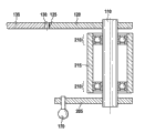
Fig. 2 illustrates the section drawing of a part of the Wiper system 100 of Fig. 1 with another kind of embodiment.Direction of observation provides with cross section A-A in Fig. 1.
The hand of rotation of the second wiper shaft 115 also extends in the same way with the first wiper shaft 110 in this embodiment.
Claims (8)
1. be used for being installed in the Wiper system (100) of self-propelled vehicle (105), comprise:
-for the wiper shaft (110) that swingingly drives Wiper arm,
-reversible drive motor (155),
-be used for to transmit the transfer device on the wiper shaft (110) of moving to of drive motor (155), it is characterized in that,
-described transfer device has the sector section (120) that is located on the wiper shaft (110), is engaged with the gear (160) or another sector section (135) that are located on the drive motor (155) in this sector section.
2. Wiper system as claimed in claim 1 (100) is characterized in that, is provided with another wiper shaft (115), is used for swingingly driving another Wiper arm, and wherein said wiper shaft (110,115) utilization is coupled transmission device (165) and interconnects.
3. Wiper system as claimed in claim 2 (100) is characterized in that, described wiper shaft (110) is located in the position of driver's side of self-propelled vehicle (105).
4. such as each described Wiper system (100) in the claim 2 to 3, it is characterized in that, arrange the driver element (170) that is coupled transmission device (165) at described gear (160) or another sector section (135).
5. such as each described Wiper system (100) in the above-mentioned claim, it is characterized in that described sector section (120) has gear (160) or the larger radius of action of another sector section (135) that is engaged in this sector section than described.
6. such as each described Wiper system (100) in the above-mentioned claim, it is characterized in that the tooth section (125) of described sector section (120) surrounds less than about 90 ° angle based on wiper shaft.
7. such as each described Wiper system (100) in the above-mentioned claim, it is characterized in that described drive motor (155) comprises retarder (145).
8. such as each described Wiper system (100) in the above-mentioned claim, it is characterized in that, be provided with retaining element (197), be used for supporting drive motor (155) and wiper shaft (110), wherein said drive motor (155) is transformable to the distance of wiper shaft (110).
Applications Claiming Priority (3)
| Application Number | Priority Date | Filing Date | Title |
|---|---|---|---|
| DE201010038595 DE102010038595A1 (en) | 2010-07-29 | 2010-07-29 | wiper device |
| DE102010038595.6 | 2010-07-29 | ||
| PCT/EP2011/058890 WO2012013395A1 (en) | 2010-07-29 | 2011-05-31 | Wiper device |
Publications (2)
| Publication Number | Publication Date |
|---|---|
| CN103003108A true CN103003108A (en) | 2013-03-27 |
| CN103003108B CN103003108B (en) | 2016-01-20 |
Family
ID=44483900
Family Applications (1)
| Application Number | Title | Priority Date | Filing Date |
|---|---|---|---|
| CN201180036966.5A Expired - Fee Related CN103003108B (en) | 2010-07-29 | 2011-05-31 | Wiper system |
Country Status (5)
| Country | Link |
|---|---|
| EP (1) | EP2598383B1 (en) |
| CN (1) | CN103003108B (en) |
| BR (1) | BR112013002001A2 (en) |
| DE (1) | DE102010038595A1 (en) |
| WO (1) | WO2012013395A1 (en) |
Families Citing this family (2)
| Publication number | Priority date | Publication date | Assignee | Title |
|---|---|---|---|---|
| CN103481861A (en) * | 2013-09-05 | 2014-01-01 | 唐山轨道客车有限责任公司 | Electric window wiper for locomotives and high-speed trains |
| US11555752B2 (en) | 2020-02-12 | 2023-01-17 | Honda Motor Co., Ltd. | Systems and methods of verifying the assembly of a vehicle wiper assembly |
Citations (4)
| Publication number | Priority date | Publication date | Assignee | Title |
|---|---|---|---|---|
| WO2002006096A1 (en) * | 2000-07-19 | 2002-01-24 | Robert Bosch Gmbh | Windscreen wiper system comprising a tubular bearing rod |
| DE10306390A1 (en) * | 2003-02-15 | 2004-08-26 | Volkswagen Ag | Windscreen wiper system for vehicle has driven shaft of drive unit guided through wall of vehicle's body, and gear is installed on outer side of body, and with wiper shaft supporting wiper arm installed in region in front of windscreen |
| CN2642602Y (en) * | 2003-08-01 | 2004-09-22 | 蒋辉敏 | Windshield wiper capable of swinging to the angle of 180degree |
| CN201410933Y (en) * | 2009-04-30 | 2010-02-24 | 浙江关西电机有限公司 | Automobile electric windshield wiper |
Family Cites Families (5)
| Publication number | Priority date | Publication date | Assignee | Title |
|---|---|---|---|---|
| GB851276A (en) * | 1958-05-01 | 1960-10-12 | Gen Motors Ltd | Improvements in or relating to windscreen wiper systems |
| DE3237269A1 (en) * | 1982-10-08 | 1984-04-12 | SWF-Spezialfabrik für Autozubehör Gustav Rau GmbH, 7120 Bietigheim-Bissingen | Drive device, in particular for windscreen wipers on motor vehicles |
| DE10261926A1 (en) * | 2002-12-23 | 2004-07-01 | Robert Bosch Gmbh | Drive arrangement of a wiper device for windows of motor vehicles |
| DE10359968A1 (en) * | 2003-12-18 | 2005-07-21 | Valeo Systèmes d`Essuyage | wiper system |
| DE102009014312A1 (en) * | 2009-03-25 | 2010-09-30 | Valeo Systèmes d'Essuyage | Electromotive auxiliary drive, in particular wiper drive |
-
2010
- 2010-07-29 DE DE201010038595 patent/DE102010038595A1/en not_active Withdrawn
-
2011
- 2011-05-31 CN CN201180036966.5A patent/CN103003108B/en not_active Expired - Fee Related
- 2011-05-31 EP EP11725376.5A patent/EP2598383B1/en not_active Not-in-force
- 2011-05-31 WO PCT/EP2011/058890 patent/WO2012013395A1/en active Application Filing
- 2011-05-31 BR BR112013002001A patent/BR112013002001A2/en not_active IP Right Cessation
Patent Citations (4)
| Publication number | Priority date | Publication date | Assignee | Title |
|---|---|---|---|---|
| WO2002006096A1 (en) * | 2000-07-19 | 2002-01-24 | Robert Bosch Gmbh | Windscreen wiper system comprising a tubular bearing rod |
| DE10306390A1 (en) * | 2003-02-15 | 2004-08-26 | Volkswagen Ag | Windscreen wiper system for vehicle has driven shaft of drive unit guided through wall of vehicle's body, and gear is installed on outer side of body, and with wiper shaft supporting wiper arm installed in region in front of windscreen |
| CN2642602Y (en) * | 2003-08-01 | 2004-09-22 | 蒋辉敏 | Windshield wiper capable of swinging to the angle of 180degree |
| CN201410933Y (en) * | 2009-04-30 | 2010-02-24 | 浙江关西电机有限公司 | Automobile electric windshield wiper |
Also Published As
| Publication number | Publication date |
|---|---|
| WO2012013395A1 (en) | 2012-02-02 |
| CN103003108B (en) | 2016-01-20 |
| DE102010038595A1 (en) | 2012-02-02 |
| BR112013002001A2 (en) | 2016-06-14 |
| EP2598383B1 (en) | 2016-01-20 |
| EP2598383A1 (en) | 2013-06-05 |
Similar Documents
| Publication | Publication Date | Title |
|---|---|---|
| US8424880B2 (en) | Camber angle changing mechanism | |
| CN204368366U (en) | A kind of children's drift car | |
| CN103081309A (en) | Wiper motor | |
| CN107985216B (en) | Vehicle-mounted display terminal assembly and vehicle | |
| CN101274620A (en) | Wiper apparatus for vehicle | |
| CN107139887B (en) | Automobile wiper | |
| EP2298621A3 (en) | Universal actuation and control of steering mechanisms for mobile vehicles | |
| US8234745B2 (en) | Motor device and wiper apparatus | |
| CN203719075U (en) | Automatic swing mechanism and air conditioner with same | |
| US7420346B2 (en) | Drive arrangement for a wiper device for windows of motor vehicles | |
| CN102427972B (en) | Windshield wiper device | |
| CN103003108B (en) | Wiper system | |
| CN109808481B (en) | Wheel mechanism based on hub motor, electric unmanned vehicle chassis and electric unmanned vehicle | |
| US11541760B2 (en) | Current collector assembly for a vehicle | |
| CN202294694U (en) | Motor component for vehicle rear windscreen wiper | |
| CN103081308B (en) | Wiper motor | |
| CN105793127A (en) | Wiper device | |
| CN211281446U (en) | Actuating mechanism of unmanned aerial vehicle elevator | |
| CN105656415A (en) | Sun linkage tracking device | |
| CN110182279A (en) | A kind of differential drive device | |
| CN103511940B (en) | Light fixture | |
| CN106167000B (en) | Wiper drive | |
| US20110192244A1 (en) | Drive device | |
| CN211287198U (en) | Electric driving mechanism for automobile door | |
| CN1288007C (en) | Driving bearing device of external lens support arm |
Legal Events
| Date | Code | Title | Description |
|---|---|---|---|
| C06 | Publication | ||
| PB01 | Publication | ||
| C10 | Entry into substantive examination | ||
| SE01 | Entry into force of request for substantive examination | ||
| C14 | Grant of patent or utility model | ||
| GR01 | Patent grant | ||
| CF01 | Termination of patent right due to non-payment of annual fee | ||
| CF01 | Termination of patent right due to non-payment of annual fee |
Granted publication date: 20160120 Termination date: 20180531 |