CN102926942B - Wind energy and solar energy integrated complementary rotating cylinder - Google Patents
Wind energy and solar energy integrated complementary rotating cylinder Download PDFInfo
- Publication number
- CN102926942B CN102926942B CN201210474469.XA CN201210474469A CN102926942B CN 102926942 B CN102926942 B CN 102926942B CN 201210474469 A CN201210474469 A CN 201210474469A CN 102926942 B CN102926942 B CN 102926942B
- Authority
- CN
- China
- Prior art keywords
- shaft
- rotating sleeve
- solar energy
- ring
- wind
- Prior art date
- Legal status (The legal status is an assumption and is not a legal conclusion. Google has not performed a legal analysis and makes no representation as to the accuracy of the status listed.)
- Expired - Fee Related
Links
Images


Classifications
-
- Y—GENERAL TAGGING OF NEW TECHNOLOGICAL DEVELOPMENTS; GENERAL TAGGING OF CROSS-SECTIONAL TECHNOLOGIES SPANNING OVER SEVERAL SECTIONS OF THE IPC; TECHNICAL SUBJECTS COVERED BY FORMER USPC CROSS-REFERENCE ART COLLECTIONS [XRACs] AND DIGESTS
- Y02—TECHNOLOGIES OR APPLICATIONS FOR MITIGATION OR ADAPTATION AGAINST CLIMATE CHANGE
- Y02B—CLIMATE CHANGE MITIGATION TECHNOLOGIES RELATED TO BUILDINGS, e.g. HOUSING, HOUSE APPLIANCES OR RELATED END-USER APPLICATIONS
- Y02B10/00—Integration of renewable energy sources in buildings
- Y02B10/10—Photovoltaic [PV]
-
- Y—GENERAL TAGGING OF NEW TECHNOLOGICAL DEVELOPMENTS; GENERAL TAGGING OF CROSS-SECTIONAL TECHNOLOGIES SPANNING OVER SEVERAL SECTIONS OF THE IPC; TECHNICAL SUBJECTS COVERED BY FORMER USPC CROSS-REFERENCE ART COLLECTIONS [XRACs] AND DIGESTS
- Y02—TECHNOLOGIES OR APPLICATIONS FOR MITIGATION OR ADAPTATION AGAINST CLIMATE CHANGE
- Y02B—CLIMATE CHANGE MITIGATION TECHNOLOGIES RELATED TO BUILDINGS, e.g. HOUSING, HOUSE APPLIANCES OR RELATED END-USER APPLICATIONS
- Y02B10/00—Integration of renewable energy sources in buildings
- Y02B10/30—Wind power
-
- Y—GENERAL TAGGING OF NEW TECHNOLOGICAL DEVELOPMENTS; GENERAL TAGGING OF CROSS-SECTIONAL TECHNOLOGIES SPANNING OVER SEVERAL SECTIONS OF THE IPC; TECHNICAL SUBJECTS COVERED BY FORMER USPC CROSS-REFERENCE ART COLLECTIONS [XRACs] AND DIGESTS
- Y02—TECHNOLOGIES OR APPLICATIONS FOR MITIGATION OR ADAPTATION AGAINST CLIMATE CHANGE
- Y02E—REDUCTION OF GREENHOUSE GAS [GHG] EMISSIONS, RELATED TO ENERGY GENERATION, TRANSMISSION OR DISTRIBUTION
- Y02E10/00—Energy generation through renewable energy sources
- Y02E10/50—Photovoltaic [PV] energy
-
- Y—GENERAL TAGGING OF NEW TECHNOLOGICAL DEVELOPMENTS; GENERAL TAGGING OF CROSS-SECTIONAL TECHNOLOGIES SPANNING OVER SEVERAL SECTIONS OF THE IPC; TECHNICAL SUBJECTS COVERED BY FORMER USPC CROSS-REFERENCE ART COLLECTIONS [XRACs] AND DIGESTS
- Y02—TECHNOLOGIES OR APPLICATIONS FOR MITIGATION OR ADAPTATION AGAINST CLIMATE CHANGE
- Y02E—REDUCTION OF GREENHOUSE GAS [GHG] EMISSIONS, RELATED TO ENERGY GENERATION, TRANSMISSION OR DISTRIBUTION
- Y02E10/00—Energy generation through renewable energy sources
- Y02E10/70—Wind energy
- Y02E10/74—Wind turbines with rotation axis perpendicular to the wind direction
-
- Y—GENERAL TAGGING OF NEW TECHNOLOGICAL DEVELOPMENTS; GENERAL TAGGING OF CROSS-SECTIONAL TECHNOLOGIES SPANNING OVER SEVERAL SECTIONS OF THE IPC; TECHNICAL SUBJECTS COVERED BY FORMER USPC CROSS-REFERENCE ART COLLECTIONS [XRACs] AND DIGESTS
- Y02—TECHNOLOGIES OR APPLICATIONS FOR MITIGATION OR ADAPTATION AGAINST CLIMATE CHANGE
- Y02E—REDUCTION OF GREENHOUSE GAS [GHG] EMISSIONS, RELATED TO ENERGY GENERATION, TRANSMISSION OR DISTRIBUTION
- Y02E70/00—Other energy conversion or management systems reducing GHG emissions
- Y02E70/30—Systems combining energy storage with energy generation of non-fossil origin
Landscapes
- Wind Motors (AREA)
Abstract
The invention discloses a wind energy and solar energy integrated complementary rotating cylinder comprising a vertical post principal shaft, a rotating sleeve, a horizontal supporting rod and an inclined supporting rod; the rotating sleeve is sleeved on an upper end shaft of the vertical post principal shaft; the rotating cylinder is characterized in that an upper cylinder body is fixed at the outer side of the rotating sleeve by the horizontal supporting rod and the inclined supporting rod; a plurality of wind cups arrayed at equal intervals are arranged at the upper edge of the cylinder body; a coil is fixedly sleeved at the lower part of the upper end shaft of the vertical post principal shaft in the rotating sleeve; a ring-shaped magnet is arranged on the inner wall of the rotating sleeve; a plurality of ring-shaped storage cells which are connected with each other by using leads and coils are fixed on the upper end of the vertical post principal shaft; and an umbrella-shaped solar photovoltaic cell panel is fixed on the top end of the upper end shaft of the vertical post principal shaft. Because the wind energy and solar energy integrated complementary rotating cylinder integrates wind energy and solar energy and uses the wind energy and the solar energy in a complementary form according to weather variations, the using ratio of the wind energy and the solar energy can be increased, and meanwhile, the structure is more reasonable and the rotating cylinder is safer to use. The rotating cylinder can be used for the advertisement field, power generation and illumination of building fields, and the like.
Description
Technical field
The present invention relates to the improvement of a kind of wind energy and helioplant, belong to natural energy resources and develop field, specifically a kind of by wind energy drive rotation, again by wind energy auto-control rotating speed and wind loading rating, and with collection wind energy and the complementary rotary drum of solar energy one of solar energy complementation.Can be used in the field such as ad production or generating, building yard illumination.
Background technique
Wind energy and solar energy are a kind of inexhaustible, nexhaustible green energy resources, and its application area is quite extensive, also have many reports in the application of advertisement field and power field.But in application, there are many insoluble problems, the longest problem of encountering: the one, wind-force is less than 3m/ second, is not enough to form effective wind speed, turn and do not rotate, or rotating speed is extremely slow, and in the time that wind-force exceedes 6 grades, the rotating speed of turning is too fast, destroys even the structure of turning and connecting; The 2nd, effective wind energy and effectively solar energy often can not have simultaneously, when solar energy is sufficient, invalid wind speed often, and in the weather of strong wind, overcast and rainy often again, so, no matter be turning of wind energy driving, or the turning of Driven by Solar Energy, single employing, is difficult to reach the effect of round-the-clock onset; The 3rd, the wind energy using is at present turned, be generally the stressed asymmetrical plate rotating around vertical pivot, wind loading rating is not strong, one meets high wind, and stressed plate will be damaged, and turns for the wind energy that power generating equipment is installed, also there is the shortcoming of center of gravity deflection, the deflection of this center of gravity, has strengthened wearing and tearing, has reduced wind loading rating.At present, at building yard, also do not adopt the report of wind energy and solar lighting, advertisement, the lighting set using at building yard remains and adopts civil power and incandescent lamp, important building yard sometimes construction period will reach several years, so the electricity consumption causing waste is also very intuitively.
Summary of the invention
The object of the present invention is to provide one to be devoted to solve above the deficiencies in the prior art, realize collection wind energy and the complementary rotary drum of solar energy one of using electricity wisely.
In order to reach above object, the technical solution adopted in the present invention is: this collection wind energy and the complementary rotary drum of solar energy one, comprise column main shaft, fixed base, rotating sleeve, horizontal support bar and inclined support bar, what column main shaft was vertical is fixed on fixed base, fixed base is fixed on the ground cement seat that needs to install by stone bolt again, rotating sleeve is sleeved on the upper shaft of column main shaft, it is characterized in that: the outside suit upper cylinder of described rotating sleeve, between the inwall of cylindrical shell and the outer wall of rotating sleeve, be fixedly connected with inclined support bar by horizontal support bar, and make the axis coinciding of cylindrical shell and rotating sleeve, on the upper edge of cylindrical shell, be provided with the vane of equidistant arrangement, the vane that the principle of vane is used with meteorological department is identical, the coil of cutting magnetic field on the upper shaft bottom fixed cover of the column main shaft in rotating sleeve, the producing principle of the coil of cutting magnetic field is with the rotor of generator, on the inwall of rotating sleeve, be provided with the ring magnet corresponding with the coil of cutting magnetic field, its producing principle is with the stator of generator, in the time that rotating sleeve rotates, ring magnet rotates with respect to the coil of cutting magnetic field, causes the coil cutting magnetic line of cutting magnetic field, generation current, ring-type storage battery on fixing on the upper shaft of the column main shaft on the coil top of cutting magnetic field, ring-type storage battery is connected with the coil of cutting magnetic field by wire, and the electric current producing stores by ring-type storage battery, upper shaft top at column main shaft is bolted umbrella-shaped solar energy photovoltaic battery panel, umbrella-shaped solar energy photovoltaic battery panel is connected with ring-type storage battery by wire, like this, can make that sun-generated electric power and wind energy power supply are complementary to be shared, overcome the deficiency that available wind energy has when different from solar energy.
The present invention also implements by following measure: described umbrella-shaped solar energy photovoltaic battery panel sunny slope is solar photovoltaic cell panel, and opaco is black liner plate, is jointly fixed on the outer wall of cone.
In the upper and lower port of described rotating sleeve, be equipped with bearing, the diapire of rotating sleeve is provided with horizontal annular bearings.
The back side and the rotating shaft of described vane are fixed, insert in volume box the lower end of rotating shaft, in rotating shaft at volume in box around on wind spring, at the fixing upper baffle ring in the bottom of rotating shaft, volume box is fixed on the upper edge inwall of cylindrical shell, in the time that wind-force is excessive, vane, because unbalance stress can rotate, makes the mouth wind direction dorsad of vane, in the time that wind-force reduces, under the effect of wind spring, recover again the mouth of vane towards the position of wind direction; The elastic force of wind spring is adjustable, and while being generally adjusted to strong breeze, vane can turn to; Described vane is provided with 3.
Described ring-type storage battery, be composed in series by 4 storage batteries, every storage battery account for column main shaft upper shaft girth 1/5, leave a breach micromachine be installed, the mainshaft gear of micromachine engages with the gear ring on rotating sleeve inwall, and insulating resin is filled by the surrounding of micromachine; A horizontal support bar is therein provided with skewed slot, in skewed slot, be provided with conducting sphere, the switch contact of micromachine is located at skewed slot inner bottom part, and skewed slot is that ecto-entad is oblique downwards, its gradient can require to limit according to wind-force, as change while being designed to wind-force 5m/ second,, in the time that wind-force exceedes 5m/ second, conducting sphere is under the effect of centrifugal force, along skewed slot to outer rolling, the switch contact that leaves bottom, skewed slot the inner, micromachine stops operating, and the rotation of cylindrical shell is only the driving of wind-force; In the time that wind-force is less than 5m/ second, conducting sphere, under the effect of self gravitation, inwardly rolls along skewed slot, the switch contact place that is rolled to bottom, skewed slot the inner, switches on power micromachine, and micromachine rotates, just drive rotating sleeve to rotate, also can make barrel body rotation thereby realized at calm or wind hour.
The bottom of described column main shaft is cone-shaped, by the principle design of wind energy conversion system main shaft.
Described umbrella-shaped solar energy photovoltaic battery panel is single crystal silicon or polycrystal silicon cell.
When as advertisement, be loaded with advertisement picture on the surface of cylindrical shell, and on cylindrical shell, be furnished with the LED lamp of combination, the current supply line of LED lamp is conducted by ring-type contact and ring-type storage battery, can be used as billboard.
Beneficial effect of the present invention is: compare with the utilized device of current wind energy and solar energy, due to by wind energy with solar energy is integrated and use according to weather variation is complementary, so can improve the utilization ratio of wind energy and solar energy, simultaneously, structure is more reasonable, use safelyr, can not only be applicable to advertisement field, also can be used for the fields such as generating, building yard illumination.
Accompanying drawing explanation
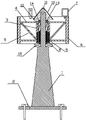
Fig. 1 is structure front-view schematic diagram of the present invention;
Fig. 2 is structure of the present invention cross-sectional schematic vertically;
Fig. 3 is that enlarged diagram is analysed and observe in umbrella-shaped solar energy photovoltaic battery panel of the present invention transverse section;
Fig. 4 of the present inventionly axially analyses and observe enlarged diagram along vane;
Fig. 5 is that enlarged diagram is overlooked in the assembling along ring-type storage battery of the present invention;
Fig. 6 is that the assembly structure of conducting sphere of the present invention and switch contact, horizontal support bar is analysed and observe enlarged diagram.
In figure: 1, column main shaft; 2, fixed base; 3, rotating sleeve; 4, horizontal support bar; 5, inclined support bar; 6, cylindrical shell; 7, vane; 7a, rotating shaft; 7b, volume box; 7c, wind spring; 7d, baffle ring; 8, coil; 9, ring magnet; 10, ring-type storage battery; 10a, storage battery; 10b, resin; 10c, mainshaft gear; 10d, micromachine; 11, bolt; 12, umbrella-shaped solar energy photovoltaic battery panel; 12a, solar photovoltaic cell panel; 12b, black liner plate; 12c, cone; 13, ring-type contact; 14, bearing; 15, horizontal annular bearings; 16, gear ring; 17, conducting sphere; 18, switch contact; 19, skewed slot.
Embodiment
Embodiment 1
Fig. 1, Fig. 2, Fig. 3, Fig. 4, Fig. 5, Fig. 6 have provided the embodiment of the board of preparing advertising.This collection wind energy and the complementary rotary drum of solar energy one, comprise column main shaft 1, fixed base 2, rotating sleeve 3, horizontal support bar 4 and inclined support bar 5, what column main shaft 1 was vertical is fixed on fixed base 2, fixed base 2 is fixed on the ground cement seat that needs to install by stone bolt again, rotating sleeve 3 is sleeved on the upper shaft of column main shaft 1, it is characterized in that: the outside suit upper cylinder 6 of described rotating sleeve 3, between the outer wall of the inwall of cylindrical shell 6 and rotating sleeve 3, be fixedly connected with inclined support bar 5 by horizontal support bar 4, and make the axis coinciding of cylindrical shell 6 and rotating sleeve 3, on the upper edge of cylindrical shell 6, be provided with the vane 7 of equidistant arrangement, the vane that the principle of vane 7 is used with meteorological department is identical, in the situation that having wind, by the suffered blast difference of the different side surfaces of vane 7, and drive cylindrical shell 6 to rotate, the coil 8 of cutting magnetic field on the upper shaft bottom fixed cover of the column main shaft 1 in rotating sleeve 3, the producing principle of the coil 8 of cutting magnetic field is with the rotor of generator, on the inwall of rotating sleeve 3, be provided with the ring magnet corresponding with the coil 8 of cutting magnetic field 9, its producing principle is with the stator of generator, in the time that rotating sleeve 3 rotates, ring magnet 9 rotates with respect to the coil 8 of cutting magnetic field, causes coil 8 cutting magnetic lines of cutting magnetic field, generation current, ring-type storage battery 10 on fixing on the upper shaft of the column main shaft 1 on coil 8 tops of cutting magnetic field, ring-type storage battery 10 is connected with the coil 8 of cutting magnetic field by wire, and the electric current producing stores by ring-type storage battery 10, umbrella-shaped solar energy photovoltaic battery panel 12 is fixed by bolt 11 in upper shaft top at column main shaft 1, umbrella-shaped solar energy photovoltaic battery panel 12 is connected with ring-type storage battery 10 by wire, like this, can make sun-generated electric power and wind energy power supply share according to weather rule is complementary, overcome the deficiency that available wind energy has when different from solar energy.
As improvement of the present invention: described umbrella-shaped solar energy photovoltaic battery panel 12 sunny slopes are solar photovoltaic cell panel 12a, and opaco is black liner plate 12b, to play a beauty function, be jointly fixed on the outer wall of cone 12c;
In the upper and lower port of described rotating sleeve 3, be equipped with bearing 14, the diapire of rotating sleeve 3 is provided with horizontal annular bearings 15, to play holder role;
The back side and the rotating shaft 7a of described vane 7 fix, insert in volume box 7b the lower end of rotating shaft 7a, on rotating shaft 7a in volume box 7b around on wind spring 7c, at the fixing upper baffle ring 7d in the bottom of rotating shaft 7a, volume box 7b is fixed on the upper edge inwall of cylindrical shell 6, in the time that wind-force is excessive, vane 7, because unbalance stress can rotate, makes the mouth wind direction dorsad of vane 7, in the time that wind-force reduces, under the effect of wind spring 7c, recover again the mouth of vane 7 towards the position of wind direction; The elastic force of wind spring 7c is adjustable, and while being generally adjusted to strong breeze, vane 7 can turn to; Described vane 7 is provided with 3;
Described ring-type storage battery 10, be composed in series by 4 storage battery 10a, every storage battery 10a account for column main shaft 1 upper shaft girth 1/5, leave a breach micromachine 10d is installed, the mainshaft gear 10c of micromachine 10d engages with the gear ring 16 on rotating sleeve 3 inwalls, and insulating resin 10b fills in the surrounding of micromachine 10d; A horizontal support bar 4 is therein provided with skewed slot 19, in skewed slot 19, be provided with conducting sphere 17, the switch contact 18 of micromachine 10d is located at skewed slot 19 inner bottom parts, skewed slot 19 is that ecto-entad is oblique downwards, its gradient can require to limit according to wind-force, while being designed to wind-force 5m/ second, change, in the time that wind-force exceedes 5m/ second, conducting sphere 17 is under the effect of centrifugal force, along skewed slot 19 to outer rolling, the switch contact 18 that leaves skewed slot 19 inner bottoms, micromachine 10d stops operating, and the rotation of cylindrical shell 6 is only the driving of wind-force; In the time that wind-force is less than 5m/ second, conducting sphere 17 is under the effect of self gravitation, inwardly roll along skewed slot 19, switch contact 18 places that are rolled to skewed slot 19 inner bottoms, switch on power micromachine 10d, and micromachine 10d rotates, just drive rotating sleeve 3 to rotate, thereby realize at calm or wind hour, by discharging the electric weight of ring-type storage battery 10, driven cylindrical shell 6 to rotate by micromachine 10d;
The bottom of described column main shaft 1 is cone-shaped, by the principle design of wind energy conversion system main shaft;
Described umbrella-shaped solar energy photovoltaic battery panel 12 is single crystal silicon or polycrystal silicon cell;
The surface of described cylindrical shell 6 is loaded with advertisement picture, and on cylindrical shell 6, is furnished with the LED lamp of combination, and the current supply line of LED lamp is conducted by ring-type contact 13 and ring-type storage battery 10, can carry out advertisement.
Claims (2)
1. collection wind energy and the complementary rotary drum of solar energy one, comprise column main shaft (1), fixed base (2), rotating sleeve (3), horizontal support bar (4) and inclined support bar (5), what column main shaft (1) was vertical is fixed on fixed base (2), rotating sleeve (3) is sleeved on the upper shaft of column main shaft (1), it is characterized in that: the outside suit upper cylinder (6) of described rotating sleeve (3), between the outer wall of the inwall of cylindrical shell (6) and rotating sleeve (3), be fixedly connected with inclined support bar (5) by horizontal support bar (4), and make the axis coinciding of cylindrical shell (6) and rotating sleeve (3), above be provided with the vane (7) of equidistant arrangement on the upper edge of cylindrical shell (6), the coil (8) of cutting magnetic field on the upper shaft bottom fixed cover of the column main shaft (1) in rotating sleeve (3) is provided with the ring magnet (9) corresponding with the coil (8) of cutting magnetic field on the inwall of rotating sleeve (3), fixing upper ring-type storage battery (10) on the upper shaft of the column main shaft (1) on coil (8) top of cutting magnetic field, ring-type storage battery (10) is connected with the coil (8) of cutting magnetic field by wire, upper umbrella-shaped solar energy photovoltaic battery panel (12) is fixed by bolt (11) in upper shaft top at column main shaft (1), and umbrella-shaped solar energy photovoltaic battery panel (12) is connected with ring-type storage battery (10) by wire, the back side of described vane (7) and rotating shaft (7a) are fixing, insert in volume box (7b) lower end of rotating shaft (7a), rotating shaft (7a) in volume box (7b) is upper around upper wind spring (7c), at the fixing upper baffle ring (7d) in the bottom of rotating shaft (7a), volume box (7b) is fixed on the upper edge inwall of cylindrical shell (6), described ring-type storage battery (10), be composed in series by 4 storage batteries (10a), every storage battery (10a) account for column main shaft (1) upper shaft girth 1/5, leave a breach micromachine (10d) is installed, the mainshaft gear (10c) of micromachine (10d) engages with the gear ring (16) on rotating sleeve (3) inwall, and insulating resin (10b) is filled by the surrounding of micromachine (10d), a horizontal support bar (4) is therein provided with skewed slot (19), is provided with conducting sphere (17) in skewed slot (19), and the switch contact (18) of micromachine (10d) is located at skewed slot (19) inner bottom part, and skewed slot (19) is that ecto-entad is oblique downwards.
2. collection wind energy according to claim 1 and the complementary rotary drum of solar energy one, it is characterized in that: described umbrella-shaped solar energy photovoltaic battery panel (12) sunny slope is solar photovoltaic cell panel (12a), opaco is black liner plate (12b), is jointly fixed on the outer wall of cone (12c).
Priority Applications (1)
| Application Number | Priority Date | Filing Date | Title |
|---|---|---|---|
| CN201210474469.XA CN102926942B (en) | 2012-11-21 | 2012-11-21 | Wind energy and solar energy integrated complementary rotating cylinder |
Applications Claiming Priority (1)
| Application Number | Priority Date | Filing Date | Title |
|---|---|---|---|
| CN201210474469.XA CN102926942B (en) | 2012-11-21 | 2012-11-21 | Wind energy and solar energy integrated complementary rotating cylinder |
Publications (2)
| Publication Number | Publication Date |
|---|---|
| CN102926942A CN102926942A (en) | 2013-02-13 |
| CN102926942B true CN102926942B (en) | 2014-07-09 |
Family
ID=47641839
Family Applications (1)
| Application Number | Title | Priority Date | Filing Date |
|---|---|---|---|
| CN201210474469.XA Expired - Fee Related CN102926942B (en) | 2012-11-21 | 2012-11-21 | Wind energy and solar energy integrated complementary rotating cylinder |
Country Status (1)
| Country | Link |
|---|---|
| CN (1) | CN102926942B (en) |
Families Citing this family (1)
| Publication number | Priority date | Publication date | Assignee | Title |
|---|---|---|---|---|
| CN105679184A (en) * | 2015-06-24 | 2016-06-15 | 合肥德广广告传媒有限公司 | Wind-power advertising device for information display of animal husbandry |
Citations (5)
| Publication number | Priority date | Publication date | Assignee | Title |
|---|---|---|---|---|
| CN101403481A (en) * | 2008-09-28 | 2009-04-08 | 杨晓莹 | Wind-light complementation magnetic suspension slight breeze power generation road lamp |
| CN201241798Y (en) * | 2008-08-04 | 2009-05-20 | 赵幼仪 | High efficient wind power electric generator |
| CN102477966A (en) * | 2010-11-23 | 2012-05-30 | 大连创达技术交易市场有限公司 | Device for generating electricity under complementary action of low-wind-speed wind energy and solar energy |
| CN202417835U (en) * | 2012-01-13 | 2012-09-05 | 李国坤 | Vertical axis wind turbine integrated with solar power generation components |
| CN202900546U (en) * | 2012-11-21 | 2013-04-24 | 山东正顺建设集团有限公司 | Complementary rotating cylinder integrated with wind energy and solar energy |
-
2012
- 2012-11-21 CN CN201210474469.XA patent/CN102926942B/en not_active Expired - Fee Related
Patent Citations (5)
| Publication number | Priority date | Publication date | Assignee | Title |
|---|---|---|---|---|
| CN201241798Y (en) * | 2008-08-04 | 2009-05-20 | 赵幼仪 | High efficient wind power electric generator |
| CN101403481A (en) * | 2008-09-28 | 2009-04-08 | 杨晓莹 | Wind-light complementation magnetic suspension slight breeze power generation road lamp |
| CN102477966A (en) * | 2010-11-23 | 2012-05-30 | 大连创达技术交易市场有限公司 | Device for generating electricity under complementary action of low-wind-speed wind energy and solar energy |
| CN202417835U (en) * | 2012-01-13 | 2012-09-05 | 李国坤 | Vertical axis wind turbine integrated with solar power generation components |
| CN202900546U (en) * | 2012-11-21 | 2013-04-24 | 山东正顺建设集团有限公司 | Complementary rotating cylinder integrated with wind energy and solar energy |
Also Published As
| Publication number | Publication date |
|---|---|
| CN102926942A (en) | 2013-02-13 |
Similar Documents
| Publication | Publication Date | Title |
|---|---|---|
| KR20120051893A (en) | Power generator of hybrid type | |
| CN202900546U (en) | Complementary rotating cylinder integrated with wind energy and solar energy | |
| CN102364094A (en) | Bidirectional wind barrel type magnetic suspension wind power generation device | |
| CN201155429Y (en) | Low resistance vertical shaft wind power plant | |
| CN110685862B (en) | Mountain wall-hanging type wind energy and rainwater power generation device | |
| CN205792363U (en) | A kind of wind energy and solar energy complementary power generation system | |
| CN202326021U (en) | Two-way air duct type magnetic suspension wind power generation device | |
| CN102926942B (en) | Wind energy and solar energy integrated complementary rotating cylinder | |
| KR20110112106A (en) | Vertical axis wind generator | |
| CN201517471U (en) | Small-power wind-driven generator with double groups of fan blades | |
| CN210195928U (en) | Photovoltaic and wind power coupling power generation device | |
| CN208027674U (en) | One kind having mixing regenerative resource LED display | |
| CN205025793U (en) | Exhaust fan that can complementaryly generate electricity | |
| JP2011047391A (en) | Suspension type rotary shaft support for vertical type wind turbine generator | |
| CN106884763A (en) | Three-dimensional environmental protection and energy saving wind generator tower | |
| CN209145774U (en) | A kind of wind power generation plant | |
| CN201705557U (en) | Vertical coaxial combined-type wind-driven generator | |
| CN203146226U (en) | Small-sized DC (direct current) wind power generation device | |
| CN203146222U (en) | Vertical shaft lever bucket-type stacked wind energy power producer | |
| CN108105040B (en) | It is a kind of to facilitate installation and the wind power generation plant with protective device | |
| CN206135767U (en) | Power generation facility is united with solar energy to domestic active following wind -force | |
| CN202954927U (en) | Multi-direction wind power generation device | |
| CN212726910U (en) | Small-size environmental protection power generation facility | |
| CN203925881U (en) | High efficiency vertical shaft stator and rotor row star-wheel contrary synchronous rotary wind-driven generator | |
| CN102192095A (en) | Vertical coaxial combined type wind driven generator |
Legal Events
| Date | Code | Title | Description |
|---|---|---|---|
| C06 | Publication | ||
| PB01 | Publication | ||
| C10 | Entry into substantive examination | ||
| SE01 | Entry into force of request for substantive examination | ||
| C14 | Grant of patent or utility model | ||
| GR01 | Patent grant | ||
| CF01 | Termination of patent right due to non-payment of annual fee |
Granted publication date: 20140709 Termination date: 20151121 |
|
| EXPY | Termination of patent right or utility model |