CN102854613A - Zoom lens and imaging apparatus - Google Patents
Zoom lens and imaging apparatus Download PDFInfo
- Publication number
- CN102854613A CN102854613A CN2012102158171A CN201210215817A CN102854613A CN 102854613 A CN102854613 A CN 102854613A CN 2012102158171 A CN2012102158171 A CN 2012102158171A CN 201210215817 A CN201210215817 A CN 201210215817A CN 102854613 A CN102854613 A CN 102854613A
- Authority
- CN
- China
- Prior art keywords
- lens
- zoom
- negative
- positive
- object side
- Prior art date
- Legal status (The legal status is an assumption and is not a legal conclusion. Google has not performed a legal analysis and makes no representation as to the accuracy of the status listed.)
- Pending
Links
Images


Classifications
-
- G—PHYSICS
- G02—OPTICS
- G02B—OPTICAL ELEMENTS, SYSTEMS OR APPARATUS
- G02B15/00—Optical objectives with means for varying the magnification
- G02B15/14—Optical objectives with means for varying the magnification by axial movement of one or more lenses or groups of lenses relative to the image plane for continuously varying the equivalent focal length of the objective
- G02B15/143—Optical objectives with means for varying the magnification by axial movement of one or more lenses or groups of lenses relative to the image plane for continuously varying the equivalent focal length of the objective having three groups only
- G02B15/1431—Optical objectives with means for varying the magnification by axial movement of one or more lenses or groups of lenses relative to the image plane for continuously varying the equivalent focal length of the objective having three groups only the first group being positive
- G02B15/143105—Optical objectives with means for varying the magnification by axial movement of one or more lenses or groups of lenses relative to the image plane for continuously varying the equivalent focal length of the objective having three groups only the first group being positive arranged +-+
Abstract
A zoom lens comprising, in order from the object side: a first lens group that has a positive refractive power; a second lens group that has a negative refractive power; and a third lens group that has a positive refractive power. Zooming is performed by changing spaces between the first to third lens groups during zooming from a wide-angle end to a telephoto end. The third lens group includes, in order from the object side, a positive lens group, having a positive refractive power, and a negative lens group, disposed to be close to the image side thereof and having a negative refractive power, with an air gap, which is widest in the third lens group, interposed therebetween. The following Conditional Expression (1) is satisfied. -0.45<fGF/fGR<-0.10, (1) where fGF is a focal length of the positive lens group, and fGR is a focal length of the negative lens group.
Description
Technical field
Present technique relates to zoom lens and imaging device.Specifically, present technique relates to the zoom lens that are suitable as for the optical imaging system of the lens device for interchanging of so-called Interchangeable lens digital camera, and the imaging device that uses it.
Background technology
Recently, use the imaging device as the Interchangeable lens digital camera of solid imaging element to be used widely.Such Interchangeable lens digital camera must have outstanding imaging performance, compactedness (compactness), low-cost and high zoom ratios.Especially, entry level telephoto zoom lens must have zoom ratio greater than five times (five magnification) and on the end focal length of dolly-out,ing dolly-back at about 450 millimeters nominal values under the 35 mm film equivalents (equivalent) half angle of view less than 3 ° focal range.
There are various known lens in zoom lens as being used for the Interchangeable lens digital camera.Especially, the lens as being fit to the telephoto zoom lens exist each by four lens combination or three known lens that lens combination consists of.For example, propose each and comprised successively the have positive refracting power first lens group of (refractive power), the lens (reference that has the second lens combination of negative refraction power and have the 3rd lens combination of positive refracting power from object side (object side), for example, JP-A-2004-029765 and JP-A-2008-122775).
Summary of the invention
Usually, in positive leading type optical system, especially, being used for most of cost priority entry level lens of Interchangeable lens digital camera etc., in optical system, usually have maximum gauge and heavy weight first lens group and be used for focusing on.Main cause is, is the constant irrelevant with zoom position because object distance changes the movable length of the first lens group that is used for focusing that causes, so mechanical arrangements is easy, and this configuration is highly beneficial with regard to cost.On the contrary, can consider the second lens combination is used for focusing on.But, be substituted in the constant advantage of total length of lens during the focusing, the difficulty of mechanical arrangements is increased, therefore, with regard to the ratio of performance to price, this focus method is more unfavorable than the focusing of first lens group.
First group focus on and second group focus in any case, focus lens group is arranged in the optical system place approaching with object side.Therefore, when planning or when laying focus lens group, must avoid the interference to the lens component that approaches with picture side (image side).For this reason, be difficult to just in time arrange the such member of image focu driving mechanism around focus lens group ground.So, must be arranged in the periphery of the 3rd lens combination back focusing on driving mechanism, the 3rd lens combination has the diameter of less, and is positioned on the position than the more approaching picture side in the position of the interference that can avoid different component.From this view point, in above-mentioned existing zoom lens, layout is relatively large for the diameter of the 3rd lens combination that focuses on the actuator that drives, so these lens are unfavorable for dwindling its overall dimensions.
Therefore, the size of the reduced whole lens of expectation by reducing the 3rd lens combination.
An embodiment of present technique is for zoom lens and the imaging device that comprises described zoom lens.Described zoom lens comprise successively from object side: the first lens group with positive refracting power; The second lens combination with negative refraction power; And the 3rd lens combination with positive refracting power.In described zoom lens, during the zoom from wide-angle side to the end of dolly-out,ing dolly-back, carry out zoom by the space that changes the first to the 3rd lens combination.Described the 3rd lens combination comprises the positive lens groups with positive refracting power and is arranged near it as side and have the negative lens group of negative refraction power that from object side intervenient is the widest air gap in the 3rd lens combination successively.Described zoom lens satisfy following conditional expression (1).
(1)-0.45<fGF/fGR<-0.10
Here, fGF is the focal length of described positive lens groups, and fGR is the focal length of described negative lens group.Thus, define the described positive lens groups GF of described the 3rd lens combination of formation and the focal distance ratio of described negative lens group GR.
And, in this embodiment of present technique, can further satisfy following conditional expression (2).
(2)0.1<L3/ft<0.2
Here, L3 is the length of described the 3rd lens combination on optical axis, and ft is the focal length of whole system on the end of dolly-out,ing dolly-back of described zoom lens.Thus, define the total length of described the 3rd lens combination.
In addition, in this embodiment of present technique, the described negative lens group that consists of described the 3rd lens combination can comprise be arranged to the most approaching with object side, have negative refraction power and by the positive lens that protrudes towards object side and the balsaming lens that forms towards the recessed negative lens of picture side.Can satisfy following conditional expression (3) and (4).
(3)0.2<(RLR1-RLR2)/(RLR1+RLR2)<0.8
(4)ndLR2>1.72
Here, RLR1 is the radius-of-curvature on described balsaming lens and the immediate surface of object side, and RLR2 is the radius-of-curvature on described balsaming lens and the immediate surface of picture side, and ndLR2 is the refractive index of negative lens on the d line.Thereby, define the ratio of the radius-of-curvature on described balsaming lens BL and the immediate surface of object side and itself and the radius-of-curvature on the immediate surface of picture side, and define the refractive index of the negative lens LR2 that consists of described balsaming lens BL.
In addition, in this embodiment of present technique, can further satisfy following conditional expression (5).
(5)vdp/vdn>1.18
Here, vdp is the Abbe number (Abbenumber) of positive lens on the d line that consists of described balsaming lens, and vdn is the Abbe number of negative lens on the d line that consists of described balsaming lens.Thus, define the relation of the Abbe number of the positive lens LR1 that consists of described balsaming lens BL and negative lens LR2.
In addition, in this embodiment of present technique, the described negative lens group that consists of described the 3rd lens combination comprises having negative refraction power and by the positive lens that protrudes towards object side and the balsaming lens and the second positive lens that form towards the recessed negative lens of picture side successively from object side.Thus, spherical aberration and the astigmatism on the wide-angle side and distortion during the zoom have been proofreaied and correct satisfactorily.
According to the embodiment of present technique, by reducing the diameter of the 3rd lens combination in the zoom lens, can obtain to dwindle whole lens size go out chromatic effect.
Accompanying drawing is full and clear
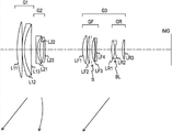
Fig. 1 is that illustration is according to the figure of the lens configuration of the zoom lens of present technique the first embodiment;
Fig. 2 A-2C is that illustration is according to the figure of the aberration (aberration) on the wide-angle side (wide angleend) of the zoom lens of present technique the first embodiment;
Fig. 3 A-3C is illustration according to the figure of the aberration on the wide-angle side of the zoom lens of present technique the first embodiment and the middle focal length between the end of dolly-out,ing dolly-back;
Fig. 4 A-4C is that illustration is according to the figure of the aberration on the end of dolly-out,ing dolly-back of the zoom lens of present technique the first embodiment;
Fig. 5 is that illustration is according to the figure of the lens configuration of the zoom lens of present technique the second embodiment;
Fig. 6 A-6C is that illustration is according to the figure of the aberration on the wide-angle side of the zoom lens of present technique the second embodiment;
Fig. 7 A-7C is illustration according to the figure of the aberration on the wide-angle side of the zoom lens of present technique the second embodiment and the middle focal length between the end of dolly-out,ing dolly-back;
Fig. 8 A-8C is that illustration is according to the figure of the aberration on the end of dolly-out,ing dolly-back of the zoom lens of present technique the second embodiment;
Fig. 9 is that illustration is according to the figure of the lens configuration of the zoom lens of present technique the 3rd embodiment;
Figure 10 A-10C is that illustration is according to the figure of the aberration on the wide-angle side of the zoom lens of present technique the 3rd embodiment;
Figure 11 A-11C is illustration according to the figure of the aberration on the wide-angle side of the zoom lens of present technique the 3rd embodiment and the middle focal length between the end of dolly-out,ing dolly-back;
Figure 12 A-12C is that illustration is according to the figure of the aberration on the end of dolly-out,ing dolly-back of the zoom lens of present technique the 3rd embodiment;
Figure 13 is that illustration is according to the figure of the lens configuration of the zoom lens of present technique the 4th embodiment;
Figure 14 A-14C is that illustration is according to the figure of the aberration on the wide-angle side of the zoom lens of present technique the 4th embodiment;
Figure 15 A-15C is illustration according to the figure of the aberration on the wide-angle side of the zoom lens of present technique the 4th embodiment and the middle focal length between the end of dolly-out,ing dolly-back;
Figure 16 A-16C is that illustration is according to the figure of the aberration on the end of dolly-out,ing dolly-back of the zoom lens of present technique the 4th embodiment; And
Figure 17 is illustration according to the zoom lens applications of present technique the first to the 4th embodiment in the figure of the example of imaging device.
Embodiment
Zoom lens according to present technique comprise the first lens group G1 with positive refracting power successively from object side; The second lens combination G2 with negative refraction power; And the 3rd lens combination G3 with positive refracting power.During the zoom from wide-angle side to the end of dolly-out,ing dolly-back, carry out zoom by the space that changes between the first to the 3rd lens combination G1-G3.The 3rd lens combination G3 comprises the positive lens groups GF with positive refracting power and is arranged near it as side and negative lens group GR with negative refraction power that from object side intervenient is air gap (air gap) the widest in the 3rd lens combination G3 successively.In the zoom lens according to present technique, by suitable formation the 3rd lens combination G3, make the size reduction of overall lens system.
In addition, preferably, make the zoom lens according to present technique satisfy following conditional expression (1).
-0.45<fGF/fGR<-0.10...(1)
Here, fGF is the focal length of positive lens groups GF, and fGR is the focal length of negative lens group GR.
Conditional expression (1) defines the positive lens groups GF that consists of the 3rd lens combination G3 and is arranged to the focal distance ratio of the negative lens group GR near with looking like side joint.If the end value of conditional expression (1) is less than its lower limit, then the refracting power of negative lens group GR is too strong comparatively speaking.Therefore, not only become and be difficult to the various aberrations of correction as spherical aberration (spherical aberration) and coma (coma aberration), and the relative sensitivity of the excentricity in the 3rd lens combination G3 is increased, and manufacture difficulty is increased, therefore this situation is not preferred.And, if the end value of conditional expression (1) is greater than its upper limit, a little less than then the refracting power of negative lens group GR becomes relatively, and a little less than the effect of positive lens groups GF converging and diverging ray becomes too.Therefore, the diameter that consists of lens diameter lens of minimum negative lens group GR in zoom-lens system is increased.
In addition, preferably, make the zoom lens according to present technique satisfy following conditional expression (2).
0.1<L3/ft<0.2...(2)
Here, L3 is the length of the 3rd lens combination G3 on optical axis, and ft is the focal length of whole system on the end of dolly-out,ing dolly-back of zoom lens.Conditional expression (2) defines the total length of the 3rd lens combination G3.If the end value of conditional expression (2) is less than its lower limit, then the total length of the 3rd lens combination G3 has shortened, and this situation is conducive to reduce the size of lens combination.But, in this case, must make the positive lens groups GF of formation the 3rd lens combination G3 and the separately refracting power grow of negative lens group GR.Therefore, be difficult to spherical aberration corrector etc., and the relative sensitivity of the excentricity in the 3rd lens combination G3 is increased.If the end value of conditional expression (2) is greater than its upper limit, then the total length of the 3rd lens combination G3 has increased, and the total length of lens combination is increased.Therefore be difficult to dwindle its size.
In addition, preferably, make zoom lens according to present technique satisfy following conditional expression (1 ') and (2 ') within the scope of conditional expression (1) and (2).
-035<fGF/fGR<-020...(1')
0.13<L3/ft<0.17...(2')
In addition, in the zoom lens according to present technique, preferably, the negative lens group GR that consists of the 3rd lens combination G3 comprise be arranged to the most approaching with object side, have negative refraction power and by the positive lens LR1 that protrudes towards object side and gummed (cemented) the lens BL that forms towards the recessed negative lens LR2 of picture side.Therefore, in order to make negative lens group GR will consist of the ray divergence of the positive lens groups GF convergence of the 3rd lens combination G3, the immediate surface of negative lens group GR and object side is protruded, thereby can suppress to be incident on the angle of lip-deep ray, and the spherical aberration of appearance is minimized.In addition, make balsaming lens BL and be recessed as the immediate surface of side, thereby make the outer ray height deflection of axle.Therefore, the lens diameter of balsaming lens BL is minimized.
In addition, preferably, make the zoom lens according to present technique satisfy following conditional expression (3) and (4).
0.2<(RLR1-RLR2)/(RLR1+RLR2)<0.8...(3)
ndLR2>1.72...(4)
Here, RLR1 is the radius-of-curvature on balsaming lens BL and the immediate surface of object side, and RLR2 is the radius-of-curvature on balsaming lens BL and the immediate surface of picture side, and ndLR2 is the refractive index of negative lens LR2 on the d line.
Conditional expression (3) defines the ratio of the radius-of-curvature on balsaming lens BL and the immediate surface of object side and itself and the radius-of-curvature on the immediate surface of picture side.If the end value of conditional expression (3) less than its lower limit, then is difficult to fully improve the negative refraction power of balsaming lens BL.Therefore, the diameter of negative lens group GR is increased, therefore this increase is unfavorable for reducing the size of whole lens combination.In addition, if the end value of conditional expression (3) greater than its upper limit, then balsaming lens BL is too strong to the effect of diverging ray with picture side immediate surface.Therefore, the sensitivity of the excentricity in the 3rd lens combination G3 is increased.This increase is unfavorable for making, and is difficult to guarantee back focal length.
On the other hand, conditional expression (4) defines the refractive index of the negative lens LR2 that consists of balsaming lens BL.If the end value of conditional expression (4) less than its lower limit, then in order to obtain necessary negative refraction power, excessively reduces the curvature as side surface of negative lens LR2.Therefore, spherical aberration, coma and the astigmatism (astigmatism) of appearance are excessively increased.As a result of, be difficult to proofread and correct aberration in the whole lens combination.
Note, preferably, make zoom lens according to present technique satisfy following conditional expression (3 ') and (4 ') within the scope of conditional expression (3) and (4).
0.3<(RLR1-RLR2)/(RLR1+RLR2)<0.7...(3')
ndLR2>1.80...(4')
In addition, preferably, make the zoom lens according to present technique further satisfy following conditional expression (5).
vdp/vdn>1.18...(5)
Here, vdp is the Abbe number (Abbenumber) of positive lens LR1 on the d line that consists of balsaming lens BL, and vdn is the Abbe number of negative lens LR2 on the d line that consists of balsaming lens BL.
Conditional expression (5) defines the relation of the Abbe number of the positive lens LR1 that consists of balsaming lens BL and negative lens LR2.If the end value of conditional expression (5) less than its lower limit, then is difficult to proofread and correct satisfactorily the aberration that appears among whole the 3rd lens combination G3.So, by the expression formula that satisfies condition (5), can be further correcting chromatic aberration satisfactorily, especially on the end of dolly-out,ing dolly-back.
In addition, preferably, make zoom lens according to present technique satisfy following conditional expression (5 ') within the scope of conditional expression (5).
vdp/vdn>1.23...(5')
In addition, in the zoom lens according to present technique, preferably, the negative lens group GR that consists of the 3rd lens combination G3 comprises having negative refraction power and by the positive lens LR1 that protrudes towards object side and the balsaming lens and the second positive lens LR3 that form towards the recessed negative lens LR2 of picture side successively from object side.The negative lens group GR that consists of the 3rd lens combination G3 has and proofreaies and correct the abaxial astigmatism that appears among first lens group G1 and the second lens combination G2 and the function of distortion.Therefore, in the configuration of negative lens group GR, be arranged to the picture side joint of the balsaming lens BL with negative refraction power the second positive lens LR3 near.Thus, can proofread and correct satisfactorily astigmatism on the wide-angle side and the spherical aberration during distortion and the zoom, and can easily guarantee back focal length.
In addition, in the zoom lens according to present technique, along with optical axis almost vertical direction move first lens group G1 in the middle of the final lens group G3 a lens combination or the part of a lens combination, thereby can moving images.As described above, comprise by along with the drive system of the optical axis detection system that almost vertical direction mobile lens group or its a part of detected image are fuzzy, mobile separately lens combination with movable length is applied to the combination of the control system of drive system according to the output of detection system according to the zoom lens of present technique.Therefore, the zoom lens according to present technique can play shockproof optical system.Especially, the balsaming lens BL of negative lens group GR by will consisting of the 3rd lens combination G3 is used for above-mentioned application, can alleviate the mis-behave that the variation that especially causes the aberration of problem when image moves causes, and the impact that the lens sizes that the setting of driving mechanism is caused increases minimizes.
Hereinafter, will the embodiment (hereinafter referred to as embodiment) of present technique be described.This description will provide by following order.
1. the first embodiment (numerical example 1)
2. the second embodiment (numerical example 2)
3. the 3rd embodiment (numerical example 3)
4. the 4th embodiment (numerical example 4)
5. example application (imaging device)
Note, in accompanying drawing and form, label etc. by as give a definition.That is to say, the i surface of " surface number " representative from object side to picture side counting, " Ri " represents the paraxial radius-of-curvature (paraxialradius ofcurvature) on i surface, and " Di " representative is from the i surface of object side counting and the axle upper surface space (center thickness of lens or air gap) between (i+1) surface." Ndi " representative comprises that the lens etc. on i surface are at the wavelength of d line (587.6nm(nanometer)) refractive index, " vdi " representative comprises that the lens etc. on i surface are at the Abbe number of d line (wavelength of 587.6nm), the focal length of the whole lens combination of " f " representative, open (open) F(aperture of " Fno " representative) number, and " ω " represents half angle of view.
<1. the first embodiment 〉
[lens configuration]
Fig. 1 is that illustration is according to the figure of the lens configuration of the zoom lens of present technique the first embodiment.Zoom lens (image plane) IMG from the object side to image planes according to present technique the first embodiment comprises successively: the first lens group G1 with positive refracting power; The second lens combination G2 with negative refraction power; And the 3rd lens combination G3 with positive refracting power.During the zoom from wide-angle side to the end of dolly-out,ing dolly-back, carry out zoom by the space that changes between the first to the 3rd lens combination.
First lens group G1 comprises: biconvex lens L11; And the balsaming lens that is formed by convex lens L12 and biconvex lens L13.That is to say that first lens group G1 is formed by three lens L11, L12 and L13, and integral body has positive refracting power.
The second lens combination G2 comprises: biconcave lens L21; And the balsaming lens that is formed by convex lens L22 and concavees lens L23.That is to say that the second lens combination G2 is formed by three lens L21, L22 and L23, and integral body has negative refraction power.
The 3rd lens combination G3 comprises the positive lens groups GF with positive refracting power and is arranged near it as side and negative lens group GR with negative refraction power that from object side intervenient is the widest air gap in the 3rd lens combination G3 successively.In addition, the 3rd lens combination G3 integral body has positive refracting power.In addition, during the zoom from wide-angle side to the end of dolly-out,ing dolly-back, carry out zoom by the space that changes between positive lens groups GF and the negative lens group GR.
Positive lens groups GF comprises successively from object side: two biconvex lens LF1 and LF2; Aperture diaphragm (aperture stop) S; And the balsaming lens that is formed by biconvex lens LF3 and biconcave lens LF4.In addition, negative lens group GR comprises: the balsaming lens BL that is formed by biconvex lens LR1 and biconcave lens LR2; And biconvex lens LR3.
[zoom lens data]
Table 1 shows according to present technique the first embodiment, has used the lens data of numerical example 1 of the zoom lens of special value.
Table 1
| Surface number | R | D | Nd | vd |
| 1 | 89.814 | 5.272 | 1.618000 | 63.39 |
| 2 | -2792.763 | 0.250 | ||
| 3 | 78.123 | 2.531 | 1.90366 | 31.32 |
| 4 | 45.117 | 7.019 | 1.48749 | 70.44 |
| 5 | 509.707 | D5 | ||
| 6 | -447.504 | 1.100 | 1.72916 | 54.67 |
| 7 | 21.398 | 2.268 | 1.92286 | 20.88 |
| 8 | 39.389 | 3.614 | ||
| 9 | -37.680 | 1.1 | 1.83481 | 42.72 |
| 10 | -256.905 | D10 | ||
| 11 | 32.249 | 4.985 | 1.48749 | 70.44 |
| 12 | -76.065 | 0.150 | ||
| 13 | 58.146 | 2.500 | 1.618000 | 63.39 |
| 14 | -382.326 | 1.500 | ||
| 15 | Aperture diaphragm | 0.500 | ||
| 16 | 31.206 | 2.685 | 1.49700 | 81.61 |
| 17 | 328.805 | 1.314 | ||
| 18 | -65.914 | 1.000 | 1.84666 | 23.78 |
| 19 | 105.192 | 15.279 | ||
| 20 | 100.000 | 2.747 | 1.68893 | 31.16 |
| 21 | -27.266 | 0.700 | 1.83481 | 42.72 |
| 22 | 20.000 | 5.206 | ||
| 23 | 31.922 | 3.134 | 1.59551 | 39.22 |
| 24 | -84.916 |
In the first embodiment of present technique, when lens position changes to when end of dolly-out,ing dolly-back, the spatial variations of lens combination as described below from wide-angle side.That is to say that these spaces are space D5 between first lens group G1 and the second lens combination G2 and the space D10 between the second lens combination G2 and the 3rd lens combination G3.Table 2 shows the separately value of open F value Fno, focal distance f, half angle of view ω and space D5 and D10 on wide-angle side (f=56.6), middle focal length (f=150.0) and the end (f=291.0) of dolly-out,ing dolly-back.
Table 2
| Fno | 4.00 | 4.74 | 6.25 |
| f | 56.6 | 150.0 | 291.0 |
| ω | 14.4 | 5.3 | 2.8 |
| D5 | 5.000 | 39.030 | 46.925 |
| D10 | 37.217 | 17.114 | 1.000 |
[aberrations of zoom lens]
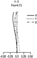
Fig. 2 A-4C shows the separately aberration diagram according to the zoom lens of present technique the first embodiment.Fig. 2 A-2C is that illustration is according to the figure of the aberration on the wide-angle side of the zoom lens of present technique the first embodiment.Fig. 3 A-3C is illustration according to the figure of the aberration on the wide-angle side of the zoom lens of present technique the first embodiment and the middle focal length between the end of dolly-out,ing dolly-back.Fig. 4 A-4C is that illustration is according to the figure of the aberration on the end of dolly-out,ing dolly-back of the zoom lens of present technique the first embodiment.Fig. 2 A, 3A and 4A show spherical aberration figure, and Fig. 2 B, 3B and 4B show astigmatism figure, and Fig. 2 C, 3C and 4C show distortion map.
Notice that in each spherical aberration figure, solid line represents the value on the d line (wavelength of 587.6nm), dotted line represents the value on the c line (wavelength of 656.3nm), and dot-and-dash line represents the value on the g line (435.8nm).In addition, in each astigmatism figure, solid line S represents the value of sagittal image surface (sagittal image plane), and dotted line M shows the value of meridianal image surface (meridional image plane).
<2. the second embodiment 〉
[lens configuration]
Fig. 5 is that illustration is according to the figure of the lens configuration of the zoom lens of present technique the second embodiment.Similar with the first embodiment of above-mentioned present technique, comprise successively to image planes IMG from object side according to the zoom lens of present technique the second embodiment: the first lens group G1 with positive refracting power; The second lens combination G2 with negative refraction power; And the 3rd lens combination G3 with positive refracting power.That is to say that the second embodiment of present technique is different aspect the example of special value, but has the essentially identical configuration with above-mentioned present technique the first embodiment.
[zoom lens data]
Table 3 shows according to present technique the second embodiment, has used the lens data of numerical example 2 of the zoom lens of special value.
Table 3
| Surface number | R | D | Nd | vd |
| 1 | 88.889 | 5.055 | 1.618000 | 63.39 |
| 2 | 15408.713 | 0.150 | ||
| 3 | 78.897 | 2.151 | 1.90366 | 31.32 |
| 4 | 45.823 | 6.921 | 1.48749 | 70.44 |
| 5 | 552.805 | D5 | ||
| 6 | -488.152 | 1.100 | 1.72916 | 54.67 |
| 7 | 22.026 | 2.636 | 1.92286 | 20.88 |
| 8 | 40.444 | 3.913 | ||
| 9 | -41.051 | 1.100 | 1.83481 | 42.72 |
| 10 | -522.434 | D10 | ||
| 11 | 30.200 | 4.886 | 1.48749 | 70.44 |
| 12 | -81.651 | 0.150 | ||
| 13 | 61.882 | 2.500 | 1.618000 | 63.39 |
| 14 | -500.000 | 1.500 | ||
| 15 | Aperture diaphragm | 0.500 | ||
| 16 | 30.966 | 2.444 | 1.49700 | 81.61 |
| 17 | 170.272 | 1.381 | ||
| 18 | -64.852 | 1.000 | 1.84666 | 23.78 |
| 19 | 110.778 | 15.168 | ||
| 20 | 52.727 | 2.907 | 1.68893 | 31.16 |
| 21 | -22.941 | 0.700 | 1.83481 | 42.72 |
| 22 | 20.000 | 6.900 | ||
| 23 | 34.081 | 2.500 | 1.59551 | 39.22 |
| 24 | -374.351 |
In the second embodiment of present technique, when lens position changes to when end of dolly-out,ing dolly-back, the spatial variations of lens combination as described below from wide-angle side.That is to say that these spaces are space D5 between first lens group G1 and the second lens combination G2 and the space D10 between the second lens combination G2 and the 3rd lens combination G3.Table 4 shows the separately value of open F value Fno, focal distance f, half angle of view ω and space D5 and D10 on wide-angle side (f=56.6), middle focal length (f=150.0) and the end (f=291.0) of dolly-out,ing dolly-back.
Table 4
| Fno | 4.00 | 4.73 | 6.43 |
| f | 56.6 | 150.0 | 291.0 |
| ω | 14.5 | 5.3 | 2.8 |
| D5 | 5.000 | 39.732 | 46.573 |
| D10 | 37.769 | 17.050 | 1.000 |
[aberrations of zoom lens]
Fig. 6 A-8C shows the separately aberration diagram according to the zoom lens of present technique the second embodiment.Fig. 6 A-6C is that illustration is according to the figure of the aberration on the wide-angle side of the zoom lens of present technique the second embodiment.Fig. 7 A-7C is illustration according to the figure of the aberration on the wide-angle side of the zoom lens of present technique the second embodiment and the middle focal length between the end of dolly-out,ing dolly-back.Fig. 8 A-8C is that illustration is according to the figure of the aberration on the end of dolly-out,ing dolly-back of the zoom lens of present technique the second embodiment.Fig. 6 A, 7A and 8A show spherical aberration figure, and Fig. 6 B, 7B and 8B show astigmatism figure, and Fig. 6 C, 7C and 8C show distortion map.Note identical with described in present technique the first embodiment of the line style in each aberration diagram.
<3. the 3rd embodiment 〉
[lens configuration]
Fig. 9 is that illustration is according to the figure of the lens configuration of the zoom lens of present technique the 3rd embodiment.Similar with the first embodiment of above-mentioned present technique, comprise successively to image planes IMG from object side according to the zoom lens of present technique the 3rd embodiment: the first lens group G1 with positive refracting power; The second lens combination G2 with negative refraction power; And the 3rd lens combination G3 with positive refracting power.That is to say that the 3rd embodiment of present technique is different aspect the example of special value, but has the essentially identical configuration with above-mentioned present technique the first embodiment.
[zoom lens data]
Table 5 shows according to present technique the 3rd embodiment, has used the lens data of numerical example 3 of the zoom lens of special value.
Table 5
| Surface number | R | D | Nd | vd |
| 1 | 91.105 | 5.253 | 1.618000 | 63.39 |
| 2 | -2630.060 | 0.150 | ||
| 3 | 79.093 | 2.198 | 1.90366 | 31.32 |
| 4 | 45.902 | 7.000 | 1.48749 | 70.44 |
| 5 | 516.215 | D5 | ||
| 6 | -230.970 | 1.100 | 1.74330 | 49.22 |
| 7 | 22.067 | 3.003 | 1.92286 | 20.88 |
| 8 | 49.229 | 3.374 | ||
| 9 | -48.394 | 1.100 | 1.83400 | 37.34 |
| 10 | 390.797 | D10 | ||
| 11 | 31.812 | 4.575 | 1.49700 | 81.61 |
| 12 | -85.256 | 0.150 | ||
| 13 | 57.578 | 2.500 | 1.618000 | 63.39 |
| 14 | -500.000 | 1.500 | ||
| 15 | Aperture diaphragm | 0.500 | ||
| 16 | 32.561 | 2.144 | 1.49700 | 81.61 |
| 17 | 114.513 | 1.453 | ||
| 18 | -69.713 | 1.000 | 1.84666 | 23.78 |
| 19 | 176.408 | 15.504 | ||
| 20 | 69.529 | 2.991 | 1.69895 | 30.05 |
| 21 | -20.879 | 0.700 | 1.83400 | 37.34 |
| 22 | 20.000 | 6.486 | ||
| 23 | 33.895 | 2.500 | 1.63980 | 34.57 |
| 24 | -196.930 |
In the 3rd embodiment of present technique, when lens position changes to when end of dolly-out,ing dolly-back, the spatial variations of lens combination as described below from wide-angle side.That is to say that these spaces are space D5 between first lens group G1 and the second lens combination G2 and the space D10 between the second lens combination G2 and the 3rd lens combination G3.Table 6 shows the separately value of open F value Fno, focal distance f, half angle of view ω and space D5 and D10 on wide-angle side (f=56.6), middle focal length (f=151.8) and the end (f=291.0) of dolly-out,ing dolly-back.
Table 6
| Fno | 4.11 | 4.82 | 6.31 |
| f | 56.6 | 151.8 | 291.0 |
| ω | 14.4 | 5.2 | 2.8 |
| D5 | 5.000 | 39.779 | 47.242 |
| D10 | 41.086 | 18.664 | 1.000 |
[aberrations of zoom lens]
Figure 10 A-12C shows the separately aberration diagram according to the zoom lens of present technique the 3rd embodiment.Figure 10 A-10C is that illustration is according to the figure of the aberration on the wide-angle side of the zoom lens of present technique the 3rd embodiment.Figure 11 A-11C is illustration according to the figure of the aberration on the wide-angle side of the zoom lens of present technique the 3rd embodiment and the middle focal length between the end of dolly-out,ing dolly-back.Figure 12 A-12C is that illustration is according to the figure of the aberration on the end of dolly-out,ing dolly-back of the zoom lens of present technique the 3rd embodiment.Figure 10 A, 11A and 12A show spherical aberration figure, and Figure 10 B, 11B and 12B show astigmatism figure, and Figure 10 C, 11C and 12C show distortion map.Note identical with described in present technique the first embodiment of the line style in each aberration diagram.
<4. the 4th embodiment 〉
[lens configuration]
Figure 13 is that illustration is according to the figure of the lens configuration of the zoom lens of present technique the 4th embodiment.Similar with the first embodiment of above-mentioned present technique, comprise successively to image planes IMG from object side according to the zoom lens of present technique the 4th embodiment: the first lens group G1 with positive refracting power; The second lens combination G2 with negative refraction power; And the 3rd lens combination G3 with positive refracting power.That is to say that the 4th embodiment of present technique is different aspect the example of special value, but has the essentially identical configuration with above-mentioned present technique the first embodiment.
[zoom lens data]
Table 7 shows according to present technique the 4th embodiment, has used the lens data of numerical example 3 of the zoom lens of special value.
Table 7
| Surface number | R | D | Nd | vd |
| 1 | 95.119 | 4.840 | 1.618000 | 63.39 |
| 2 | 8514.703 | 0.150 | ||
| 3 | 83.818 | 2.733 | 1.90366 | 31.32 |
| 4 | 48.939 | 6.585 | 1.48749 | 70.44 |
| 5 | 550.832 | D5 | ||
| 6 | -213.809 | 1.100 | 1.74330 | 49.22 |
| 7 | 22.530 | 2.828 | 1.92286 | 20.88 |
| 8 | 46.390 | 3.497 | ||
| 9 | -46.254 | 1.100 | 1.83481 | 42.72 |
| 10 | 2604.067 | D10 | ||
| 11 | 118.873 | 2.467 | 1.48749 | 70.44 |
| 12 | -71.924 | 0.150 | ||
| 13 | 44.422 | 2.635 | 1.618000 | 63.39 |
| 14 | -413.258 | 1.500 | ||
| 15 | Aperture diaphragm | 0.500 | ||
| 16 | 33.032 | 3.832 | 1.49700 | 81.61 |
| 17 | -111.891 | 0 | ||
| 18 | -110.587 | 1.000 | 1.84666 | 23.78 |
| 19 | 91.406 | 17.593 | ||
| 20 | 42.099 | 2.073 | 1.75211 | 25.05 |
| 21 | -89.195 | 0.845 | 1.83481 | 42.72 |
| 22 | 19.239 | 12.420 | ||
| 23 | 34.897 | 2.237 | 1.49700 | 81.61 |
| 24 | 137.983 |
In the 4th embodiment of present technique, when lens position changes to when end of dolly-out,ing dolly-back, the spatial variations of lens combination as described below from wide-angle side.That is to say that these spaces are space D5 between first lens group G1 and the second lens combination G2 and the space D10 between the second lens combination G2 and the 3rd lens combination G3.Table 8 shows the separately value of open F value Fno, focal distance f, half angle of view ω and space D5 and D10 on wide-angle side (f=56.6), middle focal length (f=150.0) and the end (f=291.0) of dolly-out,ing dolly-back.
Table 8
| Fno | 4.16 | 4.65 | 6.15 |
| f | 56.6 | 150.0 | 291.0 |
| ω | 14.5 | 5.3 | 2.8 |
| D5 | 5.000 | 46.534 | 54.177 |
| D10 | 36.911 | 17.811 | 1.000 |
[aberrations of zoom lens]
Figure 14 A-16C shows the separately aberration diagram according to the zoom lens of present technique the 4th embodiment.Figure 14 A-14C is that illustration is according to the figure of the aberration on the wide-angle side of the zoom lens of present technique the 4th embodiment.Figure 15 A-15C is illustration according to the figure of the aberration on the wide-angle side of the zoom lens of present technique the 4th embodiment and the middle focal length between the end of dolly-out,ing dolly-back.Figure 16 A-16C is that illustration is according to the figure of the aberration on the end of dolly-out,ing dolly-back of the zoom lens of present technique the 4th embodiment.Figure 14 A, 15A and 16A show spherical aberration figure, and Figure 14 B, 15B and 16B show astigmatism figure, and Figure 14 C, 15C and 16C show distortion map.Note identical with described in present technique the first embodiment of the line style in each aberration diagram.
[summary of conditional expression]
Table 9 shows the separately numerical value of the numerical example 1-4 of present technique the first to the 4th embodiment.Can clearly be seen that from these numerical value conditional expression (1)-(5) all are met.In addition, from each aberration diagram, can find out, on wide-angle side, wide-angle side and the dolly-out, dolly-back middle focal length between the end and the end of dolly-out,ing dolly-back, proofread and correct evenly various aberrations.
Table 9

<5. example application 〉
[configuration of imaging device]
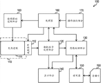
Figure 17 is illustration according to the zoom lens applications of present technique the first to the 4th embodiment in the figure of the example of imaging device 100.Imaging device 100 comprises camera block 110; Camera signal processing section 120; Image processing section 130; Display part 140; Read write line 150; Processor 160; Operation receiving unit 170; And lens drive control part 180.
Camera signal processing section 120 is configured to the signal of picture signal as analog-to-digital conversion process of catching processed.Camera signal processing section 120 will convert digital signal to from the output signal of image device 112 outputs.In addition, camera signal processing section 120 carries out processing as noise elimination, image quality correction, various types of signals of converting to the processing of YUV.
Read write line 150 access storage cards 190 are in order to read and write picture signal.Read write line 150 will write in the storage card 190 by the view data of image processing section 130 codings, reads in addition the view data that is recorded in the storage card 190.Storage card 190 is, for example, from slot that read write line 150 is connected removable semiconductor memory.
Lens drive control part 180 is configured to control the driving that is arranged in the lens in the camera block 110.Lens drive control part 180 drives the motor (not illustrating in the drawings) of each lens in the zoom lens 111 according to the control signal control that comes self processor 160.
In imaging device 100, when waiting for shooting, the image signal output of camera block 110 being caught under the control of processor 160 by camera signal processing section 120 is to the display part 140, in order to be shown as camera scioptics image (camera through-the-lens image).In addition, when carrying out the operation instruction signal of zoom from 170 inputs of operation receiving unit, processor 160 outputs to lens drive control part 180 with control signal, and according to the predetermined lens in the mobile zoom lens 111 of the control of lens drive control part 180.
When operation receiving unit 170 receives shutter operation, the picture signal of catching is outputed to image processing section 130 from camera signal processing section 120, carry out the coding for compression, and convert the numerical data of tentation data form to.Translation data is outputed to read write line 150, and write on the storage card 190.
For example, when partly pressing in order to record (shooting) or during the shutter release button of full push receiving unit 170, focusing on.In this case, according to the control signal that receives from processor 160, lens drive control part 180 moves the predetermined lens of zoom lens 111.
In the situation of the view data on the storage card 190, the predetermined image data are read in the operation that read write line 150 operation response receiving units 170 receive from storage card 190 at reproducing.Then, the view data of reading by image processing section 130 decoding to be to carry out decompress(ion), after this with the image signal output that reproduces to display part 140, thereby the image of display reproduction.
Note, described the embodiment of present technique for the situation that imaging device 100 is applied to digital camera.But the range of application of imaging device 100 is not limited to digital camera, and this device also can be widely used in the digital input/output device as Digital Video.
As described above, according to the embodiment of present technique, the positive lens groups GF that consists of the 3rd lens combination is arranged within the preset range with the ratio that is arranged to as the focal length of the near negative lens group GR of side joint.Thus, arrange the aperture of the 3rd lens combination less, the size that therefore can dwindle whole zoom lens.That is to say, can realize having outstanding imaging performance, compactedness, low cost and zoom ratio greater than five times and on the end focal length of dolly-out,ing dolly-back at about 450 millimeters nominal values under the 35 mm film equivalents half angle of view less than the lens of 3 ° focal range.
Notice that above-described embodiment of present technique shows the example that embodies present technique, so the project among the embodiment of present technique corresponds respectively to the specific project of the appended claims in the present technique.Equally, the specific project of appended claims corresponds respectively to the project that represents by the same names among the embodiment of present technique.But present technique is not limited to the embodiment of present technique, embodies but can do various modifications to embodiment by the present technique scope ground that does not depart from present technique.
(1) a kind of zoom lens comprise successively from object side: the first lens group with positive refracting power; The second lens combination with negative refraction power; And the 3rd lens combination with positive refracting power,
Wherein, during the zoom from wide-angle side to the end of dolly-out,ing dolly-back, carry out zoom by the space that changes the first to the 3rd lens combination,
Wherein, described the 3rd lens combination comprises successively the positive lens groups with positive refracting power and is arranged near it as side and have the negative lens group of negative refraction power from object side, intervenient is the widest air gap in the 3rd lens combination, and wherein satisfies following conditional expression (1):
(1)-0.45<fGF/fGR<-0.10,
Wherein,
FGF is the focal length of described positive lens groups, and
FGR is the focal length of described negative lens group.
(2) according to (1) described zoom lens, wherein further satisfy following conditional expression (2):
(2)0.1<L3/ft<0.2,
Wherein,
L3 is the length of described the 3rd lens combination on optical axis, and
Ft is the focal length of whole system on the end of dolly-out,ing dolly-back of described zoom lens.
(3) according to (1) or (2) described zoom lens, the described negative lens group that wherein consists of described the 3rd lens combination comprise be arranged to the most approaching with object side, have negative refraction power and by the positive lens that protrudes towards object side and the balsaming lens that forms towards the recessed negative lens of picture side, and wherein satisfy following conditional expression (3) and (4):
(3)0.2<(RLR1-RLR2)/(RLR1+RLR2)<0.8,
(4)ndLR2>1.72,
Wherein,
RLR1 is the radius-of-curvature on described balsaming lens and the immediate surface of object side,
RLR2 is the radius-of-curvature on described balsaming lens and the immediate surface of picture side, and
NdLR2 is the refractive index of negative lens on the d line.
(4) according to any one described zoom lens of (1) to (3), wherein further satisfy following conditional expression (5):
(5)vdp/vdn>1.18,
Wherein,
Vdp is the Abbe number of positive lens on the d line that consists of described balsaming lens, and
Vdn is the Abbe number of negative lens on the d line that consists of described balsaming lens.
(5) according to (1) to any one described zoom lens of (4), the described negative lens group that wherein consists of described the 3rd lens combination comprises having negative refraction power and by the positive lens that protrudes towards object side and the balsaming lens and the second positive lens that form towards the recessed negative lens of picture side successively from object side.
(6) according to any one described zoom lens of (1) to (5), further comprise the lens that do not have actual forces (power).
(7) a kind of imaging device comprises:
Zoom lens, it comprises the first lens group with positive refracting power, the 3rd lens combination that has the second lens combination of negative refraction power and have positive refracting power successively from object side; And
Image device is used for and will converts electric signal to by the light image that described zoom lens form,
Wherein, described zoom lens carry out zoom by the space that changes the first to the 3rd lens combination during the zoom from wide-angle side to the end of dolly-out,ing dolly-back,
Wherein, described the 3rd lens combination comprises successively the positive lens groups with positive refracting power and is arranged near it as side and have the negative lens group of negative refraction power from object side, intervenient is the widest air gap in the 3rd lens combination, and wherein satisfies following conditional expression (1):
(1)-0.45<fGF/fGR<-0.10,
Wherein,
FGF is the focal length of described positive lens groups, and
FGR is the focal length of described negative lens group.
(8) according to (7) described imaging device, wherein said zoom lens further comprise the lens that do not have actual forces.
The disclosure comprises and is disclosed on June 28th, 2011 to the relevant theme of the theme among the Japanese priority patent application JP2011-142615 of Japan Office submission, is incorporated herein by reference in its entirety.
Those of ordinary skill in the art should be understood that as long as within the scope of appended claims or its equivalent, depends on designing requirement and other factors, can make various modifications, combination, sub-portfolio and change.
Claims (6)
1. zoom lens comprise successively from object side:
First lens group with positive refracting power;
The second lens combination with negative refraction power; And
The 3rd lens combination with positive refracting power,
Wherein, during the zoom from wide-angle side to the end of dolly-out,ing dolly-back, carry out zoom by the space that changes the first to the 3rd lens combination,
Wherein, described the 3rd lens combination comprises the positive lens groups with positive refracting power and is arranged near it as side and have the negative lens group of negative refraction power that from object side intervenient is the widest air gap in the 3rd lens combination successively, and
Wherein satisfy following conditional expression (1):
(1)-0.45<fGF/fGR<-0.10,
Wherein,
FGF is the focal length of described positive lens groups, and
FGR is the focal length of described negative lens group.
2. according to zoom lens claimed in claim 1, wherein further satisfy following conditional expression (2):
(2)0.1<L3/ft<0.2,
Wherein,
L3 is the length of described the 3rd lens combination on optical axis, and
Ft is the focal length of whole system on the end of dolly-out,ing dolly-back of described zoom lens.
3. according to zoom lens claimed in claim 2,
The described negative lens group that wherein consists of described the 3rd lens combination comprise be arranged to the most approaching with object side, have negative refraction power and by the positive lens that protrudes towards object side and the balsaming lens that forms towards the recessed negative lens of picture side, and
Wherein satisfy following conditional expression (3) and (4):
(3) 0.2<(RLR1-RLR2)/(RLR1+RLR2)<0.8, and
(4)ndLR2>1.72,
Wherein,
RLR1 is the radius-of-curvature on described balsaming lens and the immediate surface of object side,
RLR2 is the radius-of-curvature on described balsaming lens and the immediate surface of picture side, and
NdLR2 is the refractive index of negative lens on the d line.
4. according to zoom lens claimed in claim 3, wherein further satisfy following conditional expression (5):
(5)vdp/vdn>1.18,
Wherein,
Vdp is the Abbe number of positive lens on the d line that consists of described balsaming lens, and
Vdn is the Abbe number of negative lens on the d line that consists of described balsaming lens.
5. according to 2 described zoom lens, the described negative lens group that wherein consists of described the 3rd lens combination comprises having negative refraction power and by the positive lens that protrudes towards object side and the balsaming lens and the second positive lens that form towards the recessed negative lens of picture side successively from object side.
6. imaging device comprises:
Zoom lens, it comprises the first lens group with positive refracting power, the 3rd lens combination that has the second lens combination of negative refraction power and have positive refracting power successively from object side; And
Image device is used for and will converts electric signal to by the light image that described zoom lens form,
Wherein, described zoom lens carry out zoom by the space that changes the first to the 3rd lens combination during the zoom from wide-angle side to the end of dolly-out,ing dolly-back,
Wherein, described the 3rd lens combination comprises the positive lens groups with positive refracting power and is arranged near it as side and have the negative lens group of negative refraction power that from object side intervenient is the widest air gap in the 3rd lens combination successively, and
Wherein satisfy following conditional expression (1):
(1)-0.45<fGF/fGR<-0.10,
Wherein,
FGF is the focal length of described positive lens groups, and
FGR is the focal length of described negative lens group.
Applications Claiming Priority (2)
| Application Number | Priority Date | Filing Date | Title |
|---|---|---|---|
| JP2011-142615 | 2011-06-28 | ||
| JP2011142615A JP2013011641A (en) | 2011-06-28 | 2011-06-28 | Zoom lens and imaging apparatus |
Publications (1)
| Publication Number | Publication Date |
|---|---|
| CN102854613A true CN102854613A (en) | 2013-01-02 |
Family
ID=47390426
Family Applications (1)
| Application Number | Title | Priority Date | Filing Date |
|---|---|---|---|
| CN2012102158171A Pending CN102854613A (en) | 2011-06-28 | 2012-06-27 | Zoom lens and imaging apparatus |
Country Status (3)
| Country | Link |
|---|---|
| US (1) | US8896932B2 (en) |
| JP (1) | JP2013011641A (en) |
| CN (1) | CN102854613A (en) |
Families Citing this family (6)
| Publication number | Priority date | Publication date | Assignee | Title |
|---|---|---|---|---|
| DE112013004313B4 (en) * | 2012-08-29 | 2016-09-15 | Fujifilm Corporation | Imaging lens and imaging device |
| TWI518357B (en) * | 2014-02-26 | 2016-01-21 | 信泰光學(深圳)有限公司 | Lens assembly |
| JP6354257B2 (en) * | 2014-03-27 | 2018-07-11 | 株式会社ニコン | Variable magnification optical system and imaging apparatus |
| WO2015146176A1 (en) | 2014-03-27 | 2015-10-01 | 株式会社ニコン | Variable power optical system, imaging device, and variable power optical system production method |
| EP3026480A1 (en) * | 2014-11-28 | 2016-06-01 | Canon Kabushiki Kaisha | Zoom lens and image pickup apparatus including the same |
| US10908400B2 (en) * | 2016-12-09 | 2021-02-02 | Canon Kabushiki Kaisha | Zoom lens, image pickup apparatus including the same, and control device for the same |
Citations (4)
| Publication number | Priority date | Publication date | Assignee | Title |
|---|---|---|---|---|
| JPH1096857A (en) * | 1996-09-24 | 1998-04-14 | Asahi Optical Co Ltd | Zoom lens |
| US6014266A (en) * | 1997-07-22 | 2000-01-11 | Nikon Corporation | Zoom lens focusing system and method |
| CN1603876A (en) * | 2003-09-29 | 2005-04-06 | 株式会社尼康 | Zoom lens system |
| CN1841115A (en) * | 2005-03-30 | 2006-10-04 | 株式会社尼康 | Zoom lens system |
Family Cites Families (5)
| Publication number | Priority date | Publication date | Assignee | Title |
|---|---|---|---|---|
| US6778331B2 (en) * | 2002-05-10 | 2004-08-17 | Pentax Corporation | Zoom lens system |
| JP2004029765A (en) | 2002-05-10 | 2004-01-29 | Pentax Corp | Zoom lens system |
| JP4994796B2 (en) | 2006-11-14 | 2012-08-08 | キヤノン株式会社 | Zoom lens and imaging apparatus having the same |
| JP4706940B2 (en) * | 2009-02-10 | 2011-06-22 | ソニー株式会社 | Zoom lens and imaging device |
| JP5574796B2 (en) * | 2010-04-19 | 2014-08-20 | キヤノン株式会社 | Zoom lens and imaging apparatus having the same |
-
2011
- 2011-06-28 JP JP2011142615A patent/JP2013011641A/en not_active Abandoned
-
2012
- 2012-05-23 US US13/478,824 patent/US8896932B2/en not_active Expired - Fee Related
- 2012-06-27 CN CN2012102158171A patent/CN102854613A/en active Pending
Patent Citations (4)
| Publication number | Priority date | Publication date | Assignee | Title |
|---|---|---|---|---|
| JPH1096857A (en) * | 1996-09-24 | 1998-04-14 | Asahi Optical Co Ltd | Zoom lens |
| US6014266A (en) * | 1997-07-22 | 2000-01-11 | Nikon Corporation | Zoom lens focusing system and method |
| CN1603876A (en) * | 2003-09-29 | 2005-04-06 | 株式会社尼康 | Zoom lens system |
| CN1841115A (en) * | 2005-03-30 | 2006-10-04 | 株式会社尼康 | Zoom lens system |
Also Published As
| Publication number | Publication date |
|---|---|
| US20130003191A1 (en) | 2013-01-03 |
| JP2013011641A (en) | 2013-01-17 |
| US8896932B2 (en) | 2014-11-25 |
Similar Documents
| Publication | Publication Date | Title |
|---|---|---|
| US7742236B2 (en) | Zoom lens and image pickup apparatus | |
| JP4059146B2 (en) | Zoom lens and imaging device | |
| JP4771182B2 (en) | Zoom lens and imaging device | |
| US20110273780A1 (en) | Zoom lens and imaging apparatus | |
| US8649107B2 (en) | Zoom lens and imaging apparatus | |
| US9316822B2 (en) | Zoom lens and imaging apparatus | |
| US7880974B2 (en) | Zoom lens and imaging apparatus | |
| US20110194015A1 (en) | Zoom lens and imaging apparatus | |
| WO2016056310A1 (en) | Wide angle lens and image pickup device | |
| JP2011107450A (en) | Imaging lens and imaging apparatus | |
| JP4697555B2 (en) | Zoom lens and imaging device | |
| JP2015064492A (en) | Zoom lens and imaging apparatus | |
| WO2018139160A1 (en) | Zoom lens and imaging device | |
| JP4697556B2 (en) | Zoom lens and imaging device | |
| JP2009217167A (en) | Zoom optical system and imaging apparatus | |
| CN102854613A (en) | Zoom lens and imaging apparatus | |
| JP2006113257A (en) | Zoom lens and imaging apparatus | |
| JP5854228B2 (en) | Imaging lens and imaging device | |
| US20240061211A1 (en) | Imaging lens and imaging apparatus | |
| US8760770B2 (en) | Zoom lens and imaging apparatus | |
| US20120327518A1 (en) | Zoom lens and imaging apparatus | |
| JP5003174B2 (en) | Zoom lens and imaging apparatus | |
| US8289625B2 (en) | Zoom lens and imaging apparatus | |
| JP2011164195A (en) | Zoom lens and imaging apparatus | |
| JP2011022380A (en) | Zoom lens and imaging apparatus |
Legal Events
| Date | Code | Title | Description |
|---|---|---|---|
| C06 | Publication | ||
| PB01 | Publication | ||
| C10 | Entry into substantive examination | ||
| SE01 | Entry into force of request for substantive examination | ||
| C02 | Deemed withdrawal of patent application after publication (patent law 2001) | ||
| WD01 | Invention patent application deemed withdrawn after publication |
Application publication date: 20130102 |