CN102839835B - Full-automatic folding garage - Google Patents
Full-automatic folding garage Download PDFInfo
- Publication number
- CN102839835B CN102839835B CN201210349560.9A CN201210349560A CN102839835B CN 102839835 B CN102839835 B CN 102839835B CN 201210349560 A CN201210349560 A CN 201210349560A CN 102839835 B CN102839835 B CN 102839835B
- Authority
- CN
- China
- Prior art keywords
- driving mechanism
- back segment
- full automatic
- automatic folding
- main
- Prior art date
- Legal status (The legal status is an assumption and is not a legal conclusion. Google has not performed a legal analysis and makes no representation as to the accuracy of the status listed.)
- Expired - Fee Related
Links
Images


Abstract
The invention relates to a full-automatic folding garage which comprises a folding framework, film cloth arranged on the folding framework, a driving system for driving the folding framework, and a power system for supplying power to the driving system, wherein the folding framework comprises a first main framework, a second main framework and a plurality of auxiliary frameworks; the driving system comprises a rear section driving mechanism and a middle section driving mechanism; a first end of the first main framework is connected with the rear section driving mechanism, and a driving shaft parallel to a working face; the first main framework rotates around the axis of the driving shaft driven by the rear section driving mechanism; a second end of the first main framework, second ends of the auxiliary frameworks, and a second end of the second main framework are rotationally connected in sequence; and the middle section driving mechanism is arranged at the second end of the second main framework. The full-automatic folding garage is convenient to install and convenient and quick to use, has smaller limitation on a vehicle when the vehicle parks, can provide comprehensive protection for an automobile, and is fashionable in appearance and wide in application scope.
Description
Technical field
The present invention relates to a kind of for covering and protect the Full automatic folding garage of automobile.
Background technology
The existing garage for automobile protective has middle-set-type, half receipts formula and wheel-track type etc. several conventionally.Middle-set-type garage comprises the many support bars that are hinged, and the hinged place of support bar is arranged on ground.In the time that garage is packed up, the support bar of both sides is packed up and forms arch to central support bar.In the time that automobile sails garage into, need part vehicle body pass and come to a complete stop in the middle of the support bar of arch, then support bar is put down by the both sides of mediad central branches strut and covers automobile.It uses comparatively inconvenience, and the restriction to automobile in the time parking is larger.Support frame and the middle-set-type of partly receiving formula garage are similar, but it is in the time packing up, and the support bar of a side rotates to the support bar of opposite side, until all support bar mutually folding near and lie against on ground.When it is packed up, floor space is larger.Above-mentioned two kinds of garages are subject to the restriction of both sides, left and right, garage parts in the time parking, and turn to adjusting range less.And wheel-track type garage when mounted, need to lay in advance on the ground wheel track, and below garage skeleton, roller is set.Garage launches or while packing up, and garage skeleton drives film cloth etc. along Wheel/rail and by Car covening, its comparatively inconvenience is installed and cost higher.
Summary of the invention
The object of this invention is to provide a kind of installation, easy to use and can better protect the Full automatic folding garage of automobile.
For achieving the above object, the technical solution used in the present invention is:
A kind of Full automatic folding garage, be arranged on its work plane for cover and protect automobile, described Full automatic folding garage to comprise folding frame, be arranged at film cloth on described folding frame, drive drive system that described folding frame packs up or open, be the dynamical system that power is provided of described drive system;
Described folding frame comprises the first main framing, second main rib frame, some secondary skeletons all with first end and the second end; Described drive system comprises back segment driving mechanism and stage casing driving mechanism;
The first end of the first described main framing is connected with described back segment driving mechanism, the first end of the first described main framing is connected with the driving shaft paralleling with described work plane, and the first described main framing axis around described driving shaft under the driving of described back segment driving mechanism rotates;
The connection that rotates successively of the second end of the second end of the second end of the first described main framing, described secondary skeleton, described second main rib frame, and this axis being rotationally connected parallels with described work plane; The first end of the first end of the first end of the first main framing described in described film cloth is connected in, described secondary skeleton, described second main rib frame; Described stage casing driving mechanism is arranged at the second end of described second main rib frame, and described second main rib frame rotates around the described axis being rotationally connected under the driving of described stage casing driving mechanism;
Described Full automatic folding garage has collapsed state, intermediateness and open mode; Under described collapsed state, the first end of the first described main framing is near described work plane, and the second end of the first described main framing extends to the superjacent air space of described work plane, the first end of the first end of the first end of the first described main framing, described secondary skeleton, described second main rib frame mutually near and described film cloth folding; Under described intermediateness, the first described main framing is parallel to be placed on described work plane; In described open mode, the first described main framing and all parallel being placed on described work plane of described second main rib frame, described film cloth along the expansion direction of described folding frame extend and and described work plane between form the space, garage that holds automobile, described secondary skeleton is at the film cloth described in described space, garage inner support.
Preferably, the other end of described back segment driving mechanism comprises back segment drive motors, the screw rod being in transmission connection mutually with described back segment drive motors, the link block being threaded mutually with described screw rod, one end and described link block rotate to be connected first connecting rod, one end and described first connecting rod is by the active connection third connecting rod being connected that rotates, the other end of described third connecting rod and described driving shaft are fixedly connected, axially axially perpendicular with described driving shaft of described screw rod.
Preferably, the first rocking arm that gearbox that described back segment driving mechanism comprises back segment drive motors, be in transmission connection mutually with described back segment drive motors, one end are connected with the output shaft of described gearbox, one end and the other end of described the first rocking arm second connecting rod that is connected, one end and the other end of described second connecting rod the second rocking arm being connected that rotates that rotates, the other end of the second described rocking arm and described driving shaft are fixedly connected; The first described rocking arm, described second connecting rod, the second described rocking arm form three-link mechanism, and the plane at described three-link mechanism place and described driving shaft is axially perpendicular.
Preferably, between described back segment drive motors and described screw rod or between described back segment drive motors and described gearbox, be in transmission connection mutually by belt or chain, on the power shaft of described screw rod or described gearbox, be provided with and the belt wheel of its coaxial rotation, between described belt wheel and the output shaft of described back segment drive motors, be connected by described belt or the chain of closed circular.
Preferably, described stage casing driving mechanism comprises stage casing drive motors, be arranged on the output shaft of described stage casing drive motors and with the pinion of its coaxial rotation, be arranged at the arc-shaped rack on described second main rib frame, described pinion is meshed with described arc-shaped rack.
Preferably, described dynamical system is solar energy system, it comprises solar panel, the battery being connected with described solar panel, the controller being connected with described battery with described solar panel, and described battery is connected with described stage casing driving mechanism with described back segment driving mechanism respectively by the on-off control system being made up of with relay limit switch.
Preferably, the first described main framing is two and parallels setting, the two ends of the driving shaft described in the main framing described in two is connected to; Described secondary skeleton and described second main rib frame are U-shaped bar, it comprises that two parallel the first bar of setting and the second bar that one end of the first bar described in two is connected, the first end of the first end of described secondary skeleton or described second main rib frame is one end that is connected with the second described bar of described the first bar, the second end of the second end of described secondary skeleton or described second main rib frame is the other end of described the first bar, i.e. one end of the oral area of the U-shaped described in the formation of the first described bar.
Preferably, on the secondary skeleton described in, be fixedly connected with a pair of positioning supporting rod.
Preferably, the place of being rotationally connected of the first described main framing, described secondary skeleton, described second main rib frame is provided with junction plate, and described stage casing driving mechanism is arranged on described junction plate, is also provided with buffer bar on described junction plate.
Preferably, on described film cloth, be provided with many elastic cords, in the same way, and described elastic cord is arranged between the secondary skeleton described in adjacent two the extension direction of the flexible direction of described elastic cord and described film cloth; On described film cloth, also offer unidirectional water seepage hole.
Full automatic folding garage of the present invention in use, comprises the process of packing up and expansion process., if desired park during in collapsed state at it, automobile is left to the front, garage of packing up.First start described rear end transmission mechanism, drive the first described main framing take described driving shaft as axis the direction to described work plane rotate, make described Full automatic folding garage in described intermediateness until the first described main framing is placed on described work plane completely.Then stop described rear end transmission mechanism and start described stage casing driving mechanism, and described second main rib frame is rotated further along the rotation direction of the first described main framing, until described second main rib frame is also placed on described work plane completely.In above-mentioned rotation process, the secondary skeleton described in each under the drive of described film cloth and rotate launch.Finally, described Full automatic folding garage is expanded to open mode, and described film cloth forms described space, garage under the support of the first described main framing, described secondary skeleton and described second main rib frame.And the process of packing up of described Full automatic folding garage is contrary with above-mentioned expansion process.First starting described stage casing driving mechanism makes described second main rib frame rotate to the direction of the first described main framing, make described secondary skeleton pack up and make described film cloth folding, until the running of described Full automatic folding garage is to described intermediateness simultaneously.Then start described rear end transmission mechanism, so that described folding frame rotates take described driving shaft as axis, until described folded state.
Because technique scheme is used; the present invention compared with prior art has following advantages: Full automatic folding garage of the present invention is easy for installation, easy to use; restriction to vehicle while parking is less; can provide omnibearing protection for automobile; it also has the outward appearance of fashion simultaneously, applied widely.
Accompanying drawing explanation
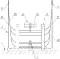
Accompanying drawing 1 is the front view of Full automatic folding garage of the present invention in deployed condition.
Accompanying drawing 2 is the top view of Full automatic folding garage of the present invention in deployed condition.
Accompanying drawing 3 is the left view of Full automatic folding garage of the present invention in deployed condition.
Accompanying drawing 4 is the right view of Full automatic folding garage of the present invention in deployed condition.
Accompanying drawing 5 is the left view of Full automatic folding garage of the present invention in collapsed state.
The partial front elevation view of the removal film cloth that accompanying drawing 6 is Full automatic folding garage of the present invention.
The front view of the back segment driving mechanism of the embodiment mono-that accompanying drawing 7 is Full automatic folding garage of the present invention.
The front view of the back segment driving mechanism of the embodiment bis-that accompanying drawing 8 is Full automatic folding garage of the present invention.
The front view of the stage casing driving mechanism that accompanying drawing 9 is Full automatic folding garage of the present invention.
The schematic diagram of the Manual drive mechanism that accompanying drawing 10 is Full automatic folding garage of the present invention.
The A portion zoomed-in view that accompanying drawing 11 is Full automatic folding garage of the present invention.
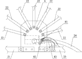
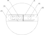
In above accompanying drawing: 1, ground; 2, folding frame; 21, the first main framing; 22, secondary skeleton; 23, second main rib frame; 231, Part I; 232, Part II; 24, buffer bar; 25, support bar; 3, film cloth; 4, dynamical system; 41, solar panel; 5, driving shaft; 6, junction plate; 7, back segment driving mechanism; 701, back segment drive motors; 702, screw rod; 703, first connecting rod; 704, belt wheel; 705, belt; 706, gearbox; 707, the first rocking arm; 708, second connecting rod; 709, the second rocking arm; 710, third connecting rod; 711, active connection; 8, stage casing driving mechanism; 81, stage casing drive motors; 82, pinion; 83, arc-shaped rack; 9, support; 10, manual snap close; 101, the first connecting shaft; 102, the second alignment pin; 103, the first alignment pin; 11, rocking handle.
The specific embodiment
Below in conjunction with embodiment shown in the drawings, the invention will be further described.
Embodiment mono-: referring to accompanying drawing 1 to shown in accompanying drawing 7 and accompanying drawing 9.
A kind of Full automatic folding garage, is arranged on its work plane for covering and protecting automobile.Conventionally this work plane is ground 1, is arranged on ground 1 by Full automatic folding garage.
Full automatic folding garage comprises folding frame 2, be arranged at film cloth 3 on folding frame 2, drive drive system that folding frame 2 packs up or open, be the dynamical system that power is provided 4 of drive system.
Folding frame 2 comprises that the first main framing 21, some secondary skeletons 22 and second main rib frame 23, the first main framings 21 comprise two and parallel setting.The first main framing 21 has first end and the second end, is connected with the axially driving shaft 5 parallel with ground 1 between the first end of two the first main framings 21.Secondary skeleton 22 and second main rib frame 23 are U-shaped bar, it comprises that two parallel the first bar of setting and the second bar that one end of two the first bars is connected, defining the first end of secondary skeleton 22 or the first end of second main rib frame 23 is one end that is connected with the second bar of the first bar, secondary the second end of skeleton 22 or the second end of second main rib frame 23 are the other end of the first bar, i.e. one end of the oral area of the formation U-shaped of the first bar.The second end of the second end of the first main framing 21, the second end of secondary skeleton 22, second main rib frame 23 rotates successively and is connected on junction plate 6, and this axis being rotationally connected parallels with ground 1.
Drive system comprises back segment driving mechanism 7 and stage casing driving mechanism 8.
Back segment driving mechanism 7 is arranged on support 9, back segment driving mechanism 7 comprises back segment drive motors 701, the screw rod 702 being in transmission connection mutually with back segment drive motors 701, the link block being threaded mutually with screw rod 702, one end and link block rotate to be connected first connecting rod 703, one end and first connecting rod 703 are by active connection 711 third connecting rod 710 being connected that rotates, the other end of third connecting rod 710 and driving shaft 5 are fixedly connected, screw rod 702 axially and driving shaft 5 axially perpendicular.Wherein, the two ends of link block are provided with connecting axle, and first connecting rod 703 is rotated and is connected with link block by connecting axle; Also be connecting axle and connect first connecting rod 703 with the active connection 711 of third connecting rod 710.Between back segment drive motors 701 and screw rod 702, be in transmission connection mutually by belt or chain, in the present embodiment, select belt 705 to connect.On screw rod 702, be provided with and the belt wheel 704 of its coaxial rotation, between belt wheel 704 and the output shaft of back segment drive motors 701, be connected by the belt 705 of closed circular.In the time that back segment drive motors 701 rotates, drive screw rod 702 to rotate by belt 705 and belt wheel 704.Because one end of first connecting rod 703 is threaded mutually with screw rod 702, therefore one end of first connecting rod 703 is along the moving axially of screw rod 702, thereby first connecting rod 703 drives driving shaft 5 to rotate, and driving shaft 5 drives the first main framing 21 to rotate take it as axis.
Stage casing driving mechanism 8 is arranged on junction plate 6, stage casing driving mechanism 8 comprises stage casing drive motors 81, be arranged on the output shaft of stage casing drive motors 81 and with the pinion 82 of its coaxial rotation, be arranged at the arc-shaped rack 83 on second main rib frame 23.Generally stage casing drive motors 81 is arranged to the inner side of junction plate 6, and other structures are arranged at the outside of junction plate 6.Arc-shaped rack 83 is extended to the direction of junction plate 6 by second main rib frame 23, and arc-shaped rack 83 is arranged on the hole wall of an arcuate socket, and pinion 82 is meshed with arc-shaped rack 83 through arcuate socket.In the time that stage casing drive motors 81 rotates, it drives pinion 82 rotate and pinion 82 is moved along arc-shaped rack 83, thereby drives second main rib frame 23 to rotate with the axis being rotationally connected.On junction plate 6, be also provided with buffer bar 24.
Full automatic folding garage has collapsed state, intermediateness and open mode.Under collapsed state, the first end of the first main framing 21 is near ground 1, and the second end of the first main framing 21 earthward 1 superjacent air space extends, the first end of the first end of the first main framing 21, the first end of secondary skeleton 22, second main rib frame 23 mutually close and film cloth 3 folds.Start back segment driving mechanism 7 so that the first main framing 21 take driving shaft 5 for axis 1 direction rotation earthward.In order to make the running of this Full automatic folding garage stable, can be fixedly installed two support bars 25 near on a certain secondary skeleton 22 of the first main framing 21, these two support bars 25 parallel setting, can adopt bow, its one end be fixedly connected with secondary skeleton 22 on, and the other end earthward 1 direction extend.In the process of above-mentioned expansion, support along with the first main framing 21 drives the rotation of secondary skeleton 22 and second main rib frame 23, support bar 25 first to touch ground 1 and form, and folding frame 2 continues expansion process, until the first main framing 21 is placed on ground 1.Now, the secondary skeleton 22 of part launches under the support of support bar 25, due to the setting of support bar 25, not only can stablize the motion process of this Full automatic folding garage, and first launch to avoid some support bar 25 to be pressed onto the automobile being stopped on parking space because it can make the secondary skeleton 25 of part.Especially generally, the support bar 25 that is positioned at middle part is set when longer compared with support bar 25 short and its both sides, the effect of its protection automobile is particularly remarkable.The Full automatic folding garage state that mediates.
Under intermediateness, first main framing 21 is parallel is placed on work plane.Now, stop back segment driving mechanism 7 and open stage casing driving mechanism 8.Start stage casing drive motors 81 and drive pinion 82 to rotate, and pinion 82 is moved along arc-shaped rack 83, can realize the rotation that drives second main rib frame 23.And buffer bar 24 on junction plate 6 can be realized buffering to this motion process.Along with the rotation of second main rib frame 23, each secondary skeleton 22 rotates successively and launches under the pulling of film cloth 3 and the elastic cord on it, makes Full automatic folding garage in deployed condition until second main rib frame 23 is placed on ground 1.Now, form the space, garage that holds automobile between film cloth 3 and work plane, secondary skeleton 22 is at space, garage inner support film cloth 3.
Unidirectional water seepage hole on film cloth 3 is arranged at film cloth 3 parts of the top in space, garage.Under this deployed condition, make if there is the situations such as rainfall outside space, garage that film cloth 3 is outer ponding, and unidirectional water seepage hole can prevent that water from flowing in space, garage and protect the automobile that is arranged in space, garage.
And the process of packing up Full automatic folding garage is contrary with above-mentioned expansion process.First starting stage casing driving mechanism 8 makes second main rib frame 23 rotate to the direction of the first main framing 21.Owing to being provided with elastic cord on film cloth 3, can make film cloth 3 well fold up.In the time that Full automatic folding garage turns round to intermediateness, stop stage casing driving mechanism 8 and unlatching back segment driving mechanism 7, whole folding frame 2 is rotated take driving shaft 5 as axis, and finally turn to collapsed state.Now, because film cloth 3 has been folded to the state towards ground 1, the opposite direction during with its expansion, if therefore have ponding on it, can discharge by unidirectional water seepage hole.
Embodiment bis-, shown in accompanying drawing 8.
Be with the difference of embodiment mono-, the gearbox 706 that back segment driving mechanism 7 comprises back segment drive motors 701, be in transmission connection mutually with back segment drive motors 701, the first rocking arm 707 that one end is connected with the output shaft of gearbox 706, one end and the other end of the first rocking arm 707 the rotate other end and the driving shaft 5 of the second rocking arm 709, the second rocking arms 709 of being connected of the second connecting rod 708 that is connected, one end and the other end of second connecting rod 708 that rotate is fixedly connected.The first rocking arm 707, second connecting rod 708, the second rocking arm 709 form three-link mechanism, and the plane at three-link mechanism place and driving shaft 5 is axially perpendicular.Between back segment drive motors 701 and gearbox 706, be in transmission connection mutually by belt 705 or chain, on screw rod 702, be provided with and the belt wheel 704 of its coaxial rotation, between belt wheel 704 and the output shaft of back segment drive motors 701, be connected by the belt 705 of closed circular.In the time that back segment drive motors 701 turns round, it drives gearbox 706 to turn round, and then drives driving shaft 5 to rotate by three-link mechanism.Above-mentioned back segment driving mechanism 7 noise in the time of work is less.
Above-mentioned Full automatic folding garage is installed simple, easy to use, energy-conserving and environment-protective, and the smooth location of a parking stall size only need be provided, and its while packing up floor space little.In the time parking, it is less to vehicle restriction simultaneously, can provide good protection to vehicle, prevents that vehicle is subject to wind, Exposure to Sunlight, drenches with rain.
Above-mentioned Full automatic folding garage can also arrange Manual drive mechanism, shown in accompanying drawing 10 and accompanying drawing 11.Second main rib frame 23 comprises the Part I 231 and the Part II 232 that rotate and connect, wherein, one end of Part I 231 is connected with junction plate 6, and the other end is connected with Part II 232 by the first connecting shaft 101, on Part I 231, be provided with the first alignment pin 103, on Part II 232, be provided with the second alignment pin 102, the first alignment pin 103, the first connecting shaft 101, the second alignment pin 102 conllinear on the bearing of trend of second main rib frame 23, and a manual snap close 10 is set between Part I 231 and Part II 232.This manual snap close 10 has the draw-in groove that can hold the first alignment pin 103, the first connecting shaft 101 and the second alignment pin 102.When manual snap close 10 is installed, the first alignment pin 103, the first connecting shaft 101 and the second alignment pin 102 are snapped in draw-in groove, and the direction setting of the second main rib frame 23 that manually snap close 10 itself forms along Part I 231 and Part II 232.Arrange and hold up handle 233 at the middle part of second main rib frame 23 simultaneously.In the time that need are manually packed up this Full automatic folding garage, first manual snap close 10 is opened, then by holding up handle 233 to turn folding skeleton 2 to certain angle.If desired all open this Full automatic folding garage, a dismountable rocking handle 11 can also be installed in one end of screw rod 702, shake this rocking handle 11 and make it drive screw rod 702 to rotate, and then pack up folding frame 2.
Above-described embodiment is only explanation technical conceive of the present invention and feature, and its object is to allow person skilled in the art can understand content of the present invention and implement according to this, can not limit the scope of the invention with this.All equivalences that Spirit Essence is done according to the present invention change or modify, within all should being encompassed in protection scope of the present invention.
Claims (10)
1. a Full automatic folding garage, be arranged on its work plane for covering and protecting automobile, it is characterized in that: described Full automatic folding garage comprises folding frame, be arranged at film cloth on described folding frame, drive drive system that described folding frame packs up or open, be the dynamical system that power is provided of described drive system;
Described folding frame comprises the first main framing, second main rib frame, some secondary skeletons all with first end and the second end; Described drive system comprises back segment driving mechanism and stage casing driving mechanism;
The first end of the first described main framing is connected with described back segment driving mechanism, the first end of the first described main framing is connected with the driving shaft paralleling with described work plane, and the first described main framing axis around described driving shaft under the driving of described back segment driving mechanism rotates;
The connection that rotates successively of the second end of the second end of the second end of the first described main framing, described secondary skeleton, described second main rib frame, and this axis being rotationally connected parallels with described work plane; The first end of the first end of the first end of the first main framing described in described film cloth is connected in, described secondary skeleton, described second main rib frame; Described stage casing driving mechanism is arranged at the second end of described second main rib frame, and described second main rib frame rotates around the described axis being rotationally connected under the driving of described stage casing driving mechanism;
Described Full automatic folding garage has collapsed state, intermediateness and open mode; Under described collapsed state, the first end of the first described main framing is near described work plane, and the second end of the first described main framing extends to the superjacent air space of described work plane, the first end of the first end of the first end of the first described main framing, described secondary skeleton, described second main rib frame mutually near and described film cloth folding; Under described intermediateness, the first described main framing is parallel to be placed on described work plane; In described open mode, the first described main framing and all parallel being placed on described work plane of described second main rib frame, described film cloth along the expansion direction of described folding frame extend and and described work plane between form the space, garage that holds automobile, described secondary skeleton is at the film cloth described in described space, garage inner support.
2. Full automatic folding garage according to claim 1, it is characterized in that: described back segment driving mechanism comprises back segment drive motors, the screw rod being in transmission connection mutually with described back segment drive motors, the link block being threaded mutually with described screw rod, one end and the described link block first connecting rod being connected that rotates, the other end of one end and described first connecting rod is by the active connection third connecting rod being connected that rotates, the other end of described third connecting rod and described driving shaft are fixedly connected, axially axially perpendicular with described driving shaft of described screw rod.
3. Full automatic folding garage according to claim 1, it is characterized in that: the first rocking arm that gearbox that described back segment driving mechanism comprises back segment drive motors, be in transmission connection mutually with described back segment drive motors, one end are connected with the output shaft of described gearbox, one end and the other end of described the first rocking arm second connecting rod that is connected, one end and the other end of described second connecting rod the second rocking arm being connected that rotates that rotates, the other end of the second described rocking arm and described driving shaft are fixedly connected; The first described rocking arm, described second connecting rod, the second described rocking arm form three-link mechanism, and the plane at described three-link mechanism place and described driving shaft is axially perpendicular.
4. according to the Full automatic folding garage described in claim 2 or 3, it is characterized in that: between described back segment drive motors and described screw rod or between described back segment drive motors and described gearbox, be in transmission connection mutually by belt or chain; On the power shaft of described screw rod or described gearbox, be provided with and the belt wheel of its coaxial rotation, between described belt wheel and the output shaft of described back segment drive motors, be connected by described belt or the chain of closed circular.
5. Full automatic folding garage according to claim 1, it is characterized in that: described stage casing driving mechanism comprises stage casing drive motors, be arranged on the output shaft of described stage casing drive motors and with the pinion of its coaxial rotation, be arranged at the arc-shaped rack on described second main rib frame, described pinion is meshed with described arc-shaped rack.
6. Full automatic folding garage according to claim 1, it is characterized in that: described dynamical system is solar energy system, it comprises solar panel, the battery being connected with described solar panel, the controller being connected with described battery with described solar panel, and described battery is connected with described stage casing driving mechanism with described back segment driving mechanism respectively by the on-off control system being made up of with relay limit switch.
7. Full automatic folding garage according to claim 1, is characterized in that: the first described main framing is two and parallels setting, the two ends of the driving shaft described in the main framing described in two is connected to; Described secondary skeleton and described second main rib frame are U-shaped bar, it comprises that two parallel the first bar of setting and the second bar that one end of the first bar described in two is connected, the first end of the first end of described secondary skeleton or described second main rib frame is one end that is connected with the second described bar of described the first bar, the second end of the second end of described secondary skeleton or described second main rib frame is the other end of described the first bar, i.e. one end of the oral area of the U-shaped described in the formation of the first described bar.
8. Full automatic folding garage according to claim 1, is characterized in that: on the secondary skeleton described in, be fixedly connected with a pair of positioning supporting rod.
9. Full automatic folding garage according to claim 1, it is characterized in that: the place of being rotationally connected of the first described main framing, described secondary skeleton, described second main rib frame is provided with junction plate, described stage casing driving mechanism is arranged on described junction plate, is also provided with buffer bar on described junction plate.
10. Full automatic folding garage according to claim 1, it is characterized in that: on described film cloth, be provided with many elastic cords, in the same way, and described elastic cord is arranged between the secondary skeleton described in adjacent two the extension direction of the flexible direction of described elastic cord and described film cloth; On described film cloth, also offer unidirectional water seepage hole.
Priority Applications (1)
| Application Number | Priority Date | Filing Date | Title |
|---|---|---|---|
| CN201210349560.9A CN102839835B (en) | 2012-09-20 | 2012-09-20 | Full-automatic folding garage |
Applications Claiming Priority (1)
| Application Number | Priority Date | Filing Date | Title |
|---|---|---|---|
| CN201210349560.9A CN102839835B (en) | 2012-09-20 | 2012-09-20 | Full-automatic folding garage |
Publications (2)
| Publication Number | Publication Date |
|---|---|
| CN102839835A CN102839835A (en) | 2012-12-26 |
| CN102839835B true CN102839835B (en) | 2014-05-21 |
Family
ID=47367534
Family Applications (1)
| Application Number | Title | Priority Date | Filing Date |
|---|---|---|---|
| CN201210349560.9A Expired - Fee Related CN102839835B (en) | 2012-09-20 | 2012-09-20 | Full-automatic folding garage |
Country Status (1)
| Country | Link |
|---|---|
| CN (1) | CN102839835B (en) |
Families Citing this family (3)
| Publication number | Priority date | Publication date | Assignee | Title |
|---|---|---|---|---|
| CN105986685A (en) * | 2016-03-09 | 2016-10-05 | 合肥工业大学 | Sectional type movement framework of folding garage |
| CN108086479A (en) * | 2017-09-01 | 2018-05-29 | 王晓军 | A kind of new builing structure body |
| CN108775116A (en) * | 2018-07-03 | 2018-11-09 | 安徽理工大学 | A kind of electric telescopic arc awning |
Family Cites Families (8)
| Publication number | Priority date | Publication date | Assignee | Title |
|---|---|---|---|---|
| GB2018850B (en) * | 1978-04-13 | 1982-06-23 | Flexco Srl | Folding roof frame |
| US5746237A (en) * | 1996-09-13 | 1998-05-05 | Arnic; Garlon A. | Portable garage |
| CN201574601U (en) * | 2009-11-04 | 2010-09-08 | 蔡江涛 | Full-automatic vertical type folding garage |
| CN201704984U (en) * | 2010-06-28 | 2011-01-12 | 蔡江涛 | Horizontal type automatic folding garage |
| CN201818083U (en) * | 2010-10-25 | 2011-05-04 | 董卫星 | Full automatic folding garage |
| CN201933814U (en) * | 2011-02-12 | 2011-08-17 | 孙丰刚 | Full-automatic horizontal folding carport |
| CN202090635U (en) * | 2011-05-24 | 2011-12-28 | 范旭霖 | Full automatic simple foldable garage |
| CN202850540U (en) * | 2012-09-20 | 2013-04-03 | 尤晓东 | Full-automatic folding garage |
-
2012
- 2012-09-20 CN CN201210349560.9A patent/CN102839835B/en not_active Expired - Fee Related
Also Published As
| Publication number | Publication date |
|---|---|
| CN102839835A (en) | 2012-12-26 |
Similar Documents
| Publication | Publication Date | Title |
|---|---|---|
| CN102839835B (en) | Full-automatic folding garage | |
| CN102991321A (en) | Car dustproof-rainproof-sunscreen device | |
| JP2014522927A (en) | Expandable / storable tent frame | |
| EP2581247A1 (en) | Vehicle awning framwork | |
| CN103600642B (en) | Automatic protective wing of automobile | |
| CN201931980U (en) | Unfoldable and foldable automobile protection cover | |
| CN203543614U (en) | Automatic automobile protective parasol wing | |
| CN202850540U (en) | Full-automatic folding garage | |
| CN202242916U (en) | Dustproof, rainproof and sun-resistant device for automobile | |
| CN201554169U (en) | All-day automatic control balcony awning | |
| CN103479007B (en) | Sunshade capable of carrying out automatic opening and closing | |
| CN201283768Y (en) | Remote control sunshade for full-automatic vehicle | |
| CN201287619Y (en) | Sunshade awning apparatus for car | |
| CN105986685A (en) | Sectional type movement framework of folding garage | |
| CN104453344A (en) | Multi-functional motorhome | |
| CN203270976U (en) | Crank arm awning | |
| CN107997320A (en) | A kind of multifunctional backpack umbrella | |
| CN202242912U (en) | Telescopic rolling blind sun-shading device for automobile | |
| CN204940715U (en) | For the abat vent of parking systems | |
| CN108952228B (en) | Foldable intelligent transportation sentry box | |
| KR101506632B1 (en) | Independent type solar generator having solar tracking appartaus | |
| CN104481089A (en) | Telescopic intelligent canopy | |
| CN210680373U (en) | Sunshade umbrella opening and closing mechanism and portable full-automatic automobile sunshade umbrella adopting same | |
| CN105971331A (en) | Garage device for passenger vehicle | |
| CN201872580U (en) | Automatic retractable sunshade for cars |
Legal Events
| Date | Code | Title | Description |
|---|---|---|---|
| C06 | Publication | ||
| PB01 | Publication | ||
| C10 | Entry into substantive examination | ||
| SE01 | Entry into force of request for substantive examination | ||
| C14 | Grant of patent or utility model | ||
| GR01 | Patent grant | ||
| CF01 | Termination of patent right due to non-payment of annual fee | ||
| CF01 | Termination of patent right due to non-payment of annual fee |
Granted publication date: 20140521 Termination date: 20170920 |