CN102837308A - Robot - Google Patents
Robot Download PDFInfo
- Publication number
- CN102837308A CN102837308A CN2012103614576A CN201210361457A CN102837308A CN 102837308 A CN102837308 A CN 102837308A CN 2012103614576 A CN2012103614576 A CN 2012103614576A CN 201210361457 A CN201210361457 A CN 201210361457A CN 102837308 A CN102837308 A CN 102837308A
- Authority
- CN
- China
- Prior art keywords
- rotating shaft
- drive unit
- fixed
- handgrip
- robot
- Prior art date
- Legal status (The legal status is an assumption and is not a legal conclusion. Google has not performed a legal analysis and makes no representation as to the accuracy of the status listed.)
- Pending
Links
Images

Classifications
-
- B—PERFORMING OPERATIONS; TRANSPORTING
- B25—HAND TOOLS; PORTABLE POWER-DRIVEN TOOLS; MANIPULATORS
- B25J—MANIPULATORS; CHAMBERS PROVIDED WITH MANIPULATION DEVICES
- B25J9/00—Programme-controlled manipulators
- B25J9/003—Programme-controlled manipulators having parallel kinematics
- B25J9/0045—Programme-controlled manipulators having parallel kinematics with kinematics chains having a rotary joint at the base
- B25J9/0051—Programme-controlled manipulators having parallel kinematics with kinematics chains having a rotary joint at the base with kinematics chains of the type rotary-universal-universal or rotary-spherical-spherical, e.g. Delta type manipulators
Abstract
The invention discloses a robot. The robot comprises at least three level first driving devices fixed to the lower part of a base, wherein a rotating shaft of each first driving device is fixedly connected with a rocker arm; the rotating shaft can be rotated to drive the rocker arm to swing in a vertical plane around an axis of the rotating shaft; one end of each rocker arm far from the rotating shaft is connected with the upper end of a connecting rod through a joint bearing; and the lower ends of all the connecting rods are jointly connected with grip installing assemblies for installing grips through the joint bearings. The robot has the advantages that positioning precision, the stability in running, and the running speed are far greater than those of the robot in the prior art.
Description
Technical field
The present invention relates to a kind of can be used for to material or product carry, put in order, or the robot of work such as assembling.
Background technology
In commercial production, usually can through robot to material or product carry, put in order, or work such as assembling, to enhance productivity; Existing robots is generally multiarticulate cascaded structure; Like publication No. is that the one Chinese patent application of CN 102049774A just discloses such robot, and its arm that is installed on the base portion comprises many arm members, and adjacent arm member is connected on one through joint (actuator) and connects; And arm member can perhaps rotate in corresponding relatively joint rotation; During work, under the control of control system, joint rotation or rotation that drive unit (like motor) actuating arm member is corresponding relatively; Thereby drive the handgrip motion that is installed on the arm member foremost; Material or product are grasped grasping station,, realize carrying, arrangement, or the work such as assembling of material or product then with movement of objects and be placed into preposition.
But the robot of this kind structure; Because its arm adopts the many structures that arm member is cascaded; During work, formed error meeting mutual superposition when joint rotation that each arm member is corresponding relatively or rotation, so its positioning accuracy is lower; Influence the stability of robot operation, and influence the speed of service of robot.
Summary of the invention
The object of the present invention is to provide a kind of be used for to material or product carry, put in order, or the robot of work such as assembling, its positioning accuracy height, good stability and the speed of service are fast.
Robot of the present invention; Comprise at least three first drive units that are fixed on the level of pedestal bottom; The rotating shaft of each first drive unit is fixed with rocking arm respectively; Can drive rocking arm during the rotating shaft rotation and swing at perpendicular around the axis of its rotating shaft, each rocking arm is connected with the upper end of connecting rod through oscillating bearing away from an end of rotating shaft, and the lower end of all connecting rods is connected with the handgrip installation component that is used to install handgrip jointly through oscillating bearing.
The present invention have at least three separate, and can be under the driving of the rotating shaft of first drive unit of correspondence at the rocking arm of perpendicular swing; Each rocking arm is connected with connecting rod away from an end of rotating shaft through oscillating bearing; The lower end of all connecting rods then is connected with the handgrip installation component that is used to install handgrip through the oscillating bearing of correspondence jointly, and during work, control system (like PLC control system) is according to the demand of concrete carrying, arrangement or assembly working; Give an order to each first drive unit; Make the rotating shaft driving rocking arm of first drive unit do the swing of corresponding amplitude, thereby make the rocking arm drive link drive the handgrip installation component in the vertical direction motion, because the amplitude of fluctuation of each rocking arm is different; Also can order about connecting rod and drive the horizontal movement of handgrip installation component; Make each fortune limit, locus that the handgrip that is installed on the handgrip installation component can be in its working range, material or product are grasped grasping station, then with movement of objects and be placed into preposition; Realize carrying, arrangement, or the work such as assembling of material or product; Compare with the multiarticulate cascaded structure of existing robots, the present invention adopts parallel rocker structure (promptly be in parallel by a plurality of rocking arms and drive the structure that the handgrip installation component moves with the connecting rod that drives separately), when work; The athletic meeting of the connecting rod that drives by rocking arm complementary with pin down; The kinematic error that finally is delivered to handgrip is far smaller than the error that single rocking arm produces, and obviously, the stability of positioning accuracy of the present invention, operation and the speed of service are all far above the robot of prior art.
Description of drawings
Fig. 1 is a fundamental diagram of the present invention.
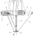
Fig. 2 is a schematic perspective view of the present invention.
Fig. 3 is a front view of the present invention.
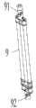
Fig. 4 is the sketch map of center rotary part.
Fig. 5 is the sketch map of handgrip installation component.
The specific embodiment
Shown in Fig. 1 to 5; Robot of the present invention; Comprise at least three first drive units 2 that are fixed on the level of pedestal 1 bottom; 1 of this pedestal is fixed on the frame 100, and the rotating shaft of each first drive unit 2 is fixed with rocking arm 3 respectively, can drive rocking arm 3 during the rotating shaft rotation and swing at perpendicular around the axis of its rotating shaft; Each rocking arm 3 is connected with the upper end of connecting rod 5 through oscillating bearing 4 away from an end of rotating shaft, and the lower end of all connecting rods 5 is connected with the handgrip installation component 7 that is used to install the handgrip (not shown) jointly through oscillating bearing 6.During work; Control system (like PLC control system) is according to the demand of concrete carrying, arrangement or assembly working; Give an order to each first drive unit 2, make the rotating shaft driving rocking arm 3 of first drive unit 2 do the swing of corresponding amplitude, thereby make rocking arm 3 drive link 5 drive handgrip installation components 7 in the vertical direction motion; Because the amplitude of fluctuation of each rocking arm 3 is different; Also can order about connecting rod 5 and drive 7 horizontal movements of handgrip installation component, make the handgrip (not shown) that is installed on the handgrip installation component 7 transport limit in each locus in its working range, grasp station material or product extracting; Then with movement of objects and be placed into preposition (in packing box), realize carrying, arrangement, or the work such as assembling of material or product.
Like Fig. 2, shown in Figure 3, described first drive unit 2 is servomotor or rotary cylinder, and described rocking arm 3 is fixed in the rotating shaft of first drive unit 2 through the planetary gear reductor.
Like Fig. 2, shown in Figure 3; Be fixed with its rotating shaft second drive unit 8 down on the described pedestal 1; This second drive unit 8 can be servomotor or rotary cylinder etc., but the top of the center rotary part 9 of an axial stretching be connected with the rotating shaft of second drive unit 8 through first shaft coupling 91, and can swing; Described first shaft coupling 91 is fixed in the rotating shaft of second drive unit 8 through the planetary gear reductor; The bottom of center rotary part 9 then is connected with the rotating disk of whirligig on being fixed on handgrip installation component 7 through second shaft coupling 92 and can swings, and described first shaft coupling 91 and second shaft coupling 92 all can be oscillating bearing, and described handgrip then is installed on the rotating disk of whirligig 71; Can be when the rotating shaft of second drive unit 8 is rotated through the dial rotation of center rotary part 9 driven rotary devices 71; Rotate thereby drive the handgrip (not shown), make the handgrip can be as required, before grasping material or product; The rotation handgrip is to grasp material or product better; The material or the product that perhaps will grasp when handgrip, be placed into the target location before, through rotating handgrip material or product are turned to the angle that needs.
Like Fig. 1, shown in Figure 2; Described pedestal 1 is fixed on the frame 100, and frame 100 is provided with vision system, when the material on the feeding web 10 that is positioned at pedestal 1 below or product run to the visual response scope of vision system with feeding web 10; Vision system can send to the control system with the information that receives; And change into instruction through the control system, and make 2 work of first drive unit, to drive handgrip different colours or dissimilar raw material or products (like parts) are classified; And can be according to real needs; Send instruction to drive the handgrip rotation to second drive unit 8, product at random on the feeding web 10 or material put neatly, perhaps according to demand with optional position pendulum in the working range of robot of material or product, assembling etc.; Described vision system is a prior art, no longer its structure and operation principle is given unnecessary details here.
As shown in Figure 2, described first drive unit 2 evenly distributes around the axis of the rotating shaft of second drive unit 8.
Claims (7)
1. robot; It is characterized in that: comprise at least three first drive units (2) that are fixed on the level of pedestal (1) bottom; The rotating shaft of each first drive unit (2) is fixed with rocking arm (3) respectively; Can drive rocking arm (3) during the rotating shaft rotation swings at perpendicular around the axis of its rotating shaft; Each rocking arm (3) is connected with the upper end of connecting rod (5) through oscillating bearing (4) away from an end of rotating shaft, and the lower end of all connecting rods (5) is connected with the handgrip installation component (7) that is used to install handgrip jointly through oscillating bearing (6).
2. robot according to claim 1 is characterized in that: described first drive unit (2) is servomotor or rotary cylinder, and described rocking arm (3) is fixed in the rotating shaft of first drive unit (2) through the planetary gear reductor.
3. robot according to claim 1; It is characterized in that: be fixed with its rotating shaft second drive unit (8) down on the described pedestal (1); But the top of the center rotary part (9) of an axial stretching is connected with the rotating shaft of second drive unit (8) through first shaft coupling (91) and can swings; The bottom of center rotary part (9) then is connected with the rotating disk of whirligig on being fixed on handgrip installation component (7) through second shaft coupling (92) and can swings; Described handgrip then is installed on the rotating disk of whirligig (71), can be through the dial rotation of center rotary part (9) driven rotary device (71) when the rotating shaft of second drive unit (8) is rotated.
4. according to claim 1 or 3 described robots; It is characterized in that: described pedestal (1) is fixed on the frame (100); Frame (100) is provided with vision system; When material on the feeding web (10) below being positioned at pedestal (1) or product run to the visual response scope of vision system with feeding web (10); Vision system can send to the control system with the information that receives, and changes into instruction through the control system, makes the work of first drive unit (2) or second drive unit (8).
5. robot according to claim 3 is characterized in that: described first drive unit (2) evenly distributes around the axis of the rotating shaft of second drive unit (8).
6. robot according to claim 3 is characterized in that: described second drive unit (8) is servomotor or rotary cylinder.
7. robot according to claim 1 is characterized in that: described first shaft coupling (91) is fixed in the rotating shaft of second drive unit (8) through the planetary gear reductor.
Priority Applications (1)
| Application Number | Priority Date | Filing Date | Title |
|---|---|---|---|
| CN2012103614576A CN102837308A (en) | 2012-09-26 | 2012-09-26 | Robot |
Applications Claiming Priority (1)
| Application Number | Priority Date | Filing Date | Title |
|---|---|---|---|
| CN2012103614576A CN102837308A (en) | 2012-09-26 | 2012-09-26 | Robot |
Publications (1)
| Publication Number | Publication Date |
|---|---|
| CN102837308A true CN102837308A (en) | 2012-12-26 |
Family
ID=47365166
Family Applications (1)
| Application Number | Title | Priority Date | Filing Date |
|---|---|---|---|
| CN2012103614576A Pending CN102837308A (en) | 2012-09-26 | 2012-09-26 | Robot |
Country Status (1)
| Country | Link |
|---|---|
| CN (1) | CN102837308A (en) |
Cited By (14)
| Publication number | Priority date | Publication date | Assignee | Title |
|---|---|---|---|---|
| CN103350417A (en) * | 2013-07-25 | 2013-10-16 | 天津大学 | Parallel mechanism capable of realizing three-dimensional translational motion and two-dimensional rotation |
| CN103802102A (en) * | 2014-02-14 | 2014-05-21 | 青岛汇智机器人有限公司 | Large telescopic double-cross joint rotation shaft of parallel robot |
| CN103802094A (en) * | 2014-02-14 | 2014-05-21 | 青岛汇智机器人有限公司 | Parallel robot |
| CN103895004A (en) * | 2014-04-04 | 2014-07-02 | 浙江钱江摩托股份有限公司 | Center shaft structure of delta robot |
| CN104139388A (en) * | 2014-07-30 | 2014-11-12 | 华南理工大学 | Delta parallel-connection mechanical hand for teaching |
| CN104526681A (en) * | 2014-12-25 | 2015-04-22 | 东莞理工学院 | Parallel mechanical hand |
| CN105563457A (en) * | 2014-10-10 | 2016-05-11 | 上海沃迪自动化装备股份有限公司 | Intermediate shaft mechanism for high-speed parallel robot |
| CN106217351A (en) * | 2016-08-04 | 2016-12-14 | 珠海格力智能装备有限公司 | Fixing seat, fixing holder assembly and parallel robot |
| CN106625607A (en) * | 2017-01-20 | 2017-05-10 | 常州大学 | Parallel grabbing robot at few degrees of freedom and with temperature recognition function |
| CN107827061A (en) * | 2017-12-04 | 2018-03-23 | 广州雍远溯智能装备科技有限公司 | A kind of feeding manipulator of chemical product automation and intelligent positioning crawl |
| CN107972017A (en) * | 2017-12-29 | 2018-05-01 | 勃肯特(天津)机器人技术有限公司 | Six axis serial-parallel mirror robots |
| CN108858180A (en) * | 2017-05-10 | 2018-11-23 | 大族激光科技产业集团股份有限公司 | Central shaft transmission device, parallel robot |
| CN110404820A (en) * | 2019-07-22 | 2019-11-05 | 潍坊学院 | A kind of parallel connection type connecting rod robotic arm apparatus of earphone speaker shell sorting |
| CN111546324A (en) * | 2019-02-08 | 2020-08-18 | 发那科株式会社 | Robot calibration method and robot calibration device |
Citations (8)
| Publication number | Priority date | Publication date | Assignee | Title |
|---|---|---|---|---|
| CN1785607A (en) * | 2005-10-28 | 2006-06-14 | 天津大学 | Space tritranslation parallel connection mechanism containing steel wire parallelogram fork chain structure |
| CN200988220Y (en) * | 2006-03-23 | 2007-12-12 | 哈尔滨工业大学深圳研究生院 | Parallel robot mechanism for realizing two dimension moving and rotation |
| CN101804631A (en) * | 2009-02-13 | 2010-08-18 | 发那科株式会社 | The parallel robot that possesses the wrist portion of 3DOF |
| CN101913146A (en) * | 2010-08-05 | 2010-12-15 | 安徽工业大学 | Concurrent parallelogram-containing three-translational freedom robot mechanism |
| US20110097184A1 (en) * | 2009-10-26 | 2011-04-28 | Fanuc Ltd | Parallel link robot |
| US20110100145A1 (en) * | 2009-11-05 | 2011-05-05 | Hong Fu Jin Precision Industry (Shenzhen) Co., Ltd. | Rotation mechanism and robot using the same |
| CN102059696A (en) * | 2009-11-18 | 2011-05-18 | 鸿富锦精密工业(深圳)有限公司 | Parallel mechanism |
| CN202825825U (en) * | 2012-09-26 | 2013-03-27 | 广州达意隆包装机械股份有限公司 | Robot |
-
2012
- 2012-09-26 CN CN2012103614576A patent/CN102837308A/en active Pending
Patent Citations (8)
| Publication number | Priority date | Publication date | Assignee | Title |
|---|---|---|---|---|
| CN1785607A (en) * | 2005-10-28 | 2006-06-14 | 天津大学 | Space tritranslation parallel connection mechanism containing steel wire parallelogram fork chain structure |
| CN200988220Y (en) * | 2006-03-23 | 2007-12-12 | 哈尔滨工业大学深圳研究生院 | Parallel robot mechanism for realizing two dimension moving and rotation |
| CN101804631A (en) * | 2009-02-13 | 2010-08-18 | 发那科株式会社 | The parallel robot that possesses the wrist portion of 3DOF |
| US20110097184A1 (en) * | 2009-10-26 | 2011-04-28 | Fanuc Ltd | Parallel link robot |
| US20110100145A1 (en) * | 2009-11-05 | 2011-05-05 | Hong Fu Jin Precision Industry (Shenzhen) Co., Ltd. | Rotation mechanism and robot using the same |
| CN102059696A (en) * | 2009-11-18 | 2011-05-18 | 鸿富锦精密工业(深圳)有限公司 | Parallel mechanism |
| CN101913146A (en) * | 2010-08-05 | 2010-12-15 | 安徽工业大学 | Concurrent parallelogram-containing three-translational freedom robot mechanism |
| CN202825825U (en) * | 2012-09-26 | 2013-03-27 | 广州达意隆包装机械股份有限公司 | Robot |
Cited By (18)
| Publication number | Priority date | Publication date | Assignee | Title |
|---|---|---|---|---|
| CN103350417A (en) * | 2013-07-25 | 2013-10-16 | 天津大学 | Parallel mechanism capable of realizing three-dimensional translational motion and two-dimensional rotation |
| CN103350417B (en) * | 2013-07-25 | 2015-03-04 | 天津大学 | Parallel mechanism capable of realizing three-dimensional translational motion and two-dimensional rotation |
| CN103802102A (en) * | 2014-02-14 | 2014-05-21 | 青岛汇智机器人有限公司 | Large telescopic double-cross joint rotation shaft of parallel robot |
| CN103802094A (en) * | 2014-02-14 | 2014-05-21 | 青岛汇智机器人有限公司 | Parallel robot |
| CN103895004A (en) * | 2014-04-04 | 2014-07-02 | 浙江钱江摩托股份有限公司 | Center shaft structure of delta robot |
| CN103895004B (en) * | 2014-04-04 | 2016-08-17 | 浙江钱江摩托股份有限公司 | A kind of middle shaft structure of delta robot |
| CN104139388A (en) * | 2014-07-30 | 2014-11-12 | 华南理工大学 | Delta parallel-connection mechanical hand for teaching |
| CN105563457A (en) * | 2014-10-10 | 2016-05-11 | 上海沃迪自动化装备股份有限公司 | Intermediate shaft mechanism for high-speed parallel robot |
| CN105563457B (en) * | 2014-10-10 | 2018-10-26 | 上海沃迪自动化装备股份有限公司 | A kind of shaft mechanism for high speed parallel robot |
| CN104526681B (en) * | 2014-12-25 | 2016-05-04 | 东莞理工学院 | Parallel manipulator |
| CN104526681A (en) * | 2014-12-25 | 2015-04-22 | 东莞理工学院 | Parallel mechanical hand |
| CN106217351A (en) * | 2016-08-04 | 2016-12-14 | 珠海格力智能装备有限公司 | Fixing seat, fixing holder assembly and parallel robot |
| CN106625607A (en) * | 2017-01-20 | 2017-05-10 | 常州大学 | Parallel grabbing robot at few degrees of freedom and with temperature recognition function |
| CN108858180A (en) * | 2017-05-10 | 2018-11-23 | 大族激光科技产业集团股份有限公司 | Central shaft transmission device, parallel robot |
| CN107827061A (en) * | 2017-12-04 | 2018-03-23 | 广州雍远溯智能装备科技有限公司 | A kind of feeding manipulator of chemical product automation and intelligent positioning crawl |
| CN107972017A (en) * | 2017-12-29 | 2018-05-01 | 勃肯特(天津)机器人技术有限公司 | Six axis serial-parallel mirror robots |
| CN111546324A (en) * | 2019-02-08 | 2020-08-18 | 发那科株式会社 | Robot calibration method and robot calibration device |
| CN110404820A (en) * | 2019-07-22 | 2019-11-05 | 潍坊学院 | A kind of parallel connection type connecting rod robotic arm apparatus of earphone speaker shell sorting |
Similar Documents
| Publication | Publication Date | Title |
|---|---|---|
| CN102837308A (en) | Robot | |
| JP6318264B2 (en) | Robot applying the principle of parallelogram | |
| CN202169229U (en) | Industrial spraying robot | |
| CN204366948U (en) | Articulated type series connection robot palletizer | |
| CN103010764B (en) | One parallel bar stacking machine robot | |
| CN103737207A (en) | Parallel-serial welding robot mechanism with six degrees of freedom | |
| CN103706517A (en) | Six-axis linkage dispensing machine | |
| CN105563468B (en) | A kind of parallel manipulator of cam control | |
| CN203919049U (en) | A kind of novel pneumatic manipulator | |
| CN203635427U (en) | Six-axis linkage dispensing machine | |
| CN103737577A (en) | Six-freedom-degree industrial robot with ball screw pair transmission | |
| CN205734889U (en) | A kind of Three Degree Of Freedom high-speed industrial parallel robot | |
| CN104029201A (en) | SCARA (selective compliance assembly robot arm) robot special for welding operation | |
| CN103737582A (en) | High-precision advanced welding robot mechanism with six degrees of freedom | |
| CN107949459A (en) | Using the multiple working device of connecting rod operation device | |
| CN106041902A (en) | Four-freedom-degree ten-rod controllable mechanism type stacking robot | |
| CN202825825U (en) | Robot | |
| CN104786211B (en) | A kind of Six-DOF industrial robot containing ball screw assembly, | |
| CN105522568A (en) | Seven-shaft robot with transverse moving mechanism | |
| CN102699896A (en) | Material separating rotating mechanical hand | |
| CN205272016U (en) | Carousel manipulator is cut apart to cam structure | |
| CN104742124B (en) | A kind of double-rod double-shaft two-way parallel track robot | |
| CN205148316U (en) | Parallel robot | |
| CN204414095U (en) | Plane two-degree-of-freedorobot robot | |
| CN103274344B (en) | Filling action mechanism of filling machine |
Legal Events
| Date | Code | Title | Description |
|---|---|---|---|
| C06 | Publication | ||
| PB01 | Publication | ||
| C10 | Entry into substantive examination | ||
| SE01 | Entry into force of request for substantive examination | ||
| C02 | Deemed withdrawal of patent application after publication (patent law 2001) | ||
| WD01 | Invention patent application deemed withdrawn after publication |
Application publication date: 20121226 |