CN102789289A - Computer radiating system - Google Patents
Computer radiating system Download PDFInfo
- Publication number
- CN102789289A CN102789289A CN2011101248477A CN201110124847A CN102789289A CN 102789289 A CN102789289 A CN 102789289A CN 2011101248477 A CN2011101248477 A CN 2011101248477A CN 201110124847 A CN201110124847 A CN 201110124847A CN 102789289 A CN102789289 A CN 102789289A
- Authority
- CN
- China
- Prior art keywords
- power supply
- fan
- supply unit
- heating radiator
- heat dissipating
- Prior art date
- Legal status (The legal status is an assumption and is not a legal conclusion. Google has not performed a legal analysis and makes no representation as to the accuracy of the status listed.)
- Pending
Links
Images


Classifications
-
- G—PHYSICS
- G06—COMPUTING; CALCULATING OR COUNTING
- G06F—ELECTRIC DIGITAL DATA PROCESSING
- G06F1/00—Details not covered by groups G06F3/00 - G06F13/00 and G06F21/00
- G06F1/16—Constructional details or arrangements
- G06F1/20—Cooling means
-
- G—PHYSICS
- G06—COMPUTING; CALCULATING OR COUNTING
- G06F—ELECTRIC DIGITAL DATA PROCESSING
- G06F1/00—Details not covered by groups G06F3/00 - G06F13/00 and G06F21/00
- G06F1/26—Power supply means, e.g. regulation thereof
Abstract
A computer radiating system comprises a computer case, wherein the computer case comprises a rear board and a side board, a radiator is fixed on the side board and a power supply is installed on the rear board, the power supply is provided with a first fan; a bottom wall facing the radiator is installed in the power supply and is provided with a plurality of first ventilating holes; the heat emitted by the radiator flow into the power supply through the first ventilating holes and is discharged from the computer case through the first fan in the power supply.
Description
Technical field
The invention relates to a kind of cooling system, refer to a kind of cooling system that is applied in the computer especially.
Background technology
Along with development of technology, the running frequency of chips such as the central processing unit in the computer, video card chip constantly promotes, and its power is also increasing; Like the double-core central processing unit of current trend, generally all more than 100 watts, the power of video card chip is broken through 100 watts to its power especially already; The increase of these element power has directly caused the straight line of its thermal value to rise; On the other hand, the cabinet of installing these elements but develops towards the direction of miniaturization, under the influence of above-mentioned two kinds of factors; If the heat dispersion of cabinet is not good; Heat in the cabinet is continued to increase, and temperature rises, and finally causes computer stability decreases, deadlock even generation to burn serious consequences such as hardware.Common settling mode is that a plurality of radiator fans are installed in computer housing, but the cost that a plurality of fans can increase computer is installed, and can produce bigger noise.
Summary of the invention
In view of above content, be necessary to provide the Computerized heat dissipating system that a kind of cost is lower and noise is less.
A kind of Computerized heat dissipating system; Comprise a computer chassis, said computer chassis comprises a back plate and a side plate, has fixed a heating radiator on the said side plate; Installed a power supply unit on the plate of said back; Be provided with one first fan in the said power supply unit, said power supply unit is provided with a diapire towards said heating radiator, and said diapire is provided with some first air vents; The heat of said heat sink radiates gets in the said power supply unit through these first air vents, and discharges said computer chassis through first fan in the said power supply unit.
Compared to prior art, Computerized heat dissipating system of the present invention helps to get rid of the heat in the said computer chassis through the fan in the power supply unit, and cost is lower and noise that produce is less.
Description of drawings
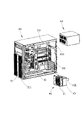
Fig. 1 is a three-dimensional exploded view of a preferred embodiments of Computerized heat dissipating system of the present invention.
Fig. 2 is the stereographic map of a power supply unit of the Computerized heat dissipating system of Fig. 1.
Fig. 3 is another stereographic map of the power supply unit of Fig. 2.
Fig. 4 is an assembly drawing of the Computerized heat dissipating system of Fig. 1.
The main element symbol description
| |
20 |
| |
21 |
| |
211 |
| |
22 |
| |
221 |
| |
23 |
| |
31 |
| The |
40 |
| |
41 |
| |
43 |
| |
431 |
| |
60 |
| Antetheca | 61 |
| The |
611 |
| Rear wall | 63 |
| Second air vent | 631 |
| Diapire | 65 |
| |
651 |
Following embodiment will combine above-mentioned accompanying drawing to further specify the present invention.
Embodiment
See also Fig. 1, a preferred embodiment of Computerized heat dissipating system of the present invention comprises a casing 20 and the assembly of fixing in this casing 20, and these assemblies comprise a heating radiator 31 and a power supply unit 60.
This casing 20 comprises a header board 21, one back plate 22 and side plate 23; Header board 21 is parallel to each other with back plate 22; Side plate 23 is connected between header board 21 and the back plate 22; And vertical with back plate 22 with header board 21, the bottom of header board 21 offered some ventilating openings 211, and a square opening 221 has been offered on the top of back plate 22.
One fan module 40 can be fixed on this heating radiator 31; This fan module 40 comprises one second fan 41 and a wind scooper 43; This second fan 41 is fixed on a side of this wind scooper 43; The opposite side of this wind scooper 43 is provided with a grab 431, and this wind scooper 43 can cover on the heating radiator 31, and this grab 431 can be buckled on the heating radiator 31 and wind scooper 43 and heating radiator 31 are fixed together.
See also Fig. 2 and Fig. 3, this power supply unit 60 is roughly a square block, the sizableness of its size and the opening 221 of casing 20; And can be installed in the casing 20 through opening 221; This power supply unit 60 comprises an antetheca 61, a rear wall 63 and a diapire 65, and this antetheca 61 is arranged in parallel with rear wall 63, and diapire 65 is connected between the lower limb of antetheca 61 and rear wall 63; And it is vertical with rear wall 63 with antetheca 61; Some first air vents 651 have been offered in the position of adjacent front wall 61 on the diapire 65, have offered some second air vents 631 on the rear wall 63, have offered some the 3rd air vents 611 on the antetheca 61; Near rear wall 63 places one first fan (figure does not show) is set in the power supply unit 60, second air vent 631 on this first fan and the rear wall 63 is relative.
See also Fig. 1 to Fig. 4; When assembling this Computerized heat dissipating system; Earlier the opening 221 of power supply unit 60 through casing 20 is installed in the casing 20; Make the rear wall 63 of power supply unit 60 roughly concordant with the back plate 22 of casing 20, in this position, the diapire 65 of power supply unit 60 is positioned at the top of heating radiator 31; Then the wind scooper 43 with fan module 40 covers on the heating radiator 31; The grab 431 of wind scooper 43 is buckled on the heating radiator 31; Thereby fan module 40 is fixed on the heating radiator 31; In this position, this second fan 41 between the header board 21 of heating radiator 31 and casing 20, second fan 41 also with header board 21 on ventilating opening 211 relative.
When this Computerized heat dissipating system work; Second fan 41 rotates and the air communication that drives casing 20 outsides is crossed the ventilating opening 211 of header board 21 and flowed in the casings 20; And flow through heating radiator 31 and take away the heat on the heating radiator 31; Then most of air-flow can flow in the power supply unit 60 through first air vent 651 on power supply unit 60 diapires 65, and first fan in the power supply unit 60 rotates and drives second air vent 631 and the outflow casing 20 of wall 63 after these air communication; The air-flow that has also can flow in the power supply unit 60 through the 3rd air vent 611 on the antetheca 61 of power supply unit 60, and first fan also can be crossed second air vent 631 with these air communication and discharge casing 20.
In above-mentioned Computerized heat dissipating system; Owing to offered the 3rd air hole 651 on the diapire 65 of the power supply unit 60 above being positioned at; Can make the air-flow of below in the casing 20 flow into power-supply radiator 60, and discharged, thereby be computer heat radiation effectively by first fan in the power supply unit 60.
Claims (7)
1. Computerized heat dissipating system; Comprise a computer chassis, said computer chassis comprises a back plate and a side plate, has fixed a heating radiator on the said side plate; Installed a power supply unit on the plate of said back; Be provided with one first fan in the said power supply unit, said power supply unit is provided with a diapire towards said heating radiator, it is characterized in that: said diapire is provided with some first air vents; The heat of said heat sink radiates gets in the said power supply unit through these first air vents, and discharges said computer chassis through first fan in the said power supply unit.
2. Computerized heat dissipating system as claimed in claim 1 is characterized in that: said computer chassis also comprise one with the parallel header board of said back plate, said header board has been offered some ventilating openings, these ventilating openings are relative with said heating radiator.
3. Computerized heat dissipating system as claimed in claim 2; It is characterized in that: a fan module is fixed on the said heating radiator; Said fan module comprises second fan between said heating radiator and said header board, and said second fan is relative with said ventilating opening.
4. Computerized heat dissipating system as claimed in claim 3; It is characterized in that: said fan module comprises a wind scooper; Said fan is fixed on a side of said wind scooper; The opposite side of said wind scooper is provided with a grab, and said wind-guiding cover cap is on said heating radiator, and said grab is buckled on the said heating radiator and said wind scooper and said heating radiator are fixed together.
5. Computerized heat dissipating system as claimed in claim 1 is characterized in that: an opening has been offered on the top of said back plate, and said power supply unit is fixed on said opening part.
6. Computerized heat dissipating system as claimed in claim 5; It is characterized in that: said power supply unit comprises an antetheca and a rear wall that is parallel to each other; Some the 3rd air vents have been offered on the said forearm; Offered some second air vents on the said rear wall, said rear wall is concordant with the back plate of said computer chassis, and said first fan is relative with said second air vent.
7. Computerized heat dissipating system as claimed in claim 6 is characterized in that: said diapire is vertically connected between the lower limb of said antetheca and rear wall.
Priority Applications (3)
| Application Number | Priority Date | Filing Date | Title |
|---|---|---|---|
| CN2011101248477A CN102789289A (en) | 2011-05-16 | 2011-05-16 | Computer radiating system |
| TW100117499A TW201248371A (en) | 2011-05-16 | 2011-05-18 | Heat dissipating system for computer |
| US13/296,528 US20120293957A1 (en) | 2011-05-16 | 2011-11-15 | Heat dissipating system for computer |
Applications Claiming Priority (1)
| Application Number | Priority Date | Filing Date | Title |
|---|---|---|---|
| CN2011101248477A CN102789289A (en) | 2011-05-16 | 2011-05-16 | Computer radiating system |
Publications (1)
| Publication Number | Publication Date |
|---|---|
| CN102789289A true CN102789289A (en) | 2012-11-21 |
Family
ID=47154704
Family Applications (1)
| Application Number | Title | Priority Date | Filing Date |
|---|---|---|---|
| CN2011101248477A Pending CN102789289A (en) | 2011-05-16 | 2011-05-16 | Computer radiating system |
Country Status (3)
| Country | Link |
|---|---|
| US (1) | US20120293957A1 (en) |
| CN (1) | CN102789289A (en) |
| TW (1) | TW201248371A (en) |
Cited By (1)
| Publication number | Priority date | Publication date | Assignee | Title |
|---|---|---|---|---|
| CN108541193A (en) * | 2018-05-31 | 2018-09-14 | 湖北省雄雄电子科技有限公司 | A kind of novel controller for electric vehicle |
Families Citing this family (3)
| Publication number | Priority date | Publication date | Assignee | Title |
|---|---|---|---|---|
| US20150185792A1 (en) * | 2013-12-26 | 2015-07-02 | Shih-Wun Li | DUAL-layer SYSTEM COMPUTER ENCLOSURE |
| US9745687B2 (en) * | 2014-11-12 | 2017-08-29 | Jay Kenneth Miller | Heating system for a machine with a light heat source |
| CN112230737A (en) * | 2020-11-24 | 2021-01-15 | 滨州学院 | Heat dissipation machine case for computer |
Family Cites Families (6)
| Publication number | Priority date | Publication date | Assignee | Title |
|---|---|---|---|---|
| US5559673A (en) * | 1994-09-01 | 1996-09-24 | Gagnon; Kevin M. | Dual filtered airflow systems for cooling computer components, with optimally placed air vents and switchboard control panel |
| US6034870A (en) * | 1999-01-27 | 2000-03-07 | Sun Microsystems, Inc. | Computer system having a highly efficient forced air cooling subsystem |
| KR200279417Y1 (en) * | 2002-03-11 | 2002-06-24 | 김휘철 | Cooling system for electric element of personal computer |
| TWM247898U (en) * | 2003-12-02 | 2004-10-21 | Hon Hai Prec Ind Co Ltd | Mounting apparatus for power supply |
| US7106586B2 (en) * | 2004-09-07 | 2006-09-12 | Shutlle Inc. | Computer heat dissipating system |
| US8047271B2 (en) * | 2007-12-20 | 2011-11-01 | Fu Zhun Precision Industry (Shen Zhen) Co., Ltd. | Heat dissipation device having a fan holder |
-
2011
- 2011-05-16 CN CN2011101248477A patent/CN102789289A/en active Pending
- 2011-05-18 TW TW100117499A patent/TW201248371A/en unknown
- 2011-11-15 US US13/296,528 patent/US20120293957A1/en not_active Abandoned
Cited By (1)
| Publication number | Priority date | Publication date | Assignee | Title |
|---|---|---|---|---|
| CN108541193A (en) * | 2018-05-31 | 2018-09-14 | 湖北省雄雄电子科技有限公司 | A kind of novel controller for electric vehicle |
Also Published As
| Publication number | Publication date |
|---|---|
| TW201248371A (en) | 2012-12-01 |
| US20120293957A1 (en) | 2012-11-22 |
Similar Documents
| Publication | Publication Date | Title |
|---|---|---|
| US8072753B2 (en) | Computer system | |
| US7522413B2 (en) | Heat dissipating system | |
| CN201138463Y (en) | Computer system with wind-guiding cowl | |
| CN101859168A (en) | Computer case | |
| CN201590029U (en) | Radiating system | |
| CN201600636U (en) | Shell of electronic device | |
| CN102298424A (en) | Computer shell | |
| CN103809711A (en) | Electronic device | |
| CN201226633Y (en) | Electronic device with radiating system | |
| CN102375476A (en) | Integrated computer | |
| CN102789289A (en) | Computer radiating system | |
| CN101221460A (en) | Computer cabinet | |
| CN103135706A (en) | Machine box of electronic device | |
| TW201528908A (en) | Computer case | |
| CN104765432A (en) | Server combination | |
| CN201097299Y (en) | Shielding plate and computer enclosure with shielding plate | |
| CN102375514A (en) | Electronic device | |
| CN102023688A (en) | Computer chassis with good heat dispersion performance | |
| CN102890548A (en) | All-in-one PC (Personal Computer) | |
| CN202583979U (en) | Host machine chassis of self-service terminal computer | |
| CN105988527A (en) | Electronic device shell | |
| CN208159095U (en) | A kind of subrack realizing front and back and radiating | |
| CN103901988B (en) | A kind of vehicle-mounted ruggedized computers of 1U | |
| CN203324916U (en) | Integrated computer | |
| CN202153328U (en) | Heat radiation structure of computer power supply |
Legal Events
| Date | Code | Title | Description |
|---|---|---|---|
| C06 | Publication | ||
| PB01 | Publication | ||
| C02 | Deemed withdrawal of patent application after publication (patent law 2001) | ||
| WD01 | Invention patent application deemed withdrawn after publication |
Application publication date: 20121121 |