CN102765624A - Folding device used for processing sheeting materials - Google Patents
Folding device used for processing sheeting materials Download PDFInfo
- Publication number
- CN102765624A CN102765624A CN2012102321652A CN201210232165A CN102765624A CN 102765624 A CN102765624 A CN 102765624A CN 2012102321652 A CN2012102321652 A CN 2012102321652A CN 201210232165 A CN201210232165 A CN 201210232165A CN 102765624 A CN102765624 A CN 102765624A
- Authority
- CN
- China
- Prior art keywords
- movable claw
- connecting rod
- folding device
- folding
- sheeting
- Prior art date
- Legal status (The legal status is an assumption and is not a legal conclusion. Google has not performed a legal analysis and makes no representation as to the accuracy of the status listed.)
- Pending
Links
Images


Classifications
-
- B—PERFORMING OPERATIONS; TRANSPORTING
- B65—CONVEYING; PACKING; STORING; HANDLING THIN OR FILAMENTARY MATERIAL
- B65H—HANDLING THIN OR FILAMENTARY MATERIAL, e.g. SHEETS, WEBS, CABLES
- B65H45/00—Folding thin material
- B65H45/12—Folding articles or webs with application of pressure to define or form crease lines
- B65H45/24—Interfolding sheets, e.g. cigarette or toilet papers
-
- B—PERFORMING OPERATIONS; TRANSPORTING
- B65—CONVEYING; PACKING; STORING; HANDLING THIN OR FILAMENTARY MATERIAL
- B65H—HANDLING THIN OR FILAMENTARY MATERIAL, e.g. SHEETS, WEBS, CABLES
- B65H45/00—Folding thin material
- B65H45/12—Folding articles or webs with application of pressure to define or form crease lines
- B65H45/28—Folding in combination with cutting
Abstract
A folding device used for processing sheeting materials mainly comprises a folding roller and a material pulling claw which is used for synchronously pulling the sheeting material absorbed on the surface of the folding roller in a vacuum manner out of the folding roller, wherein the material pulling claw consists of a connecting rod and a movable claw, one end of the connecting rod is connected with a swing mechanism, the rear part of the movable claw is arranged at the other end of the connecting rod by a pin shaft, the front part of the movable claw is positioned in a corresponding groove on the folding roller, and when the folding device blocks the material, the movable claw moves downwards by surrounding a pin shaft along with the extrusion of the blocked sheeting material. According to the folding device, as the structure that the connecting rod and the movable claw which is arranged on the connecting rod in a rotating manner by surrounding the pin shaft form the material pulling claw, when the folding device blocks the material, the movable claw automatically moves downwards along with the extrusion of the blocked sheeting material so as to be separated from the folding roller, so that the material pulling claw is prevented from being damaged; and the folding device disclosed by the invention has the advantages that the structure is reliable, and the service life of the material pulling claw is long.
Description
Technical field
The invention belongs to sheeting products processing machine tool field, particularly relate to a kind of folding device that is used to process such as netted sheetings of fabric such as paper for daily use, nonwoven fabrics.
Background technology
Existingly be used to process folding device such as netted sheetings of fabric such as paper for daily use, nonwoven fabrics; As shown in Figure 1; Mainly comprise folding roller and group material pawl that is used for vacuum suction is transferred to from folding roller in the lip-deep sheeting of folding roller synchronously; This group material pawl is as shown in Figure 2, is an all-in-one-piece rigid elongate body, and the front portion of wherein dialling the material pawl is positioned at the groove on the folding roller; Its rear portion is connected with a swinging gear; The synchronous high-speed swing with the high-speed operation of folding roller of described swinging gear is dialled synchronously reciprocally swinging of material pawl thereby drive, and makes to dial the material pawl and accomplish the periodicity action in the groove of folding roller is transferred to and returned to vacuum suction synchronously fast in the lip-deep sheeting of folding roller from folding roller.The folding device of this structure sheeting occurs through regular meeting in the course of the work and is placed in folding roller and the phenomenon of dialling in the material pawl, when occurring getting stuck, can hinder the normal swing of dialling the material pawl; Thereby cause the material pawl of dialling of the high-speed motion of rigidity the bending distortion to occur; Even the problem that fractures, therefore, in case the phenomenon that gets stuck occurs; Just must in time carry out manual work shuts down; Sheeting that cleaning fixes and group material pawl of changing the distortion of bending or fractureing, trouble-shooting causes the decline of production efficiency thus and increases the apparatus maintenance cost.
Summary of the invention
The objective of the invention is to above-mentioned existing problems and deficiency, a kind of reliable in structure is provided, dials the folding device that is used to process sheeting that the material pawl can the bending distortion.
Technical scheme of the present invention is achieved in that
The folding device that is used to process sheeting of the present invention; Mainly comprise folding roller and group material pawl that is used for vacuum suction is transferred to from folding roller in the sheeting on folding roller surface synchronously; It is characterized in that said group the material pawl form by connecting rod and movable claw; Wherein connecting rod one end is connected with a swinging gear, and in the connecting rod other end, the front portion of movable claw is positioned at the respective slot on the folding roller through a pin shaft device at the movable claw rear portion; And when phenomenon appearred getting stuck in said folding device, this movable claw can be with the extruding of the sheeting of institute's holding and is moved down around said bearing pin.
Wherein, The implementation that the structure that above-mentioned movable claw can move down around said bearing pin with the extruding of the sheeting of institute's holding when folding device occurs getting stuck phenomenon is formed is varied; Both can be that above-mentioned bearing pin is a screw rod; This screw rod through with being connected of nut with the movable claw holding on connecting rod; And two lateral surfaces of movable claw and/or two medial surfaces of connecting rod are friction face A; Through the cooperation between this friction face A, said movable claw and connecting rod form the annexation of plane clutch at this bearing pin place, also can be that above-mentioned bearing pin is one can the movable claw rear portion be articulated in the d-axis on the connecting rod; And the place, the place ahead that is positioned at this bearing pin position on the movable claw is provided with one can make movable claw under the extruding of the sheeting of holding, produce the supporting mechanism that moves down; This supporting mechanism is a screw rod, and this screw rod passes a sidewall and the overhead of connecting rod on a lateral surface of movable claw, and another lateral surface of movable claw and/or connecting rod and the corresponding medial surface of this lateral surface are friction face B; Through the cooperation between this friction face B; Said movable claw and connecting rod form the annexation of plane clutch at this screw rod place, can also be that above-mentioned bearing pin is one can the movable claw rear portion be articulated in the d-axis on the connecting rod, and the place, the place ahead that is positioned at this bearing pin position on the movable claw is provided with one and can makes movable claw under the extruding of the sheeting of holding, produce the elastic supporting mechanism that moves down.At this moment, described elastic supporting mechanism is also varied, both can be that above-mentioned elastic supporting mechanism comprises elasticity positioning bead that is installed on the connecting rod and the knock hole that is arranged at the movable claw sidepiece; The ball of said elasticity positioning bead peristome partly extend in the knock hole of movable claw sidepiece; Also can be that above-mentioned elastic supporting mechanism is a pressure spring, an end of this pressure spring be fixed on the connecting rod, and its other end overhead is in the movable claw bottom; Can also be that above-mentioned elastic supporting mechanism is a torque spring; The middle part of this torque spring is nested with to be fixed on the above-mentioned bearing pin, and its front portion is supported on the movable claw bottom, and its rear portion is fastened in the connecting rod bottom.
Be convenient swing and levelness of regulating movable claw; When particularly folding device is provided with many groups of material pawls; The movable claw that effectively guarantees each group material pawl all is positioned on the same horizon; Guarantee that manipulating of folding apparatus is more convenient and simple and reliable, above-mentioned connecting rod is provided with one and is used to regulate the adjusting screw(rod) of the movable claw anglec of rotation and levelness, and the bottom of this adjusting screw(rod) contacts with the top of movable claw.
For further guaranteeing the reliability of folding device of the present invention; Guarantee in the folding device in case the just auto-stop in time of phenomenon that occurs getting stuck; Make folding device can not receive further damage and remind the useless sheeting of operating personal cleaning holding in time; Above-mentioned folding device is provided with sensing device; This sensing device is positioned at the below of movable claw, when movable claw moves down under the extruding of the sheeting of holding, can make this sensing device produce the control signal that folding device is shut down automatically.
The present invention is owing to adopt connecting rod and can form the structure of dialling the material pawl around the movable claw that bearing pin is installed on the connecting rod rotationally; When the folding device normal operation; This movable claw is with connecting rod swing synchronously under the driving of swinging gear; Accomplish the sheeting that prize is adsorbed on the folding roller reliably and in time transfer to and the periodicity action that returns to rapidly in the folding roller groove, and when situation appears getting stuck in folding device, this movable claw can automatically move downward under the extruding of the sheeting of holding and be separated with folding roller; Avoid dialling the damage of material pawl, effectively enhance productivity and reduce the apparatus maintenance cost.Simultaneously; But the sensing device that below movable claw, is provided with can further guarantee the running of folding device automatic guidance folding device of the present invention; Effectively assurance equipment can not receive bigger damage, and folding device reliable in structure of the present invention, dials material pawl long service life.
Below in conjunction with accompanying drawing the present invention is further described.
Description of drawings
Fig. 1 is the existing structural representation that is used to process the folding device of sheeting.
Fig. 2 is the existing structural representation of dialling the material pawl that is used to process the folding device of sheeting.
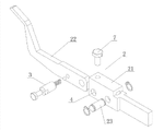
Structural representation when Fig. 3 normally moves for folding device of the present invention.
The structural representation of Fig. 4 when occurring getting stuck between of the present invention group of material pawl and the folding roller.
Fig. 5 is the main TV structure scheme drawing of of the present invention group of material pawl embodiment 1.
Fig. 6 is the cross-sectional view of Fig. 5 in the A-A direction.
Fig. 7 is the main TV structure scheme drawing of of the present invention group of material pawl embodiment 2.
Fig. 8 is the cross-sectional view of Fig. 7 in the B-B direction.
Fig. 9 is the decomposition texture scheme drawing of of the present invention group of material pawl embodiment 2.
Figure 10 is the cross-sectional view of of the present invention group of material pawl embodiment 3.
Figure 11 is the perspective view of of the present invention group of material pawl embodiment 4.
Figure 12 is the decomposition texture scheme drawing of of the present invention group of material pawl embodiment 4.
Figure 13 is the cross-sectional view of of the present invention group of material pawl embodiment 5.
The specific embodiment
Like Fig. 3-shown in Figure 13; The folding device that is used to process sheeting of the present invention; Mainly comprise folding roller 1 and group material pawl 2 that is used for vacuum suction is transferred to from folding roller 1 in the sheeting on folding roller 1 surface synchronously, said group of material pawl 2 is made up of connecting rod 21 and movable claw 22, and wherein connecting rod 21 1 ends are connected with a swinging gear 11; Movable claw 22 rear portions are installed on connecting rod 21 other ends through a bearing pin 23; The front portion of movable claw 22 is positioned at the respective slot on the folding roller 1, and when phenomenon appearred getting stuck in said folding device, these movable claw 22 meetings moved down around said bearing pin 23 with the extruding of the sheeting of institute's holding.Wherein, The implementation that the structure that above-mentioned movable claw can move down around said bearing pin with the extruding of the sheeting of institute's holding when folding device occurs getting stuck phenomenon is formed is varied; Both can be that above-mentioned bearing pin 23 is screw rod; This screw rod through with being connected of nut with movable claw 22 holdings on connecting rod 21; And two lateral surfaces of movable claw 22 and/or two medial surfaces of connecting rod 21 are friction face A81; Through the cooperation between this friction face A81, said movable claw 22 and connecting rod 21 form the annexation of plane clutch at these bearing pin 23 places, also can be that above-mentioned bearing pin 23 is one can movable claw 22 rear portions be articulated in the d-axis on the connecting rod 21; And the place, the place ahead that is positioned at these bearing pin 23 positions on the movable claw 22 is provided with one can make movable claw 22 under the extruding of the sheeting of holding, produce the supporting mechanism that moves down; This supporting mechanism is a screw rod 9, and this screw rod 9 passes a sidewall and the overhead of connecting rod 21 on a lateral surface of movable claw 22, and another lateral surface of movable claw 22 and/or connecting rod 21 are friction face B82 with the corresponding medial surface of this lateral surface; Through the cooperation between this friction face B82; Said movable claw 22 and connecting rod 21 form the annexation of plane clutch at these screw rod 9 places, can also be above-mentioned bearing pin 23 for by one have engaging and disengaging gear two minor axises form, wherein first minor axis of two minor axises is fixed on the connecting rod 21; Second minor axis is fixed in movable claw 22 rear portions; And connecting through an engaging and disengaging gear between first minor axis and second minor axis, can also be that above-mentioned bearing pin 23 is one can movable claw 22 rear portions be articulated in the d-axis on the connecting rod 21, and the place, the place ahead that is positioned at these bearing pin 23 positions on the movable claw 22 is provided with one and can makes movable claw 22 under the extruding of the sheeting of holding, produce the elastic supporting mechanism that moves down.At this moment; Described elastic supporting mechanism is also varied; Both can be that above-mentioned elastic supporting mechanism comprises elasticity positioning bead 3 that is installed on the connecting rod 21 and the knock hole 4 that is arranged at movable claw 22 sidepieces, the ball of said elasticity positioning bead 3 peristomes partly extend in the knock hole 4 of movable claw 22 sidepieces, also can be that above-mentioned elastic supporting mechanism is a pressure spring 5; One end of this pressure spring 5 is fixed on the connecting rod 21; Its other end overhead can also be that above-mentioned elastic supporting mechanism is a torque spring 6 in movable claw 22 bottoms, and the middle part of this torque spring 6 is nested with to be fixed on the above-mentioned bearing pin 23; Its front portion is supported on movable claw 22 bottoms, and its rear portion is fastened in connecting rod 21 bottoms.Wherein, friction face can be formed by the friction coatings that is arranged on the side.Be convenient swing and levelness of regulating movable claw; When particularly folding device is provided with many groups of material pawls; The movable claw that effectively guarantees each group material pawl all is positioned on the same horizon; Guarantee that manipulating of folding apparatus is more convenient and simple and reliable, above-mentioned connecting rod 21 is provided with one and is used to regulate the adjusting screw(rod) 7 of movable claw 22 anglecs of rotation and levelness, and the bottom of this adjusting screw(rod) 7 contacts with the top of movable claw 22.For further guaranteeing the reliability of folding device of the present invention; Guarantee in the folding device in case the just auto-stop in time of phenomenon that occurs getting stuck; Make folding device can not receive further damage and remind the useless sheeting of operating personal cleaning holding in time; Above-mentioned folding device is provided with sensing device 10; This sensing device 10 is positioned at the below of movable claw 22, when movable claw 22 moves down under the extruding of the sheeting of holding, can make this sensing device 10 produce the control signal that folding device is shut down automatically.And said sensing device 10 is electromagnetic inductor or opto-electronic pickup or or travel switch.
The present invention describes through embodiment; But the present invention is not constituted restriction, with reference to description of the invention, other variations of the disclosed embodiments; Professional person as for this area expects that easily such variation should belong within the scope thereof of the present invention.
Claims (10)
1. folding device that is used to process sheeting; Group material pawl (2) that mainly comprises folding roller (1) and be used for vacuum suction is transferred to from folding roller (1) in the sheeting on folding roller (1) surface synchronously; It is characterized in that said group the material pawl (2) form by connecting rod (21) and movable claw (22); Wherein connecting rod (21) one ends are connected with a swinging gear (11); Movable claw (22) rear portion is installed on connecting rod (21) other end through a bearing pin (23); The front portion of movable claw (22) is positioned at the respective slot on the folding roller (1), and when phenomenon appearred getting stuck in said folding device, this movable claw (22) meeting moved down around said bearing pin (23) with the extruding of the sheeting of institute's holding.
2. folding device according to claim 1; It is characterized in that above-mentioned bearing pin (23) is a screw rod; This screw rod through with being connected of nut with movable claw (22) holding on connecting rod (21); And two medial surfaces of two lateral surfaces of movable claw (22) and/or connecting rod (21) are friction face A (81), and through the cooperation between this friction face A (81), said movable claw (22) and connecting rod (21) locate to form the annexation of plane clutch at this bearing pin (23).
3. folding device according to claim 1; It is characterized in that above-mentioned bearing pin (23) is one can movable claw (22) rear portion be articulated in the d-axis on the connecting rod (21), and the place, the place ahead that is positioned at this bearing pin (23) position on the movable claw (22) is provided with one and can makes movable claw (22) under the extruding of the sheeting of holding, produce the elastic supporting mechanism that moves down.
4. folding device according to claim 3; It is characterized in that above-mentioned elastic supporting mechanism comprises the elasticity positioning bead (3) that is installed on the connecting rod (21) and is arranged at the knock hole (4) of movable claw (22) sidepiece, the ball of said elasticity positioning bead (3) peristome partly extend in the knock hole (4) of movable claw (22) sidepiece.
5. folding device according to claim 3 is characterized in that above-mentioned elastic supporting mechanism is a pressure spring (5), and an end of this pressure spring (5) is fixed on the connecting rod (21), and its other end overhead is in movable claw (22) bottom.
6. folding device according to claim 3; It is characterized in that above-mentioned elastic supporting mechanism is a torque spring (6); The middle part of this torque spring (6) is nested with to be fixed on the above-mentioned bearing pin (23), and its front portion is supported on movable claw (22) bottom, and its rear portion is fastened in connecting rod (21) bottom.
7. folding device according to claim 1; It is characterized in that above-mentioned bearing pin (23) is one can movable claw (22) rear portion be articulated in the d-axis on the connecting rod (21); And the place, the place ahead that is positioned at this bearing pin (23) position on the movable claw (22) is provided with one can make movable claw (22) under the extruding of the sheeting of holding, produce the supporting mechanism that moves down; This supporting mechanism is a screw rod (9); This screw rod (9) passes a sidewall and the overhead of connecting rod (21) on a lateral surface of movable claw (22); And another lateral surface of movable claw (22) and/or connecting rod (21) are friction face B (82) with the corresponding medial surface of this lateral surface, and through the cooperation between this friction face B (82), said movable claw (22) and connecting rod (21) locate to form the annexation of plane clutch at this screw rod (9).
8. according to claim 1 or 2 or 3 or 4 or 5 or 6 or 7 described folding devices; It is characterized in that above-mentioned folding device is provided with sensing device (10); This sensing device (10) is positioned at the below of movable claw (22), when movable claw (22) moves down under the extruding of the sheeting of holding, can make this sensing device (10) produce the control signal that folding device is shut down automatically.
9. folding device according to claim 8 is characterized in that above-mentioned sensing device (10) is electromagnetic inductor or opto-electronic pickup or travel switch.
10. according to claim 1 or 2 or 3 or 4 or 5 or 6 or 7 described folding devices; It is characterized in that above-mentioned connecting rod (21) is provided with one and is used to regulate the adjusting screw(rod) (7) of movable claw (22) anglec of rotation and levelness, the bottom of this adjusting screw(rod) (7) contacts with the top of movable claw (22).
Priority Applications (1)
| Application Number | Priority Date | Filing Date | Title |
|---|---|---|---|
| CN2012102321652A CN102765624A (en) | 2012-07-06 | 2012-07-06 | Folding device used for processing sheeting materials |
Applications Claiming Priority (1)
| Application Number | Priority Date | Filing Date | Title |
|---|---|---|---|
| CN2012102321652A CN102765624A (en) | 2012-07-06 | 2012-07-06 | Folding device used for processing sheeting materials |
Publications (1)
| Publication Number | Publication Date |
|---|---|
| CN102765624A true CN102765624A (en) | 2012-11-07 |
Family
ID=47093245
Family Applications (1)
| Application Number | Title | Priority Date | Filing Date |
|---|---|---|---|
| CN2012102321652A Pending CN102765624A (en) | 2012-07-06 | 2012-07-06 | Folding device used for processing sheeting materials |
Country Status (1)
| Country | Link |
|---|---|
| CN (1) | CN102765624A (en) |
Cited By (4)
| Publication number | Priority date | Publication date | Assignee | Title |
|---|---|---|---|---|
| CN104870348A (en) * | 2012-12-24 | 2015-08-26 | Sca纸巾法国公司 | Stack of folded absorbent sheet products, use of the same in a dispenser, method and machine for manufacturing the same |
| CN105668308A (en) * | 2016-03-30 | 2016-06-15 | 湖州南浔石淙盛艳丝绸有限公司 | Cloth clamping device with tensioning effect for plaiting machine |
| CN105775869A (en) * | 2016-03-30 | 2016-07-20 | 湖州南浔石淙盛艳丝绸有限公司 | Cloth folding machine with tensioning function |
| CN106586662A (en) * | 2016-12-28 | 2017-04-26 | 杜艳霞 | Hygienic material gauze folding machine |
Citations (9)
| Publication number | Priority date | Publication date | Assignee | Title |
|---|---|---|---|---|
| JPH0753122A (en) * | 1993-08-11 | 1995-02-28 | Katsu Yoneyama | Multiple-fold web forming device |
| JPH07291527A (en) * | 1994-04-28 | 1995-11-07 | Ishizu Seisakusho:Kk | Device for manufacturing web laminated body |
| JPH07330215A (en) * | 1994-04-11 | 1995-12-19 | Ishizu Seisakusho:Kk | Manufacturing device for fixed-quantity web layered body |
| US5526672A (en) * | 1995-07-20 | 1996-06-18 | Interbold | Press brake backgage |
| JP2000351526A (en) * | 1999-06-10 | 2000-12-19 | Kawanoe Zoki Co Ltd | Web zigzag folding up device |
| JP2002096968A (en) * | 2000-09-20 | 2002-04-02 | Ishizu Seisakusho Co Ltd | Device for manufacturing stack of folding web |
| CN201777721U (en) * | 2010-08-26 | 2011-03-30 | 合肥特丽洁卫生材料有限公司 | Device for folding paper towels |
| CN102502328A (en) * | 2011-11-07 | 2012-06-20 | 全利机械股份有限公司 | Device for folding fiber products |
| CN202727397U (en) * | 2012-07-06 | 2013-02-13 | 陆德昌 | Folding device for processing sheet materials |
-
2012
- 2012-07-06 CN CN2012102321652A patent/CN102765624A/en active Pending
Patent Citations (9)
| Publication number | Priority date | Publication date | Assignee | Title |
|---|---|---|---|---|
| JPH0753122A (en) * | 1993-08-11 | 1995-02-28 | Katsu Yoneyama | Multiple-fold web forming device |
| JPH07330215A (en) * | 1994-04-11 | 1995-12-19 | Ishizu Seisakusho:Kk | Manufacturing device for fixed-quantity web layered body |
| JPH07291527A (en) * | 1994-04-28 | 1995-11-07 | Ishizu Seisakusho:Kk | Device for manufacturing web laminated body |
| US5526672A (en) * | 1995-07-20 | 1996-06-18 | Interbold | Press brake backgage |
| JP2000351526A (en) * | 1999-06-10 | 2000-12-19 | Kawanoe Zoki Co Ltd | Web zigzag folding up device |
| JP2002096968A (en) * | 2000-09-20 | 2002-04-02 | Ishizu Seisakusho Co Ltd | Device for manufacturing stack of folding web |
| CN201777721U (en) * | 2010-08-26 | 2011-03-30 | 合肥特丽洁卫生材料有限公司 | Device for folding paper towels |
| CN102502328A (en) * | 2011-11-07 | 2012-06-20 | 全利机械股份有限公司 | Device for folding fiber products |
| CN202727397U (en) * | 2012-07-06 | 2013-02-13 | 陆德昌 | Folding device for processing sheet materials |
Cited By (7)
| Publication number | Priority date | Publication date | Assignee | Title |
|---|---|---|---|---|
| CN104870348A (en) * | 2012-12-24 | 2015-08-26 | Sca纸巾法国公司 | Stack of folded absorbent sheet products, use of the same in a dispenser, method and machine for manufacturing the same |
| CN105668308A (en) * | 2016-03-30 | 2016-06-15 | 湖州南浔石淙盛艳丝绸有限公司 | Cloth clamping device with tensioning effect for plaiting machine |
| CN105775869A (en) * | 2016-03-30 | 2016-07-20 | 湖州南浔石淙盛艳丝绸有限公司 | Cloth folding machine with tensioning function |
| CN105775869B (en) * | 2016-03-30 | 2017-12-22 | 湖州南浔石淙盛艳丝绸有限公司 | Plaiter with tensioning function |
| CN105668308B (en) * | 2016-03-30 | 2018-05-22 | 湖州南浔石淙盛艳丝绸有限公司 | Plaiter card cloth device with tension effects |
| CN106586662A (en) * | 2016-12-28 | 2017-04-26 | 杜艳霞 | Hygienic material gauze folding machine |
| CN106586662B (en) * | 2016-12-28 | 2017-10-13 | 杜艳霞 | Hygienic material gauze folding machine |
Similar Documents
| Publication | Publication Date | Title |
|---|---|---|
| CN102765624A (en) | Folding device used for processing sheeting materials | |
| CN208131535U (en) | Slicer and its Wiping mechanism | |
| US20130312551A1 (en) | Lifting device for a packaging machine | |
| CN110238095A (en) | Slicer and its Wiping mechanism | |
| CN203973536U (en) | A kind of four axis robot devices | |
| CN202727397U (en) | Folding device for processing sheet materials | |
| CN202911267U (en) | Positioning scraping machine | |
| CN202239055U (en) | Automatic cleaning device for aluminum plate flattening machine | |
| CN105460681B (en) | Single dimension flexible material paving device | |
| EP2374599B1 (en) | Take-up machine for an extrusion line | |
| CN203782462U (en) | Desk type cutting machine | |
| CN103302768B (en) | Discharge mechanism clamping device | |
| CN203580231U (en) | Paper product bonding servo correction system for paper pack machine and cover making machine | |
| CN204734431U (en) | Vacuum cleaner | |
| CN108851355A (en) | A kind of industrial robot sole crawl positioning device | |
| CN203682706U (en) | Bidirectional deviation rectifying device | |
| CN210059972U (en) | Automatic feeding and discharging system of plate shearing machine for production of lift car handrails | |
| CN108526317B (en) | Flexible automatic bending die for customizing integral bathroom | |
| CN102530607B (en) | Pipe reeling machine | |
| CN204528810U (en) | One connects volume robot device automatically | |
| CN204606329U (en) | In film chartered plane, film unreels draw gear | |
| CN214938216U (en) | Novel flat knitting machine traction mechanism | |
| CN204896923U (en) | Automatic change blowing seat structure of rectifying | |
| CN108861717A (en) | A kind of processing of tatami rush is with from reel-off gear | |
| CN106315283B (en) | A kind of coordinated type mechanical finger plectrum device applied to manipulator |
Legal Events
| Date | Code | Title | Description |
|---|---|---|---|
| C06 | Publication | ||
| PB01 | Publication | ||
| C10 | Entry into substantive examination | ||
| SE01 | Entry into force of request for substantive examination | ||
| C02 | Deemed withdrawal of patent application after publication (patent law 2001) | ||
| WD01 | Invention patent application deemed withdrawn after publication |
Application publication date: 20121107 |