CN102764603A - Mixer for mixing at least two flowing components and application device - Google Patents
Mixer for mixing at least two flowing components and application device Download PDFInfo
- Publication number
- CN102764603A CN102764603A CN2012101275712A CN201210127571A CN102764603A CN 102764603 A CN102764603 A CN 102764603A CN 2012101275712 A CN2012101275712 A CN 2012101275712A CN 201210127571 A CN201210127571 A CN 201210127571A CN 102764603 A CN102764603 A CN 102764603A
- Authority
- CN
- China
- Prior art keywords
- blender
- chamber
- access road
- composition
- designed
- Prior art date
- Legal status (The legal status is an assumption and is not a legal conclusion. Google has not performed a legal analysis and makes no representation as to the accuracy of the status listed.)
- Pending
Links
- 230000009969 flowable effect Effects 0.000 claims abstract description 6
- 239000000203 mixture Substances 0.000 claims description 79
- 238000003860 storage Methods 0.000 claims description 24
- 238000013461 design Methods 0.000 claims description 5
- 238000010397 one-hybrid screening Methods 0.000 claims description 3
- 238000007789 sealing Methods 0.000 claims description 2
- 238000007599 discharging Methods 0.000 abstract 2
- 230000000149 penetrating effect Effects 0.000 abstract 2
- 230000002349 favourable effect Effects 0.000 description 7
- 238000010586 diagram Methods 0.000 description 4
- 230000003068 static effect Effects 0.000 description 4
- 230000032258 transport Effects 0.000 description 4
- 239000011230 binding agent Substances 0.000 description 3
- 238000006243 chemical reaction Methods 0.000 description 3
- 238000005520 cutting process Methods 0.000 description 3
- 238000000034 method Methods 0.000 description 3
- 230000002950 deficient Effects 0.000 description 2
- 238000009826 distribution Methods 0.000 description 2
- 238000005516 engineering process Methods 0.000 description 2
- 238000002347 injection Methods 0.000 description 2
- 239000007924 injection Substances 0.000 description 2
- 238000002955 isolation Methods 0.000 description 2
- 238000012423 maintenance Methods 0.000 description 2
- 238000005266 casting Methods 0.000 description 1
- 239000002131 composite material Substances 0.000 description 1
- 239000000470 constituent Substances 0.000 description 1
- 230000001419 dependent effect Effects 0.000 description 1
- 230000006866 deterioration Effects 0.000 description 1
- 238000001035 drying Methods 0.000 description 1
- 239000006260 foam Substances 0.000 description 1
- 230000008676 import Effects 0.000 description 1
- 238000004519 manufacturing process Methods 0.000 description 1
- 239000000463 material Substances 0.000 description 1
- 239000012528 membrane Substances 0.000 description 1
- 238000012986 modification Methods 0.000 description 1
- 230000004048 modification Effects 0.000 description 1
- 238000000465 moulding Methods 0.000 description 1
- 230000035515 penetration Effects 0.000 description 1
- 238000012545 processing Methods 0.000 description 1
- 238000000926 separation method Methods 0.000 description 1
- 229920001169 thermoplastic Polymers 0.000 description 1
- 239000004416 thermosoftening plastic Substances 0.000 description 1
Images


Classifications
-
- A—HUMAN NECESSITIES
- A61—MEDICAL OR VETERINARY SCIENCE; HYGIENE
- A61C—DENTISTRY; APPARATUS OR METHODS FOR ORAL OR DENTAL HYGIENE
- A61C9/00—Impression cups, i.e. impression trays; Impression methods
- A61C9/0026—Syringes or guns for injecting impression material; Mixing impression material for immediate use
-
- B—PERFORMING OPERATIONS; TRANSPORTING
- B01—PHYSICAL OR CHEMICAL PROCESSES OR APPARATUS IN GENERAL
- B01F—MIXING, e.g. DISSOLVING, EMULSIFYING OR DISPERSING
- B01F27/00—Mixers with rotary stirring devices in fixed receptacles; Kneaders
- B01F27/05—Stirrers
- B01F27/09—Stirrers characterised by the mounting of the stirrers with respect to the receptacle
- B01F27/092—Stirrers characterised by the mounting of the stirrers with respect to the receptacle occupying substantially the whole interior space of the receptacle
-
- B—PERFORMING OPERATIONS; TRANSPORTING
- B01—PHYSICAL OR CHEMICAL PROCESSES OR APPARATUS IN GENERAL
- B01F—MIXING, e.g. DISSOLVING, EMULSIFYING OR DISPERSING
- B01F33/00—Other mixers; Mixing plants; Combinations of mixers
- B01F33/50—Movable or transportable mixing devices or plants
- B01F33/501—Movable mixing devices, i.e. readily shifted or displaced from one place to another, e.g. portable during use
- B01F33/5011—Movable mixing devices, i.e. readily shifted or displaced from one place to another, e.g. portable during use portable during use, e.g. hand-held
- B01F33/50112—Movable mixing devices, i.e. readily shifted or displaced from one place to another, e.g. portable during use portable during use, e.g. hand-held of the syringe or cartridge type
-
- B—PERFORMING OPERATIONS; TRANSPORTING
- B01—PHYSICAL OR CHEMICAL PROCESSES OR APPARATUS IN GENERAL
- B01F—MIXING, e.g. DISSOLVING, EMULSIFYING OR DISPERSING
- B01F35/00—Accessories for mixers; Auxiliary operations or auxiliary devices; Parts or details of general application
- B01F35/50—Mixing receptacles
- B01F35/52—Receptacles with two or more compartments
- B01F35/522—Receptacles with two or more compartments comprising compartments keeping the materials to be mixed separated until the mixing is initiated
-
- B—PERFORMING OPERATIONS; TRANSPORTING
- B01—PHYSICAL OR CHEMICAL PROCESSES OR APPARATUS IN GENERAL
- B01F—MIXING, e.g. DISSOLVING, EMULSIFYING OR DISPERSING
- B01F35/00—Accessories for mixers; Auxiliary operations or auxiliary devices; Parts or details of general application
- B01F35/71—Feed mechanisms
- B01F35/713—Feed mechanisms comprising breaking packages or parts thereof, e.g. piercing or opening sealing elements between compartments or cartridges
- B01F35/7131—Breaking or perforating packages, containers or vials
-
- B—PERFORMING OPERATIONS; TRANSPORTING
- B01—PHYSICAL OR CHEMICAL PROCESSES OR APPARATUS IN GENERAL
- B01F—MIXING, e.g. DISSOLVING, EMULSIFYING OR DISPERSING
- B01F35/00—Accessories for mixers; Auxiliary operations or auxiliary devices; Parts or details of general application
- B01F35/71—Feed mechanisms
- B01F35/717—Feed mechanisms characterised by the means for feeding the components to the mixer
- B01F35/71795—Squeezing a flexible container
-
- B—PERFORMING OPERATIONS; TRANSPORTING
- B05—SPRAYING OR ATOMISING IN GENERAL; APPLYING FLUENT MATERIALS TO SURFACES, IN GENERAL
- B05C—APPARATUS FOR APPLYING FLUENT MATERIALS TO SURFACES, IN GENERAL
- B05C17/00—Hand tools or apparatus using hand held tools, for applying liquids or other fluent materials to, for spreading applied liquids or other fluent materials on, or for partially removing applied liquids or other fluent materials from, surfaces
- B05C17/005—Hand tools or apparatus using hand held tools, for applying liquids or other fluent materials to, for spreading applied liquids or other fluent materials on, or for partially removing applied liquids or other fluent materials from, surfaces for discharging material from a reservoir or container located in or on the hand tool through an outlet orifice by pressure without using surface contacting members like pads or brushes
- B05C17/00503—Details of the outlet element
- B05C17/00516—Shape or geometry of the outlet orifice or the outlet element
-
- B—PERFORMING OPERATIONS; TRANSPORTING
- B05—SPRAYING OR ATOMISING IN GENERAL; APPLYING FLUENT MATERIALS TO SURFACES, IN GENERAL
- B05C—APPARATUS FOR APPLYING FLUENT MATERIALS TO SURFACES, IN GENERAL
- B05C17/00—Hand tools or apparatus using hand held tools, for applying liquids or other fluent materials to, for spreading applied liquids or other fluent materials on, or for partially removing applied liquids or other fluent materials from, surfaces
- B05C17/005—Hand tools or apparatus using hand held tools, for applying liquids or other fluent materials to, for spreading applied liquids or other fluent materials on, or for partially removing applied liquids or other fluent materials from, surfaces for discharging material from a reservoir or container located in or on the hand tool through an outlet orifice by pressure without using surface contacting members like pads or brushes
- B05C17/00553—Hand tools or apparatus using hand held tools, for applying liquids or other fluent materials to, for spreading applied liquids or other fluent materials on, or for partially removing applied liquids or other fluent materials from, surfaces for discharging material from a reservoir or container located in or on the hand tool through an outlet orifice by pressure without using surface contacting members like pads or brushes with means allowing the stock of material to consist of at least two different components
-
- B—PERFORMING OPERATIONS; TRANSPORTING
- B01—PHYSICAL OR CHEMICAL PROCESSES OR APPARATUS IN GENERAL
- B01F—MIXING, e.g. DISSOLVING, EMULSIFYING OR DISPERSING
- B01F25/00—Flow mixers; Mixers for falling materials, e.g. solid particles
- B01F25/40—Static mixers
- B01F25/42—Static mixers in which the mixing is affected by moving the components jointly in changing directions, e.g. in tubes provided with baffles or obstructions
-
- B—PERFORMING OPERATIONS; TRANSPORTING
- B05—SPRAYING OR ATOMISING IN GENERAL; APPLYING FLUENT MATERIALS TO SURFACES, IN GENERAL
- B05C—APPARATUS FOR APPLYING FLUENT MATERIALS TO SURFACES, IN GENERAL
- B05C17/00—Hand tools or apparatus using hand held tools, for applying liquids or other fluent materials to, for spreading applied liquids or other fluent materials on, or for partially removing applied liquids or other fluent materials from, surfaces
- B05C17/005—Hand tools or apparatus using hand held tools, for applying liquids or other fluent materials to, for spreading applied liquids or other fluent materials on, or for partially removing applied liquids or other fluent materials from, surfaces for discharging material from a reservoir or container located in or on the hand tool through an outlet orifice by pressure without using surface contacting members like pads or brushes
- B05C17/00586—Means, generally located near the nozzle, for piercing or perforating the front part of a cartridge
Abstract
The mixer (2) has a mixer housing (3) which has an outlet opening (7) for the components, a mixing element arranged in the mixer housing for mixing the components, and two separate inlet channels (5,6) through which the components are introduced in the area of the mixing elements. One of the inlet channels is configured at its end as a penetrating element (51) for opening a flow connection between a reservoir (8) or a chamber (92) and the inlet channels. The penetrating element has two inflow surfaces for the components. Both the surfaces are inclined relative to each other. An independent claim is included for a discharging device for discharging the two flowable components.
Description
Technical field
The present invention relates to the blender and the distributing equipment that are used to mix at least two kinds of compositions that can flow according to the preamble of corresponding independent claims.
Background technology
The static state or the dynamic mixer that are used for mixing at least two kinds of compositions are used to the multiple technologies field, for example are used for mixing the system of two kinds of compositions, for example the binding agent of the foam of sealed composite thing, two kinds of compositions or two kinds of compositions; Perhaps also can be used for dental field, for example be used to mix impression materials.It is separated from one another up to use that individual composition must keep usually, and follow mixed so that solidify subsequently through chemical reaction.This blender generally is designed to single and uses, because in fact these blenders can not be cleaned again after solidifying or after any other reaction of these compositions.
This blender is the part of distributing equipment normally, and this distributing equipment comprises box or other chambeies that is used for corresponding composition.In use, individual composition is assigned with, moves to the blender from this chamber, in this blender, leaves this blender by intimate admixture and as the exit opening of homogeneous mixing block through blender via plunger or via drivable piston.There are many different designs about the chamber that is used for composition.These chambeies can be designed to for example rigid case, and this rigid case is inserted directly in the distributing equipment.In view of the above, this box for example can each all have the piston as the bottom, and this piston moves in box through exerting pressure, to distribute corresponding composition.Also known box has the design of very thin wall.These boxes are inserted in the supporting box of distributing equipment then, and exert pressure on these boxes through plunger or piston.Can collapse in supporting box in a minute timing by regulation thin-walled box in this respect.Be known that in addition be used for composition the chamber each all be designed to tubular bag, this tubular bag is inserted into then in the supporting box and by pressure and applies and be compressed so that use.
In general, be necessary to store the individual composition in the chamber that is stored in complete closed, to avoid undesired reaction, drying or any other deterioration with air or its composition.Usually it is desirable for the associating locking device that is used for chamber (wherein tubular bag or thin-walled box are with the chamber that acts on composition) especially distributes.Therefore widely used measure is, for example is that the respective chamber of box or tubular bag was pierced before using for the first time, makes and can distribute corresponding composition subsequently.
Known such system; In this system; Adapter is placed on the box or is placed on the maintenance seat of the tubular bag that comprises piercing device, wherein for said adapter two positions is set, promptly; Piercing device keeps a fastening position respectively by box or by bag, and this position is used for storage and transports; The second place, in this second place, piercing device penetrates in this box, pierces through this box and therefore discharges this composition so that distribute.
This disadvantage is that this adapter is the part of disposable system and therefore must be processed.Generally speaking, also need special locking device to avoid any undesired piercing through.
Other embodiments have the piercing device that directly is attached to the maintenance seat that is respectively applied for box or tubular bag.If this box or tubular bag are inserted into respectively and are exposed under the pressure, piercing through of this wall taken place so, this wall is pushed and is cut open thus towards this piercing device thus.This system always need not make this box or tubular bag undesirably not pierced through respectively in storage, very careful when transporting and handling reliably and generally.
Also known such system from DE-196 18 693 for example; In this system; Piercing device is set at the access road place of blender; These piercing devices are designed to the pipe end of angular cutouts for this purpose, and every termination is incorporated in the outlet in chamber in the time of above this blender is placed on, and pierce through the wall in this chamber thus.Yet contingent in this embodiment is that this wall that is pierced self is positioned at the entering opening front of access road and covers this inlet opening at least in part, influences the distribution of composition thus unfriendly.Through access road is penetrated into box or in tubular bag, can prevent above-mentioned situation alternatively to thrust the degree of depth greatly, still therefore can not distribute this composition fully from box or from tubular bag respectively, thereby cause uneconomic residual quantity.The objective of the invention is to the defective following this striving direction as far as possible and avoid listing in the prior art.
From this prior art, therefore the objective of the invention is to propose a kind of blender and distributing equipment of being used to mix at least two kinds of flowable compositions that does not have these defectives.Not in-problem, reliably store and transport strain for maybe, and should easily handle this system, and should avoid stoping composition to distribute as far as possible through piercing through wall.
Summary of the invention
The subject content of the present invention that satisfies these purposes is characterized by the characteristic of corresponding independent claims.
According to the present invention, therefore a kind of blender that is used to mix at least two kinds of flowable compositions is proposed, said blender has: mixer case, it has the exit opening that is used for said composition; Be arranged at least one hybrid element that is used to mix said composition in the said mixer case; At least two access roades independently; Said composition can be introduced in the zone of said blender through said access road independently of one another; Wherein, each access road is designed to the corresponding exit passageway sealing cooperation with storage container or chamber, and wherein; At least one access road is designed in its end that element is intended to be used for and the cooperation of said exit passageway as piercing through, and is used to open mobile connection the between said storage container or said chamber and this access road.The said element that pierces through comprises at least two inflow regions that are used for said composition, and wherein, said two inflow regions relative to each other tilt.
Be shaped at the access road place of blender owing to pierce through element, therefore be used for storing the chamber composition the chamber wall or seal only when this blender is connected to storage container (this is only just in time generation before using usually) can be pierced.Guarantee the storage and simple processing of the transporting of safety, safety by this measure.Also comprise at least two inflow regions that tilt each other owing to pierce through element, prevent effectively that therefore the import of this access road is pierced wall or film obstruction.Therefore possibly realize the accessible distribution of corresponding composition.
Whole inflow region sums of access road are advantageously greater than this access road area of section vertical with its longitudinal axis, because this composition can especially easily be distributed through this big total inflow region.
In order to make that having each access road that pierces through element can supply this composition process that flows, this access road preferably is designed to ducted body; Especially preferably, this access road is designed to cylindrical tube basically.
In order to allow to pierce through the wall or the seal in the chamber that is used for this composition with simple as far as possible mode, preferably this pierces through element and comprises at least one tip.
According to first preferred implementation, two inflow regions contact with each other at the bus place.
In another preferred embodiment, two inflow regions are separated from one another by beam.
This beam preferably vertically extends with the longitudinal axis of said access road.
Because this beam is represented special stable structure, if therefore this beam has at least one tip, this is favourable.
This blender can be designed to have the dynamic mixer of rotatable hybrid element, that is, this hybrid element rotation is to mix these compositions.Certainly this blender can also be designed to known in itself static mixer; Promptly; These one or more hybrid elements do not move; But the one-tenth shunting of the mixing of composition through a plurality of separation becomes part stream and these parts stream repeatedly combines to take place, at this mixed tensor only from these compositions that flows.
According to embodiment, exactly an access road in the blender has one and pierces through element; Other one or more access roades are designed to not have the element of piercing through.
In addition; The present invention proposes a kind of distributing equipment that is used to distribute at least two kinds of flowable compositions; This distributing equipment has storage container; Said storage container is used to receive a respective chamber that is used for every kind of composition, and wherein, said storage container has at least one exit passageway that is used for a kind of composition and has the blender that is used to mix said composition.Said blender is designed according to the present invention.
In one embodiment; Said storage container has shoulder portion; Said shoulder portion receives a respective end in each chamber; Wherein, Said at least one exit passageway is set at said shoulder portion place and gives prominence on the side of said shoulder portion away from said chamber as post, and wherein, disposing in said at least one exit passageway that the said said access road that pierces through element joins said shoulder portion to and being sized to of said blender makes each pierce through element in mode of operation, can to thrust to reach in the said chamber and thrust the degree of depth.
In order to allow with this chamber of soaring of mode as far as possible completely, said thrust internal range that the degree of depth accounts for said access road at the most 50%, preferably at the most 33%.
At least one parts (that is, piercing through the parts that element thrusts) are designed to tubular bag, and the wall energy of said tubular bag is enough to be pierced through by the said element that pierces through.Yet also possible is that this chamber is designed to the box that box, especially thin-walled maybe can collapse.Also possible is, this chamber has closing membrane or closed film, makes this pierce through element and does not pierce through the wall in this chamber but pierce through this enclosed point.
This distributing equipment preferably has at least one piston or at least one plunger, is used for distributing said composition from said chamber.
Be injection moulded moulding at mixer case and hybrid element, preferably under the situation by the thermoplastic casting, favourable in manufacture view right and wrong especially simple and cost savings.
Other favourable measures of the present invention and embodiment stem from dependent claims.
Description of drawings
Hereinafter reference implementation mode and accompanying drawing are come to describe in more detail the present invention.In sketch map (part is a sectional view), illustrated:
Fig. 1 is the perspective partial decomposing schematic representation according to the embodiment of distributing equipment of the present invention;
Fig. 2 is the sectional view of the embodiment of Fig. 1; And
Fig. 3 to Fig. 9 is the corresponding perspective diagram according to the access road of the embodiment of blender of the present invention.
The specific embodiment
Fig. 1 shows the perspective partial decomposing schematic representation according to the critical piece of the embodiment of distributing equipment of the present invention, and this distributing equipment representes and comprise the embodiment of representing with Reference numeral 2 generally according to blender of the present invention generally with Reference numeral 1.Fig. 2 has illustrated this embodiment with local longitudinal cross-section sketch map.This embodiment is designed to distribute or mix two kinds of compositions that can flow.It being understood that this distributing equipment 1 or blender 2 can also be designed to more than two kinds of compositions that can flow.
Each all is arranged in the chamber 91,92 to treat mixed composition, and these compositions are stored and transport in this chamber.Usually, known in itself whole modification all are suitable as the chamber 91,92 that is used for these compositions.Therefore, each all is designed to the stable box of standing chamber 91,92, and this box also keeps its profile when soaring.Aspect this, the box bottom can be formed by piston, and this piston is moved in this box with known in itself mode via plunger along the longitudinal direction, with this box that soars.Chamber 91,92 can also realize that this thin-walled box is inserted in known manner in the supporting box and for example and can collapses so that distribute by the thin-walled box.This collapses can be for example to work with the similar mode of bellows.Also possible is, chamber 91,92 is designed to tubular bag, and these tubular bag are compressed in supporting box so that distribute then.Whole combinations of these designs also possibly be used for chamber 91,92 certainly.
In the embodiment herein, first chamber 91 that is used for first composition is designed to tubular bag, and second chamber 92 that is used for second composition is designed to thin-walled box (in the meaning that can not collapse).
Distributing equipment 1 also comprises storage container 8, and this storage container is admitted two chambeies 91,92.In this embodiment, storage container 8 comprises supporting box 81 (not shown in Fig. 2), and the chamber that is designed to tubular bag 91 that is used for first composition is inserted into this supporting box.Because second chamber 92 is designed to rigid case, therefore do not need supporting box and can for example be inserted in the guide (not shown) of storage container 8.
In the embodiment of describing herein, the chamber 92 that is used for second composition is designed to box, and this box disposes and goes out oral pillar 921 as the exit passageway of second composition.This that for example is used to store and transport goes out oral pillar and disposes closing cap, and before the chamber that forms box 92 was inserted in the storage container 8, this closing cap was removed (for example, breaking).Then, this access road 6 that goes out the opening in the outstanding shoulder portion of passing with exit passageway 84 axially parallels 83 of oral pillar 921 and can receive blender 2.
Certainly also possible is, is arranged in the tubular bag like second constituent class.It being understood that in this case second exit passageway replaces this and goes out oral pillar 921 and be set at shoulder portion 83 places.
In order to distribute these compositions, distributing equipment 1 comprises piston or plunger 85, and this piston or plunger 85 only are being used for first composition of supporting box 81 shown in Fig. 1.It being understood that also this piston or plunger to be set with second chamber, 92 similar modes.Possible thus is that this piston is the parts in first chamber 91 or second chamber 92, for example is formed integral in the box that forms second chamber 92.This piston can also be formed integral in the supporting box 81.Then, these pistons move up according to diagram so that distribute these compositions, and this forward travel is by being caused by the plunger 85 of manual drives or mechanically driving.
In the situation of this dynamic mixer 2, as in the embodiment shown in this, this distributing equipment 1 comprises driver 11 (Fig. 2), and the hybrid element 4 that this driver is provided with blender 2 via axle 12 is so that its rotation.Axle 12 in two chambeies 91, extend through opening in the shoulder portion 83 between 92 up to this blender 2 and enter into this blender 2.
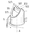
According to the present invention; At least one access road (is first access road 5 at this) is designed to pierce through element 51 in its end; Be intended to and exit passageway 84 cooperation, this pierces through element 51 as the mobile opening that is connected between first chamber 91 and this first access road 5.In Fig. 3, first access road 5 of the embodiment of Fig. 1 and Fig. 2 is illustrated with perspective view once more.This first access road 5 is designed to have the cylindrical tubes of inside diameter D substantially, and an end of this cylindrical tubes forms and pierces through element 51.According to the present invention, pierce through element 51 and have two inflow regions 511 and 512, these two inflow regions relative to each other tilt, and first composition can flow into first access road 5 from chamber 91 through these two inflow regions.
In the embodiment of describing herein; Two tips 521 and 522 are set in the wall of access road 5, and this wall with respect to longitudinal axis A extension and actual in extending below in most advanced and sophisticated 521 and 522 both sides according to diagram (Fig. 3) from tip 521 and 522 on both sides with cutting sth. askew.Most advanced and sophisticated 521 and 522 are provided with on diameter relative to one another.Therefore, the profile of wall all roughly forms U-shaped in all cases, and this U-shaped is dismembered its every end in most advanced and sophisticated 521 and 522 on the both sides at tip 521 and 522.Like what can find out best from Fig. 1, each is all crooked in the limb portion of two U-shapeds, makes the zone defined by this U-shaped camber all in all cases.
At this, the zone of being defined by a U-shaped and imaginary connecting line C (Fig. 3) most advanced and sophisticated 521, between 522 forms first inflow region 511; The zone of being defined by another U-shaped and imaginary line C forms second inflow region 512.Therefore, two inflow regions 511,512 relative to each other extend obliquely and contact with each other at imaginary connecting line C place.As mentioned, two inflow regions 511 and 512 each camber all, another if in the inflow region 511,512 one is designed to spill in two inflow regions 511,512 is designed to convex, and this has been proved to be favourable so.
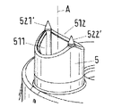
For the operation of distributing equipment 1 according to the present invention, first chamber 91 is inserted in the storage container 8 with the supporting cavity 81 and second chamber 92 together, makes respective end be received in (see figure 2) in the shoulder portion 83.If the closure member in this chamber 92 is set in advance, the closure member in this chamber 92 is removed in advance.This chamber 92 that is provided with out oral pillar 91 and is designed to box is maintained in the shoulder portion 83 via breech lock connector 922.Storage container 8 is closed and one or more plunger 85 or one or more piston are set at the end place away from shoulder portion 83 in chamber 91,92.
Blender 2 is placed to above the shoulder portion 83 at present; When doing like this, first access road 5 joins in the exit passageway 84 and second access road 6 joins to out in the oral pillar 921, wherein access road 5,6 be designed to make its each respectively with exit passageway 84 or with go out oral pillar 921 and cooperate hermetically.
Blender 2 is being placed under the situation in the shoulder portion 83, and the element 5 that pierces through of first access road 5 pierces through the wall in first chamber 91 and thrusts in the chamber 91 up to thrusting degree of depth T.
Substitute and possible to be, apply pressure on first chamber 91 by piston or plunger 85, the wall in chamber 91 is only thrust towards piercing through the element extruding and piercing through element by this.
Because two inflow regions 511 and 512 relative to each other inclinations and avoid such situation effectively: the wall that pierces through chamber 91 or pierce through film or film in the chamber 91 be used to open in or afterwards; The part of this wall, this film or this film is pushed to the front portion of first access road 5, makes basic first composition that stops 91 distribute from the chamber.
In this respect, if all inflow region 511,512 sums are greater than the area of section (being limited inside diameter D at this) of this access road 5, this is proved to be favourable so.Can realize this geometry especially, this is that out of plumb ground extends because at least one in the inflow region 511,512 tilts with respect to longitudinal axis A.
The geometry that pierces through element 51 makes that also access road 5 can be very little with respect to its length scaling, and it is little making the maximum that enters into chamber 91 thrust the degree of depth.Therefore possibly for example be provided with and thrust degree of depth T, make this T account for access road 5 internal range at the most 50%, preferably at the most 33%.In aforesaid cylindric access road 5, internal range is an inside diameter D.It is favourable that this spinule goes into degree of depth T, because possibly realize soar (this soars complete as far as possible) in chamber 91 thus.
To other the favourable embodiment that be respectively applied for first access road 5 or be used to pierce through element 51 be described with reference to figure 4 to Fig. 9 with the character of example at present.In this respect, with Fig. 3 in parts parts identical or that be equal on function be endowed identical Reference numeral.Each all shows the perspective diagram with the access road 5 that pierces through element 51 Fig. 4 to Fig. 9.
In embodiment according to Fig. 4, central tip 523 is set, this central tip is set on the longitudinal axis A of access road 5.Four posts 53 are from these central tip 523 extensions, with respect to longitudinal axis A inclination and downward according to sketch map, and the every end on the wall of access road 5 cuts off perpendicular to longitudinal axis.Thus, these ends preferably distribute on the periphery of this wall equidistantly.In addition, U-shaped otch 54 is set in the cylindrical wall.In order to help penetration process, four posts 53 can be designed to all reverse with respect to its respective central axes in all cases.In this embodiment, four inflow regions 511,512,513,514 all be set at two adjacent pillars 53 in all cases and another inflow region 54 of forming by the U-shaped otch between.
In embodiment according to Fig. 5; According to with reference to the similar mode of the embodiment of figure 3; Two tips 521 and 522 are set in the wall of access road 5; Against each other, and the wall of access road 5 extends with respect to longitudinal axis A from these two tips in both sides with cutting sth. askew on diameter at these two tips.Yet, compare sharper keen in these most advanced and sophisticated 521 and 522 embodiments of all being designed to Fig. 3.In addition, in the embodiment according to Fig. 5, two tips 521 are connected by beam 55 with 522, and this beam 55 extends perpendicular to longitudinal axis A.On this beam 55, be provided with and be positioned at another central tip 523 on the longitudinal axis A.In this embodiment, two inflow regions 511 and 512 separated from one another by beam 55.
Embodiment according to the embodiment of Fig. 6 and Fig. 3 is similar, but in the embodiment according to Fig. 6, two tips 521 are connected by beam 55 with 523, and this beam 55 is designed with concave curvature at this.According to accompanying drawing, the transverse end that beam 55 is located at the top is the direction convergent of axis A longitudinally, makes to form cutting edge 551 at this.
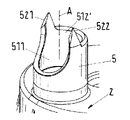
Embodiment according to Fig. 7 is also similar with the embodiment according to Fig. 3, but in the embodiment according to Fig. 7, on two diameters relative tip 521 ' with 522 ' each all be arranged in the isolation tip on the wall of access road 5.Two tips 521 ' and 522 ' each all be designed to cone point 521 ' and 522 '.
Fig. 8 show so that with another embodiment similar according to the embodiment of Fig. 3.Yet in the embodiment according to Fig. 8, the wall of access road 5 is only cut sth. askew with respect to longitudinal axis A at a side place of two tips 521 and 522, makes the inflow region 511 that forms U-shaped and arch at this.On most advanced and sophisticated 521 and 522 opposite side, the wall of access road 5 cuts off perpendicular to longitudinal axis A, makes relevant inflow region 512 ' be arranged to be approximately perpendicular to longitudinal axis A.Two tips 521 and 522 horizontal boundary are all cut sth. askew, and make each most advanced and sophisticated 521,522 be designed according to the mode similar with the tooth with general triangular profile.
Fig. 9 shows and the embodiment similar according to the embodiment of Fig. 7, and the tip 521 ' of two isolation and 522 ' all is set on the wall of access road 5, these most advanced and sophisticated each all design and have a tapered distal end according to cylindrical mode.The U-shaped otch 54 that forms an inflow region is set at and is positioned in the wall of access road 5 between two cylinders 521 ' and 522 ' on a side.On the opposite side between two cylinders 521 ' and 522 ', the wall of access road 5 has the zone that cuts off perpendicular to longitudinal axis A, makes that inflow region 512 is defined, and this inflow region extends perpendicular to this longitudinal axis A thus.In addition, lean-in corresponding general triangular wall section 56 of tiltedly extending is set at cylinder 521 ' and 522 ' on every side.Limit corresponding another inflow region 515 and 516 these two wall sections 56 at the place, both sides of two cylinders 521 ' and 522 '.
It being understood that the individual embodiment characteristic set forth with reference to figure 3 to Fig. 9 respective combination each other.
In the embodiment of the distributing equipment of describing herein 1, with reference to only a kind of applicable cases that is set in the chamber 91 of two kinds of compositions, via pierce through element 51 be used before this chamber 91 must be opened; Yet in the chamber that is designed to box 92, there is another composition, for example through breaking closure member or unscrew spiral cover and open this box.This applicable cases can for example realize under these circumstances: binding agent is set in first chamber 91 as first composition, and this chamber 91 is designed to tubular bag; Second chamber, 92 splendid attires are as the curing accelerator of second composition, and this curing accelerator mixes with binding agent to be used for accelerating curing.
Should be understood that; The present invention can also be applicable to such application certainly; In this was used, two kinds of compositions or more composition were set in the chamber that is designed to tubular bag or are set at it and export in this chamber of being closed by the seal of film, film or other type.In this case, each access road with the cooperation of this chamber of blender disposes in its respective end and pierces through element 51.
What it is also understood that is that the element that pierces through that is provided with at different access roades place can be designed identical or differently.
In addition, the present invention is applicable to also that certainly blender 2 is designed in this embodiment of static mixer.Be used for treating that one or more access roades of mixed composition can also dispose the element that pierces through of static mixer.
Claims (15)
1. blender that is used to mix at least two kinds of flowable compositions, said blender has: mixer case (3), this mixer case have the exit opening (7) that is used for said composition; Be arranged at least one hybrid element (4) that is used to mix said composition in the said mixer case (3); At least two access roades (5,6) independently, said composition can be introduced in the zone of said hybrid element (4) through said access road independently of one another, wherein, each access road (5; 6) be designed to cooperate, and wherein, at least one access road (5) is designed in its end as piercing through element (51) and is intended to be used for cooperate with said exit passageway (84) with a corresponding exit passageway (84, the 921) sealing of storage container (8) or chamber (91,92); Be used to open mobile connection the between said storage container (8) or said chamber (91,92) and this access road (5), it is characterized in that the said element (51) that pierces through comprises at least two inflow regions (511 that are used for said composition; 512,512 ', 513,514; 515,516,54), wherein; Said two inflow regions (511,512,512 ', 513; 514,515,516,54) relative to each other tilt.
2. blender according to claim 1, wherein, whole inflow regions (511,512 of access road (5); 512 ', 513,514; 515,516,54) summation is greater than this access road (5) and the vertical area of section of its longitudinal axis (A).
3. blender according to claim 1 and 2 wherein, has each access road (5) that pierces through element (51) and is designed to cylindrical tube substantially.
4. according to each described blender in the aforementioned claim, wherein, the said element (51) that pierces through comprises at least one tip (521,522,523,521 ', 522 ').
5. according to each described blender in the aforementioned claim, wherein, said two inflow regions (511,512,54,515,516) are located to contact with each other at bus (C).
6. according to each described blender in the claim 1 to 4, wherein, said two inflow regions (511,512 ') are separated from one another through beam (55).
7. blender according to claim 6, wherein, said beam (55) vertically extends with the longitudinal axis (A) of said access road (5).
8. according to the described blender in one of claim 6 or 7, wherein, said beam (55) has at least one tip (523).
9. according to each described blender in the aforementioned claim, said blender is designed to have the dynamic mixer of rotatable hybrid element (4).
10. according to each described blender in the aforementioned claim, wherein, exactly an access road (5) has the element of piercing through (51).
11. distributing equipment that is used to distribute at least two kinds of flowable compositions; Said distributing equipment has storage container (8), and said storage container is used to receive a respective chamber (91,92) that is used for every kind of composition; Wherein, Said storage container (8) has at least one exit passageway (84) that is used for one of said composition and has the blender (2) that is used to mix said composition, it is characterized in that said blender (2) is according to each design in the aforementioned claim.
12. distributing equipment according to claim 11; Wherein, Said storage container (8) has shoulder portion (83); A respective end in said shoulder portion each chamber of reception (91,92), wherein; Said at least one exit passageway (84) is set at that said shoulder portion (83) locates and gives prominence in said shoulder portion (83) away from said chamber (91 as post; 92) on the side, wherein, disposing in said at least one exit passageway (84) that the said said access road (5) that pierces through element (51) joins said shoulder portion to and being sized to of said blender (2) makes each pierce through element (51) in mode of operation, can to thrust to reach in the said chamber and thrust the degree of depth (T).
13. distributing equipment according to claim 12, wherein, said thrust internal range (D) that the degree of depth (T) accounts for said access road at the most 50%, preferably at the most 33%.
14. according to each described distributing equipment in the claim 11 to 13, wherein, at least one chamber (91) are designed to tubular bag, the wall energy of said tubular bag is enough to be pierced through by the said element (51) that pierces through.
15. according to each described distributing equipment in the claim 11 to 14, said distributing equipment has at least one piston (85) or has at least one plunger (85), is used for distributing said composition from said chamber.
Applications Claiming Priority (2)
| Application Number | Priority Date | Filing Date | Title |
|---|---|---|---|
| EP11164431.6 | 2011-05-02 | ||
| EP11164431 | 2011-05-02 |
Publications (1)
| Publication Number | Publication Date |
|---|---|
| CN102764603A true CN102764603A (en) | 2012-11-07 |
Family
ID=45757342
Family Applications (1)
| Application Number | Title | Priority Date | Filing Date |
|---|---|---|---|
| CN2012101275712A Pending CN102764603A (en) | 2011-05-02 | 2012-04-27 | Mixer for mixing at least two flowing components and application device |
Country Status (14)
| Country | Link |
|---|---|
| US (1) | US9149775B2 (en) |
| EP (1) | EP2520360B1 (en) |
| JP (1) | JP6029313B2 (en) |
| KR (1) | KR101924909B1 (en) |
| CN (1) | CN102764603A (en) |
| AU (1) | AU2012202426B2 (en) |
| BR (1) | BR102012009978B1 (en) |
| CA (1) | CA2770832C (en) |
| DK (1) | DK2520360T3 (en) |
| ES (1) | ES2503618T3 (en) |
| MX (1) | MX2012004836A (en) |
| PL (1) | PL2520360T3 (en) |
| RU (1) | RU2582397C2 (en) |
| TW (1) | TWI577408B (en) |
Cited By (2)
| Publication number | Priority date | Publication date | Assignee | Title |
|---|---|---|---|---|
| CN106714978A (en) * | 2014-07-09 | 2017-05-24 | 苏舍米克斯帕克有限公司 | Dispensing apparatus, dispensing system and method of dispensing |
| CN107073512A (en) * | 2014-09-23 | 2017-08-18 | Sika技术股份公司 | Coating unit for multi-component material |
Families Citing this family (12)
| Publication number | Priority date | Publication date | Assignee | Title |
|---|---|---|---|---|
| EP2468416A1 (en) * | 2010-12-24 | 2012-06-27 | Sika Technology AG | Application device for multi-pack products, cartridge set and packaging unit |
| CN103998148B (en) * | 2011-10-17 | 2019-12-31 | 苏舍米克斯帕克有限公司 | Cartridge, method for manufacturing such a cartridge and multi-component cartridge |
| KR101406068B1 (en) * | 2013-09-05 | 2014-06-11 | (주)디엑스엠 | Impression mixing tip |
| US9527106B2 (en) | 2013-10-31 | 2016-12-27 | Nordson Corporation | Applicator and method for dispensing a viscous fluid |
| EP3197607B1 (en) | 2014-09-23 | 2021-10-20 | Sika Technology AG | Head plate device, storage container device, cartridge arrangement, dispensing apparatus, and their usage |
| EP3031747B1 (en) * | 2014-12-11 | 2018-10-10 | Henkel IP & Holding GmbH | Dispensing pack comprising compressible foam/fibre inserts and method for varying the dispensing volume ratio of a dispensing pack |
| US9572555B1 (en) * | 2015-09-24 | 2017-02-21 | Ethicon, Inc. | Spray or drip tips having multiple outlet channels |
| AT522023B1 (en) * | 2019-01-14 | 2020-12-15 | Mayrpeter Johannes | Filling mandrel |
| DE102019101651A1 (en) * | 2019-01-23 | 2020-07-23 | 3lmed GmbH | Application system with improved seal |
| PL3936454T3 (en) | 2020-07-08 | 2023-03-13 | Soudal | Cartridge cap and cartridge assembly |
| CN113522156A (en) * | 2021-07-28 | 2021-10-22 | 苏州通五洲科技有限公司 | Closed putty material mixing equipment |
| WO2023154294A2 (en) * | 2022-02-09 | 2023-08-17 | Markesbery Blue Pearl LLC | Concurrent dispersion of liquid compositions |
Citations (4)
| Publication number | Priority date | Publication date | Assignee | Title |
|---|---|---|---|---|
| US20020066677A1 (en) * | 2000-12-01 | 2002-06-06 | Brett Moscovitz | Device for storing and dispensing a substance by mating with a container and associated methods |
| US7073686B2 (en) * | 2003-07-15 | 2006-07-11 | Hanell Edward G | Pouring spout |
| US20080023495A1 (en) * | 2006-07-28 | 2008-01-31 | Q.P. Corporation | Viscous liquid material dispensing gun |
| US20080251535A1 (en) * | 2007-04-16 | 2008-10-16 | Kettenbach Gmbh & Co. Kg | Container and method for opening a container |
Family Cites Families (27)
| Publication number | Priority date | Publication date | Assignee | Title |
|---|---|---|---|---|
| US2058905A (en) * | 1936-10-27 | Combined opener and spotjx for | ||
| US1550370A (en) * | 1922-09-01 | 1925-08-18 | Albert M Kruger | Grease gun |
| US2587683A (en) * | 1949-09-09 | 1952-03-04 | Robert E Barry | Disposable caulking gun |
| US4174868A (en) * | 1977-08-25 | 1979-11-20 | Nardo John M De | Apparatus for pneumatically applying material to an object |
| US5161715A (en) * | 1991-03-25 | 1992-11-10 | Giannuzzi Anthony C | Double-barreled epoxy injection gun |
| US5566859A (en) * | 1991-09-19 | 1996-10-22 | Willis; Charles M. | Foil piercing and clearing nozzle |
| NL9200318A (en) * | 1992-02-20 | 1993-09-16 | Wilhelmus Adrianus Theresia Ke | Apparatus for dispensing viscous material |
| DE4316807A1 (en) * | 1993-05-19 | 1994-11-24 | Friedhelm Schneider | Metering gun for tubular bags with highly viscous contents |
| DE4335970A1 (en) * | 1993-10-21 | 1995-04-27 | Hilti Ag | Foil bag pack with foil bag and bottom part |
| GB9401439D0 (en) * | 1994-01-26 | 1994-03-23 | Ciba Geigy Ag | Apparatus |
| RU2060806C1 (en) * | 1994-07-27 | 1996-05-27 | Акционерное общество открытого типа "Трансфер" | Mixer |
| DE19618693A1 (en) | 1996-05-09 | 1997-11-13 | Upat Max Langensiepen Kg | Cartridge for interchangeable twin component masses in foil bags |
| DE29923938U1 (en) * | 1998-10-14 | 2001-07-19 | Kettenbach Gmbh & Co Kg | Device for discharging a pasty two-component mixture |
| JP2000284450A (en) * | 1999-03-31 | 2000-10-13 | Fuji Photo Film Co Ltd | Processing agent dissolving device |
| US6210030B1 (en) * | 1999-06-15 | 2001-04-03 | Jean-Pierre Ibar | Method and apparatus to control viscosity of molten plastics prior to a molding operation |
| ATE273065T1 (en) * | 1999-11-12 | 2004-08-15 | Kettenbach Gmbh & Co Kg | DEVICE FOR MIXING TWO PASTY MASSES, IN PARTICULAR FOR MIXING A DENTAL IMPRESSION MATERIAL WITH A CATALYST MATERIAL |
| RU2245188C2 (en) * | 2000-01-31 | 2005-01-27 | Тетра Лаваль Холдингз Энд Файненс С.А. | Method and device for mixing fluid media |
| US8147122B2 (en) * | 2003-03-06 | 2012-04-03 | Dentsply International Inc. | Dispensing and mixing tip for reactive componets |
| US7390467B2 (en) * | 2003-05-02 | 2008-06-24 | Ecolab Inc. | Dispensing apparatus and method suitable for heterogeneous composition |
| DE10337789A1 (en) * | 2003-08-14 | 2005-09-15 | 3M Espe Ag | Single dose syringe for a multi-component material |
| DE102004003774A1 (en) * | 2004-01-23 | 2005-08-25 | Heraeus Kulzer Gmbh | Device for opening a tubular bag and its use |
| DE602006011772D1 (en) * | 2005-10-07 | 2010-03-04 | Sulzer Mixpac Ag | DYNAMIC MIXER |
| WO2007095768A1 (en) * | 2006-02-21 | 2007-08-30 | Medmix Systems Ag | Device for piercing film bags |
| JP5211499B2 (en) * | 2006-10-04 | 2013-06-12 | 横浜ゴム株式会社 | Packing jig for caulking gun for sealing material pack |
| RU2523995C2 (en) * | 2006-12-15 | 2014-07-27 | 3М Инновейтив Пропертиз Компани | Mixing and feeding of multicomponent hardenable materials via dispenser |
| US8376187B2 (en) * | 2007-03-19 | 2013-02-19 | Sulzer Mixpac Ag | Dispensing assembly having removably attachable accessories |
| WO2012055926A1 (en) * | 2010-10-26 | 2012-05-03 | Kettenbach Gmbh & Co. Kg | Double cartridge, mixer therefor and combination of double cartridge and mixer |
-
2012
- 2012-03-05 PL PL12158027T patent/PL2520360T3/en unknown
- 2012-03-05 DK DK12158027.8T patent/DK2520360T3/en active
- 2012-03-05 EP EP12158027.8A patent/EP2520360B1/en active Active
- 2012-03-05 ES ES12158027.8T patent/ES2503618T3/en active Active
- 2012-03-13 CA CA2770832A patent/CA2770832C/en active Active
- 2012-04-06 KR KR1020120036028A patent/KR101924909B1/en active IP Right Grant
- 2012-04-23 JP JP2012097242A patent/JP6029313B2/en active Active
- 2012-04-25 MX MX2012004836A patent/MX2012004836A/en active IP Right Grant
- 2012-04-27 RU RU2012117757/05A patent/RU2582397C2/en active
- 2012-04-27 CN CN2012101275712A patent/CN102764603A/en active Pending
- 2012-04-27 BR BR102012009978-0A patent/BR102012009978B1/en not_active IP Right Cessation
- 2012-04-27 AU AU2012202426A patent/AU2012202426B2/en not_active Ceased
- 2012-04-27 TW TW101115200A patent/TWI577408B/en not_active IP Right Cessation
- 2012-04-30 US US13/459,409 patent/US9149775B2/en active Active
Patent Citations (4)
| Publication number | Priority date | Publication date | Assignee | Title |
|---|---|---|---|---|
| US20020066677A1 (en) * | 2000-12-01 | 2002-06-06 | Brett Moscovitz | Device for storing and dispensing a substance by mating with a container and associated methods |
| US7073686B2 (en) * | 2003-07-15 | 2006-07-11 | Hanell Edward G | Pouring spout |
| US20080023495A1 (en) * | 2006-07-28 | 2008-01-31 | Q.P. Corporation | Viscous liquid material dispensing gun |
| US20080251535A1 (en) * | 2007-04-16 | 2008-10-16 | Kettenbach Gmbh & Co. Kg | Container and method for opening a container |
Cited By (3)
| Publication number | Priority date | Publication date | Assignee | Title |
|---|---|---|---|---|
| CN106714978A (en) * | 2014-07-09 | 2017-05-24 | 苏舍米克斯帕克有限公司 | Dispensing apparatus, dispensing system and method of dispensing |
| CN106714978B (en) * | 2014-07-09 | 2020-06-05 | 苏舍米克斯帕克有限公司 | Distribution equipment, distribution system and distribution method |
| CN107073512A (en) * | 2014-09-23 | 2017-08-18 | Sika技术股份公司 | Coating unit for multi-component material |
Also Published As
| Publication number | Publication date |
|---|---|
| ES2503618T3 (en) | 2014-10-07 |
| EP2520360A1 (en) | 2012-11-07 |
| TW201311308A (en) | 2013-03-16 |
| CA2770832C (en) | 2019-01-15 |
| KR101924909B1 (en) | 2018-12-04 |
| AU2012202426B2 (en) | 2014-06-26 |
| JP2012232294A (en) | 2012-11-29 |
| PL2520360T3 (en) | 2014-11-28 |
| MX2012004836A (en) | 2012-11-26 |
| US20120279988A1 (en) | 2012-11-08 |
| JP6029313B2 (en) | 2016-11-24 |
| TWI577408B (en) | 2017-04-11 |
| BR102012009978A2 (en) | 2013-06-18 |
| RU2012117757A (en) | 2013-11-10 |
| EP2520360B1 (en) | 2014-07-16 |
| US9149775B2 (en) | 2015-10-06 |
| RU2582397C2 (en) | 2016-04-27 |
| DK2520360T3 (en) | 2014-09-01 |
| CA2770832A1 (en) | 2012-11-02 |
| KR20120124023A (en) | 2012-11-12 |
| BR102012009978B1 (en) | 2020-09-24 |
Similar Documents
| Publication | Publication Date | Title |
|---|---|---|
| CN102764603A (en) | Mixer for mixing at least two flowing components and application device | |
| ES2222430T3 (en) | DISPENSER WITH DRILLING NEEDLE FOR MATERIALS TO MIX DURING DISTRIBUTION. | |
| DE19831791B4 (en) | Cartridge-like container for holding two substances that come into contact with each other only when in use | |
| CN103786957A (en) | Fluid dispensing assemblies and methods of dispensing fluids from containers | |
| JP6033683B2 (en) | Metering device for metering and releasing liquid formulations, method of operating the metering device, and use of the metering device | |
| CN101505860A (en) | Device and method for storing, mixing and dispensing components | |
| EP3621478B1 (en) | System for mixing two cosmetic products | |
| JPH0858852A (en) | Bilocular container | |
| EP2279786B1 (en) | Device and method for gassing a liquid | |
| JP2002537047A (en) | Mixing adapters and systems | |
| DE102015011170A1 (en) | Capsule for production of a liquid food, method of making a capsule for production of a liquid food, use of a capsule for production of a liquid food, system of capsule and device, and device for producing a liquid food | |
| EP2605858A1 (en) | Dispensing module and method for filling a dispensing module | |
| EP2847084B1 (en) | Closure cap | |
| EP2753289B1 (en) | Liquid container with predetermined break point | |
| EP3194300A1 (en) | Capsule and system for preparing a liquid food | |
| US20180229252A1 (en) | Device for mixing and dispensing a chemical substance formed from reactant liquid components | |
| JP3202068U (en) | Shaker container and shaker device using the same | |
| KR20120132321A (en) | Plastic container, long flow member and coating apparatus | |
| TWI574707B (en) | Syringe devices and syringe piston | |
| CN107455242A (en) | Rhizine fertilizing device | |
| CN202173587U (en) | Dust-proofing transfusion soft bag | |
| DE2729850B2 (en) | Injection device for a synthetic foam formed by mixing two components | |
| DE102016003516A1 (en) | Capsule for producing a liquid food, method for producing a liquid food with a capsule, apparatus for producing a liquid food into which a capsule can be inserted into a receiving space, using a capsule and system comprising a capsule and a device | |
| WO2016092359A2 (en) | Use of a bag for storing, dosing and mixing at least two pourable components, mixing device therefor, and dosing device and static mixer | |
| KR100852512B1 (en) | Multifunctional safety inflow type injection bottle |
Legal Events
| Date | Code | Title | Description |
|---|---|---|---|
| C06 | Publication | ||
| PB01 | Publication | ||
| C10 | Entry into substantive examination | ||
| SE01 | Entry into force of request for substantive examination | ||
| RJ01 | Rejection of invention patent application after publication | ||
| RJ01 | Rejection of invention patent application after publication |
Application publication date: 20121107 |