CN102762995A - Battery state detection device - Google Patents
Battery state detection device Download PDFInfo
- Publication number
- CN102762995A CN102762995A CN2011800099717A CN201180009971A CN102762995A CN 102762995 A CN102762995 A CN 102762995A CN 2011800099717 A CN2011800099717 A CN 2011800099717A CN 201180009971 A CN201180009971 A CN 201180009971A CN 102762995 A CN102762995 A CN 102762995A
- Authority
- CN
- China
- Prior art keywords
- secondary cell
- open
- charge rate
- circuit voltage
- battery
- Prior art date
- Legal status (The legal status is an assumption and is not a legal conclusion. Google has not performed a legal analysis and makes no representation as to the accuracy of the status listed.)
- Granted
Links
Images

Classifications
-
- G—PHYSICS
- G01—MEASURING; TESTING
- G01R—MEASURING ELECTRIC VARIABLES; MEASURING MAGNETIC VARIABLES
- G01R31/00—Arrangements for testing electric properties; Arrangements for locating electric faults; Arrangements for electrical testing characterised by what is being tested not provided for elsewhere
- G01R31/36—Arrangements for testing, measuring or monitoring the electrical condition of accumulators or electric batteries, e.g. capacity or state of charge [SoC]
- G01R31/382—Arrangements for monitoring battery or accumulator variables, e.g. SoC
- G01R31/3835—Arrangements for monitoring battery or accumulator variables, e.g. SoC involving only voltage measurements
Landscapes
- Physics & Mathematics (AREA)
- General Physics & Mathematics (AREA)
- Secondary Cells (AREA)
- Charge And Discharge Circuits For Batteries Or The Like (AREA)
- Tests Of Electric Status Of Batteries (AREA)
Abstract
Disclosed is a battery state detection device provided with a voltage detection means, which detects the open voltage of a secondary battery, and a state-of-charge computation means. The state-of-charge computation means computes the state of charge from the charged open voltage of the secondary battery, as detected by the voltage detection means, and first battery characteristics, which indicate the relationship between the charged open voltage of the secondary battery and the state of charge thereof. The state-of-charge computation means also computes the state of charge from the charged open voltage of the secondary battery, as detected by the voltage detection means, and second battery characteristics, which indicate the relationship between the charged open voltage of the secondary battery and the state of charge thereof.
Description
Technical field
The present invention relates to detect the battery condition detection apparatus of the state of secondary cell.
Background technology
As prior art; Known have such method: the output voltage of secondary cell continue predetermined voltage between stationary phase more than in; The open-circuit voltage of its output voltage being regarded as secondary cell; According to the characteristic between open-circuit voltage and the residual capacity, estimate the residual capacity (for example, with reference to patent documentation 1) of secondary cell.In patent documentation 1, have " variation of cell voltage that is accompanied by the variation of battery current has certain delay, through after being called the set time of relaxation time, and cell voltage stabilized " such record.
Like this,, have very high correlationship between known its charge rate and the open-circuit voltage, utilize this correlationship to estimate the charge rate of secondary cell sometimes as the characteristic of secondary cells such as lithium ion battery.
The prior art document
Patent documentation
Patent documentation 1: TOHKEMY 2007-178215 communique
Summary of the invention
The problem that invention will solve
But; Even identical residual capacity (or charge rate) is compared the situation of charging back no-load condition with the situation of discharge back no-load condition, can be clear and definite from measured result; If the time is not to be the unit process with a few days, then the open-circuit voltage of secondary cell is inconsistent.Therefore, for example if be that open-circuit voltage after the charging of benchmark cause is asked charge rate with the correlationship of open-circuit voltage and charge rate after the discharge, the charge rate of then obtaining probably comprises very big error.
Therefore, the object of the present invention is to provide a kind of battery condition detection apparatus that can calculate the charge rate of secondary cell accurately.
Be used to solve the means of problem
In order to reach above-mentioned purpose, battery condition detection apparatus of the present invention is characterised in that to possess:
Voltage detection unit, it is used to detect the open-circuit voltage of secondary cell; And
Charge rate is calculated the unit; It will be by the open-circuit voltage after the charging of the detected said secondary cell of said voltage detection unit; Be applied to represent first battery behavior of the relation between the charge rate of open-circuit voltage and said secondary cell after the charging of said secondary cell; Calculate said charge rate; Will be by the open-circuit voltage after the discharge of the detected said secondary cell of said voltage detection unit, be applied to represent second battery behavior of the relation between the charge rate of open-circuit voltage and said secondary cell after the discharge of said secondary cell, calculate said charge rate.
The invention effect
According to the present invention, can calculate the charge rate of secondary cell accurately.
Description of drawings
Fig. 1 is the one-piece construction figure that has as the battery monitoring system 1 of the battery condition detection apparatus 20 of an embodiment of the invention.
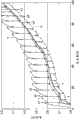
Fig. 2 is the measured data of the correlationship of expression " open-circuit voltage-charge rate ".
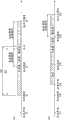
Fig. 3 is the figure during the application of expression discharge side table and charged side table.
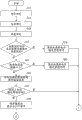
Fig. 4 A is the figure of the motion flow of expression operational part 24.
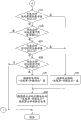
Fig. 4 B is the figure of the motion flow of expression operational part 24.
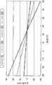
Fig. 5 is the figure of expression " open-circuit voltage-environment temperature " characteristic.
Embodiment
Below, with reference to accompanying drawing the mode that is used for embodiment of the present invention is described.Fig. 1 is the one-piece construction figure that has as the battery monitoring system 1 of the battery condition detection apparatus 20 of an embodiment of the invention.Battery monitoring system 1 possesses: secondary cell 10 and being used to detects the battery condition detection apparatus 20 of the state of secondary cell 10.As the concrete example of secondary cell 10, can enumerate lithium ion battery, Ni-MH battery etc.Battery condition detection apparatus 20 possesses voltage-level detector 21, Temperature Detector 22, storer 23 and operational part 24.Battery condition detection apparatus 20 also can possess the current detector 27 of the charging and discharging currents (input and output electric current) that is used to detect secondary cell 10.These inscapes of voltage-level detector 21 battery condition detection apparatus such as grade 20 for example are made up of integrated circuit.
Voltage-level detector 21 is the voltage detection units that are used to detect the output voltage of secondary cell 10.Voltage-level detector 21 outputs to operational part 24 with the detection data of the output voltage of secondary cell 10.And; Voltage-level detector 21 with the charging and discharging currents (input and output electric current) of secondary cell 10 at least the output voltage of the secondary cell 10 under the following state of predetermined first threshold (for example, zero or than zero big slightly value) detect as the open-circuit voltage of secondary cell 10.And; Voltage-level detector 21 also can be; Two interpolar voltages of will be at two interpolars of stable secondary cell 10 open circuit or recording when high impedance arranged, or (for example at the holding state electric current of the external unit (for example portable equipment such as mobile phone, game machine) that links to each other with battery condition detection apparatus 20 with secondary cell 10; Below the 1mA) load under the two interpolar voltages that record, detect as the open-circuit voltage of secondary cell 10.
In addition; Operational part 24 is that charge rate is calculated the unit; It will be by the open-circuit voltage after the charging of voltage-level detector 21 detected secondary cells 10; Be applied to represent first battery behavior of the relation between the charge rate of open-circuit voltage and secondary cell 10 after the charging of secondary cell 10, calculate the charge rate of secondary cell 10, will be by the open-circuit voltage after the discharge of voltage-level detector 21 detected secondary cells 10; Be applied to represent second battery behavior of the relation between the charge rate of open-circuit voltage and secondary cell 10 after the discharge of secondary cell 10, calculate the charge rate of secondary cell 10.Be used for confirming that first performance data of first battery behavior and second performance data that is used for definite second battery behavior are stored in storer 23 in advance.
So-called charge rate, be meant will be at that time constantly the full charge capacity of secondary cell 10 as the meaning of the ratio of the residual capacity of representing secondary cell 10 at 100 o'clock with percent.Expression utilizes correction chart or correction function to represent for the battery behavior of the correlationship of calculating charge rate needed " open-circuit voltage-charge rate ".The data in the correction chart and the coefficient of correction function are used as performance data and are stored in the storer 23.Operational part 24 corresponding to the open-circuit voltage that is recorded by voltage-level detector 21, carries out calculating and revising of charge rate according to the correction chart or the correction function that have reflected the performance data of reading from storer 23.
To " open-circuit voltage-charge rate " this correlationship, the performance data of determining according to results measured (with reference to Fig. 2) in advance is stored in storer 23.In Fig. 2, family curve a is the measured data that repeats when making from the state of residual capacity 0mAh charging scheduled volume (50mAh) that its schedule time, (4 hours) were non-loaded.Visible from family curve a, two interpolar voltages rise in the charging, and under the state of 4 hours non-loaded a1, a2, a3, open-circuit voltage reduces.In this case, the information of " open-circuit voltage-charge rate " under the back 4 hours no-load conditions of charging is used as and is stored in storer 23 to the open-circuit voltage data of each charge rate after the charging of secondary cell 10.In addition, family curve c is with back 4 hours no-load conditions of charging open-circuit voltage binding and curve of obtaining down.
On the other hand, family curve b is the measured data that repeats when the state discharge scheduled volume (50mAh) from full charging makes that its schedule time, (4 hours) were non-loaded.Visible from family curve b, open-circuit voltage reduces in the discharge, at 4 hours non-loaded b1, b2, b3 ... State under, open-circuit voltage rises.In this case, the information of " open-circuit voltage-charge rate " under the back 4 hours no-load conditions of discharging is used as and is stored in storer 23 to the open-circuit voltage data of each charge rate after the discharge of secondary cell 10.In addition, family curve d is that open-circuit voltage with back 4 hours no-load conditions of discharge links and the curve that obtains.Family curve e when family curve d and state from full charging use and often discharge with 3mA is roughly overlapping.
In addition, about above-mentioned charge/discharge capacity 50mAh, non-loaded time 4 hours, be made as optimum value with disposal route and be advisable according to system.
The open-circuit voltage data to each charge rate to after the open-circuit voltage data of each charge rate and the discharge that are stored in after the discharge in the storer 23 can be the voltage data that records, but also can be that the arbitrary side to the open-circuit voltage data of each charge rate to after the open-circuit voltage data of each charge rate and the discharge after the charging using through the voltage data of confirming with the opposing party's difference and representes.That is, arbitrary side's open-circuit voltage data can directly be stored in its value of measuring voltage in the storer 23.Thus, can cut down storer 23 desired memory capacity.Operational part 24 according to arbitrary side's open-circuit voltage data and the opposing party's differential voltage data can this opposing party of computing the open circuit data voltage.
Open-circuit voltage data after the potential difference to each charge rate of family curve a and family curve b is equivalent to charge and the differential voltage data between the open-circuit voltage data after the discharge.For example, the open-circuit voltage data after the charging are stored as measuring voltage data, the open-circuit voltage data after the discharge are stored as the differential voltage data.Also can be conversely.As shown in Figure 2, the absolute value of open-circuit voltage is to be unit to count V, and is relative therewith, and potential difference is to be unit with tens of mV.Therefore; Open-circuit voltage data through the arbitrary side after will charge back and the discharge are stored with the potential difference data; Compare with the situation that both open-circuit voltages of discharge back are stored with its absolute value with the back of will charging, can cut down the requirement of the memory capacity of storer 23 significantly.
Disposal route when next, operational part 24 being calculated charge rate describes.Operational part 24; For example; According to from the discharge capacity of charging finish time of secondary cell 10 and the secondary cell elapsed time of 10 charging finish times, select to store after the charging to after " open-circuit voltage-charge rate " of the open-circuit voltage data set of each charge rate and the discharge to a certain side in " open-circuit voltage-charge rate " of the open-circuit voltage data set of each charge rate.Then, according to selected table, calculate charge rate.The figure during the charged side table or the side table that discharges has been used in Fig. 3 expression selection.During till being equivalent to from the charging t1 zero hour to the charging t2 finish time between the charge period of secondary cell 10.
Shown in Fig. 3 (a); Operational part 24; Be judged as behind the charging finish time t2, because non-loaded or micro discharge and (for example not producing under the situation of the output voltage stabilization of secondary cell 10 under the situation of the discharge more than the predetermined reference capacity A1; Passed through from the charging t2 finish time to voltage till the stable t3 constantly during (promptly; Above-mentioned stable stand-by period T) under the situation), be " open-circuit voltage after the charging " by voltage-level detector 21 detected open-circuit voltages, calculate charge rate according to the charged side table.
But; Load condition behind the charging t2 finish time may not be a no-load condition; Also sometimes through with secondary cell 10 being the not shown external unit (for example, mobile phone, game machine etc.) of power supply, form the state of the micro discharge of the current sinking that continues to flow through several mA degree.Therefore, will be considered to inappropriate handling as " open-circuit voltage after the charging " from the charging t2 finish time detected open-circuit voltage of the moment after through the time to a certain degree.Therefore, can according to the charged side table calculate charge rate during, must be that elapsed time from the charging t2 finish time is less than predetermined A2 reference time.
In addition, reference capacity A1 and reference time A2 confirm as suitable with the current sinking of the external unit of supplying power according to the characteristic of the battery of secondary cell 10, from secondary cell 10.
In addition; Operational part 24; When having taken place behind the t2 under the situation of the discharge more than the reference capacity A1 finish time in charging, if do not take place certain discharge capacity or discharge time, which table that then is difficult to differentiate with in discharge side table and the charged side table is that benchmark can be calculated charge rate accurately.Therefore, for example, operational part 24; Behind charging finish time t2, end the processing of calculating charge rate, up to certain discharge capacity corresponding with the characteristic of the battery of secondary cell 10 etc. taking place (for example according to the output voltage of secondary cell 10; Reference capacity B1 greater than reference capacity A1) or discharge time (for example; Be longer than B2 reference time of A2 reference time) till, thus, can prevent that the error of calculating of charge rate from becoming big.
In addition, shown in Fig. 3 (a), operational part 24; Behind the charging t2 finish time, certain discharge capacity (for example, reference capacity B1) back is taking place (perhaps through micro discharge; The self-charging elapsed time that t2 rises the finish time has been passed through the predetermined above back of B2 reference time), stablize under the later still stable situation of the t3 zero hour at voltage at the output voltage of secondary cell 10, be " open-circuit voltage after the discharge " by voltage-level detector 21 detected open-circuit voltages; Calculate charge rate, in addition according to discharge side table; Operational part 24 is shown in Fig. 3 (b), behind the charging t12 finish time; Owing to the big discharge (t13 ~ t14) certain discharge capacity has taken place (for example that surpasses micro discharge; Reference capacity B) back (perhaps, the self-charging elapsed time that t2 rises the finish time has been passed through the predetermined above back of B2 reference time), at the output voltage of secondary cell 10 after voltage is stablized the t15 zero hour under the still stable situation; Be used as " open-circuit voltage after the discharge " by voltage-level detector 21 detected open-circuit voltages, calculate charge rate according to discharge side table.In addition, in Fig. 3 (b), stablize from the discharge t14 finish time to voltage till the t15 zero hour during be equivalent to above-mentioned stable stand-by period T.
Fig. 4 A, Fig. 4 B be secondary cell 10 charge rate calculate treatment scheme.Operational part 24 begins to follow the action of this flow process under the situation of the charging and discharging currents that has detected the secondary cell 10 below the predetermined first threshold.
The stable stand-by period is calculated portion 26; Under a certain at least side of the environment temperature Ta of secondary cell 10 and charging and discharging currents situation with respect to the change that predetermined benchmark has taken place before through the stable stand-by period T that has calculated to exceed; Use is accompanied by this change and the value that changes is calculated again as stated and stablized stand-by period T, and the register value that will stablize stand-by period T is updated to the value of calculating once more (step S17 ~ 23).
For example, detected under the situation of the temperature that surpasses reference value in during certain, the moment after this detections is set the stable stand-by period T of needs once more.Because even the change of the environment temperature of secondary cell 10 is stable, and postpone if having time up to the temperature stabilization of secondary cell 10 self, therefore, battery statuss such as open-circuit voltage of measuring sometimes or battery temperature are unstable.Therefore, through estimate the residual capacity state of secondary cell 10 according to the battery statuss such as environment temperature Ta before environment temperature Ta or the charging and discharging currents change, its evaluated error possibly amplified.But, stablize stand-by period T through as step S17 ~ 23, prolonging, can suppress the amplification of such evaluated error.Like this, through stablize stand-by period T having detected to prolong under the situation of temperature variation etc., can measure battery status such as open-circuit voltage and environment temperature more accurately, the postponement in the period of calculating of the charge rate of stating after making can improve the precision of the charge rate calculated.
For example; In step S17; Under the situation of the change that in the charging and discharging currents that detects the secondary cell 10 below the predetermined first threshold is during certain hour, has detected the environment temperature Ta that surpasses reference value; The stable stand-by period calculates portion 26 and calculates with the capability retention K that has calculated once more and the corresponding stable stand-by period T of environment temperature Ta after changing, and register value is updated to this value of calculating once more (step S19).
In addition; For example, in step S21, the charging and discharging currents that flows through the above secondary cell 10 of predetermined threshold value is once more the condition of calculation stability stand-by period T; Also become the variable of capability retention K; Therefore, the stable stand-by period calculates portion 26 and calculates with the environment temperature K that has measured once more and the corresponding stable stand-by period T of capability retention K after changing, and register value is updated to this value of calculating once more (step S23).
In step S17, S21; Operational part 24 (for example all surpasses at the environment temperature Ta of secondary cell 10 and charging and discharging currents under the situation of predetermined benchmark; Be under the situation of the change in certain scope); The register value that only will stablize stand-by period T deducts predetermined value (step S25), judges whether to have passed through stable stand-by period T, and whether the register value of promptly stablizing stand-by period T is zero (step S27).If, then do not return beginning most of this flow process through stablizing stand-by period T.
If passed through stand-by period T; Then operational part 24 is according to the performance data that is stored in expression " open-circuit voltage-charge rate " characteristic (Fig. 5) in the storer 23 in advance; Corresponding to stablizing the environment temperature (environment temperature that perhaps in step S15, records) that records under the later voltage steady state (SS) of stand-by period T, will be modified to 25 ℃ of conditions (step S29) stablizing the open-circuit voltage (open-circuit voltage that perhaps in step S11, records) that the later voltage steady state (SS) of stand-by period T records." open-circuit voltage-charge rate " characteristic (Fig. 5) expression is the side-play amount of the open-circuit voltage at each temperature of benchmark with 25 ℃.In Fig. 5, show the side-play amount of the open-circuit voltage that is directed against each charge rate of secondary cell 10.Thus, can suppress the increase of calculating error of charge rate with temperature correction open-circuit voltage.
In Fig. 4 B, operational part 24 judges that discharge capacity that self-charging rises the finish time is whether more than the first predetermined reference capacity B1 (step S31).Operational part 24 is being judged as under the situation more than the reference capacity B1; Shown in Fig. 3 (b); Behind the charging t1 finish time, produce big discharge; Produce at it that back load condition non-loaded or micro discharge continues thereby output voltage is stable in timing t 15, selected to have confirmed that the charge rate after the discharge and " open-circuit voltage-charge rate " of the relation of open-circuit voltage calculate with showing (step S33) as charge rate.
On the other hand, operational part 24 is being judged as in step S31 not under the situation more than the reference capacity B1, judges the whether not enough second predetermined reference capacity A1 (step S35) of discharge capacity that self-charging rises the finish time.Reference capacity A1 is the value littler than reference capacity B1.Operational part 24 is not under the situation of not enough reference capacity A1 being judged as; The self-charging discharge capacity increase that the finish time, t2 rose; Being difficult to distinguish by voltage-level detector 21 detected open-circuit voltages is open-circuit voltage or the open-circuit voltage after the charging after the discharge, does not implement the renewal of the register value of charge rate.
When operational part 24 is judged as under the situation of not enough reference capacity A1, judge that elapsed time that self-charging rises the finish time is whether more than the predetermined first reference time B2 (step S37) in step S35.Operational part 24 is being judged as under the situation more than the reference time B2, will select discharge side table to calculate with table (step S33) as charge rate by voltage-level detector 21 detected open-circuit voltages as " open-circuit voltage after the discharge ".The processing of step S43 afterwards is same as described above.For example; If the situation of Fig. 3 (a); Reference time B2 through t5 constantly to spread of voltage constantly till the t6 during select discharge side table, if the situation of Fig. 3 (b), from voltage stable t15 constantly to spread of voltage constantly till the t16 during select the side table that discharges.Spread of voltage moment t6 or t16 are that charging and discharging currents surpasses the moment that can open-circuit voltage be regarded as unsettled predetermined value.
On the other hand; In step S35, be judged as the operational part 24 of not enough reference capacity A1; Under the situation that in step S37, is judged as not enough reference time of B2, judge whether not enough second A2 reference time (step S39) that is scheduled to of discharge capacity that self-charging rises the finish time.Reference time, A2 was than the short length of B2 reference time.Operational part 24; Being judged as not is under the situation of deficiency A2 reference time; The self-charging elapsed time that t2 rises the finish time is elongated; Being difficult to distinguish by voltage-level detector 21 detected open-circuit voltages is open-circuit voltage or the open-circuit voltage after the charging after the discharge, does not implement the renewal of the register value of charge rate.
Be judged as in step S39 when operational part 24 under the situation of deficiency A2 reference time, will select the charged side table to calculate with table (step S41) by voltage-level detector 21 detected open-circuit voltages as " open-circuit voltage after the charging " as charge rate.For example, if the situation of Fig. 3 (a), from voltage stable t3 constantly to reference time A2 through selection charged side table in during till the t4 constantly.
Therefore; According to the above embodiments; Open-circuit voltage to after open-circuit voltage after the charging and the discharge is distinguished mensuration; And use the charged side table selectively and calculate with table as charge rate with discharge side table, can calculate charge rate accurately thus all the time and irrelevant with the state after charging back and the discharge.
More than, preferred embodiment of the present invention is illustrated, but the present invention is not limited to the foregoing description, without departing from the scope of the invention can be the foregoing description various distortion in addition, improvement and displacement.
For example; In Fig. 2; Also can the family curve d under the no-load condition after family curve c under the no-load condition after the charging and/or the discharge be handled through curve fitting (curve fit) and represent, should be stored in advance in the storer 23 by polynomial each coefficient with polynomial approximate model function.Thus, compare to the open-circuit voltage data conditions of each charge rate, can cut down the capacity of storer 23 with direct storage.
The application of this world is advocated based on Japanese patent application 2010-035128 number the right of priority of filing an application on February 19th, 2010, and 2010-035128 number full content is quoted in the application of this world.
Symbol description
1 battery monitoring system
10 secondary cells
20 battery condition detection apparatus
21 voltage-level detectors
22 Temperature Detectors
23 storeies
24 operational parts
26 stablize the stand-by period calculates portion
27 current detectors
Claims (10)
1. battery condition detection apparatus is characterized in that possessing:
Voltage detection unit, it is used to detect the open-circuit voltage of secondary cell; And
Charge rate is calculated the unit; It will be by the open-circuit voltage after the charging of the detected said secondary cell of said voltage detection unit; Be applied to represent first battery behavior of the relation between the charge rate of open-circuit voltage and said secondary cell after the charging of said secondary cell; Calculate said charge rate; Will be by the open-circuit voltage after the discharge of the detected said secondary cell of said voltage detection unit, be applied to represent second battery behavior of the relation between the charge rate of open-circuit voltage and said secondary cell after the discharge of said secondary cell, calculate said charge rate.
2. battery condition detection apparatus according to claim 1, wherein,
Under the situation more than first reference capacity, said charge rate is calculated the unit and is selected said second battery behavior of application to calculate said charge rate in the discharge capacity after the charging of said secondary cell.
3. battery condition detection apparatus according to claim 2, wherein,
Said discharge capacity less than said first reference capacity and from elapsed time of charging finish time of said secondary cell under the situation more than first reference time, said charge rate is calculated the unit and is selected to use said second battery behavior and calculate said charge rate.
4. battery condition detection apparatus according to claim 3, wherein,
Said discharge capacity less than said first reference capacity and the situation of said elapsed time less than said first reference time under, said charge rate is calculated the unit and select to be used said first battery behavior and calculate said charge rate.
5. battery condition detection apparatus according to claim 1, wherein,
Said battery condition detection apparatus possesses: storage unit, its storage are used for confirming first performance data and second performance data that is used for confirming said second battery behavior of said first battery behavior,
The open-circuit voltage data that constitute said first performance data are used with the opposing party's differential voltage data with arbitrary side in the open-circuit voltage data that constitute said second performance data and are represented.
6. a battery status detection method is characterized in that,
Detect the open-circuit voltage of secondary cell,
With the open-circuit voltage after the charging of said detected said secondary cell, be applied to represent first battery behavior of the relation between the charge rate of open-circuit voltage and said secondary cell after the charging of said secondary cell, calculate said charge rate,
With the open-circuit voltage after the discharge of said detected said secondary cell, be applied to represent second battery behavior of the relation between the charge rate of open-circuit voltage and said secondary cell after the discharge of said secondary cell, calculate said charge rate.
7. battery status detection method according to claim 6, wherein,
, under the situation more than first reference capacity, select to use said second battery behavior and calculate said charge rate in the discharge capacity after the charging of said secondary cell.
8. battery status detection method according to claim 7, wherein,
Said discharge capacity less than said first reference capacity and from elapsed time of charging finish time of said secondary cell under the situation more than first reference time, select to use said second battery behavior and calculate said charge rate.
9. battery status detection method according to claim 8, wherein,
Said discharge capacity less than said first reference capacity and the situation of said elapsed time less than said first reference time under, select to use said first battery behavior and calculate said charge rate.
10. battery status detection method according to claim 6, wherein,
Storage is used for confirming first performance data and second performance data that is used for confirming said second battery behavior of said first battery behavior,
The open-circuit voltage data that constitute said first performance data are used with the opposing party's differential voltage data with arbitrary side in the open-circuit voltage data that constitute said second performance data and are represented.
Applications Claiming Priority (3)
| Application Number | Priority Date | Filing Date | Title |
|---|---|---|---|
| JP2010035128A JP5732725B2 (en) | 2010-02-19 | 2010-02-19 | Battery state detection device |
| JP2010-035128 | 2010-02-19 | ||
| PCT/JP2011/050961 WO2011102179A1 (en) | 2010-02-19 | 2011-01-20 | Battery state detection device |
Publications (2)
| Publication Number | Publication Date |
|---|---|
| CN102762995A true CN102762995A (en) | 2012-10-31 |
| CN102762995B CN102762995B (en) | 2014-11-19 |
Family
ID=44482780
Family Applications (1)
| Application Number | Title | Priority Date | Filing Date |
|---|---|---|---|
| CN201180009971.7A Active CN102762995B (en) | 2010-02-19 | 2011-01-20 | Battery state detection device and battery state detection method |
Country Status (4)
| Country | Link |
|---|---|
| US (1) | US20120290236A1 (en) |
| JP (1) | JP5732725B2 (en) |
| CN (1) | CN102762995B (en) |
| WO (1) | WO2011102179A1 (en) |
Cited By (4)
| Publication number | Priority date | Publication date | Assignee | Title |
|---|---|---|---|---|
| CN107076802A (en) * | 2014-12-05 | 2017-08-18 | 古河电气工业株式会社 | Secondary cell condition checkout gear and secondary cell condition detection method |
| CN111308357A (en) * | 2020-04-01 | 2020-06-19 | 一汽解放汽车有限公司 | Battery capacity estimation method, battery management system, vehicle, and storage medium |
| CN112051433A (en) * | 2019-06-06 | 2020-12-08 | 松下电器(美国)知识产权公司 | Open circuit voltage measuring method, open circuit voltage measuring device, and recording medium |
| CN117317418A (en) * | 2023-11-29 | 2023-12-29 | 珠海智锐科技有限公司 | Battery control method of BMS management system |
Families Citing this family (22)
| Publication number | Priority date | Publication date | Assignee | Title |
|---|---|---|---|---|
| JP5870590B2 (en) * | 2011-09-29 | 2016-03-01 | ミツミ電機株式会社 | Battery state measuring method and battery state measuring apparatus |
| JP2013083612A (en) * | 2011-10-12 | 2013-05-09 | Mitsumi Electric Co Ltd | Battery state measurement method and battery state measurement apparatus |
| US9570931B2 (en) | 2011-12-22 | 2017-02-14 | Panasonic Intellectual Property Corporation Of America | Electronic device and electronic device charging system |
| JP5768772B2 (en) * | 2012-06-29 | 2015-08-26 | 株式会社豊田自動織機 | Power storage system and charging rate estimation method |
| TWI460453B (en) * | 2012-09-28 | 2014-11-11 | Metal Ind Res & Dev Ct | Estimating system for state of charge of battery by additive synthesis of two components of mutually perpendicular and estimating method thereof |
| CN102928785A (en) * | 2012-10-16 | 2013-02-13 | 西安思坦仪器股份有限公司 | Battery power measuring instrument and measuring method |
| JP2014102248A (en) * | 2012-10-24 | 2014-06-05 | Gs Yuasa Corp | Power storage state detection apparatus |
| US9552031B2 (en) | 2013-12-20 | 2017-01-24 | Facebook, Inc. | Power shelf for computer servers |
| DE102014200673A1 (en) * | 2014-01-16 | 2015-07-16 | Robert Bosch Gmbh | Method for monitoring a battery |
| FR3025889B1 (en) * | 2014-09-12 | 2016-11-18 | Commissariat Energie Atomique | MANAGING THE RECHARGE OF THE BATTERY OF AN ELECTRIC VEHICLE |
| US10386421B2 (en) * | 2015-09-14 | 2019-08-20 | Facebook, Inc. | Energy based battery backup unit testing |
| US10063092B2 (en) | 2015-10-02 | 2018-08-28 | Facebook, Inc. | Data center power network with multiple redundancies |
| US9986658B2 (en) | 2015-12-03 | 2018-05-29 | Facebook, Inc | Power connection clip for a shelf in a server rack |
| JP6830318B2 (en) | 2016-01-15 | 2021-02-17 | 株式会社Gsユアサ | Power storage element management device, power storage element module, vehicle and power storage element management method |
| JP6930572B2 (en) * | 2016-01-15 | 2021-09-01 | 株式会社Gsユアサ | Power storage element management device, power storage element module, vehicle and power storage element management method |
| US10123450B2 (en) | 2016-05-12 | 2018-11-06 | Facebook, Inc. | High voltage direct current power generator for computer server data centers |
| KR102458526B1 (en) * | 2018-02-07 | 2022-10-25 | 주식회사 엘지에너지솔루션 | Apparatus and method for estimating soc base on operating state of battery |
| JP6958427B2 (en) * | 2018-02-27 | 2021-11-02 | トヨタ自動車株式会社 | Rechargeable battery system |
| JP7111969B2 (en) | 2018-10-30 | 2022-08-03 | ミツミ電機株式会社 | Electronic device and its control method |
| JP7044044B2 (en) * | 2018-12-07 | 2022-03-30 | トヨタ自動車株式会社 | Deterioration degree estimation device for secondary batteries and deterioration degree estimation method for secondary batteries |
| JP7244746B2 (en) | 2019-02-22 | 2023-03-23 | ミツミ電機株式会社 | ELECTRONIC DEVICE AND ITS STATE DETERMINATION METHOD |
| KR20210074005A (en) * | 2019-12-11 | 2021-06-21 | 주식회사 엘지에너지솔루션 | Battery management system, battery management method, battery pack, and electric vehicle |
Citations (4)
| Publication number | Priority date | Publication date | Assignee | Title |
|---|---|---|---|---|
| JPH11289685A (en) * | 1998-04-01 | 1999-10-19 | Toshiba Battery Co Ltd | Device for detecting charged state of secondary battery |
| CN1182407C (en) * | 2003-01-16 | 2004-12-29 | 华南理工大学 | Method for measuring electric quantity of lithium ion batteries and its device |
| JP2007327971A (en) * | 2002-11-27 | 2007-12-20 | Fuji Electric Device Technology Co Ltd | Measuring device of remaining battery life |
| WO2010003361A1 (en) * | 2008-07-08 | 2010-01-14 | 奇瑞汽车股份有限公司 | Method and device for forecasting battery charge |
Family Cites Families (3)
| Publication number | Priority date | Publication date | Assignee | Title |
|---|---|---|---|---|
| US4344142A (en) * | 1974-05-23 | 1982-08-10 | Federal-Mogul Corporation | Direct digital control of rubber molding presses |
| JP2878953B2 (en) * | 1993-12-27 | 1999-04-05 | 本田技研工業株式会社 | Method for detecting remaining capacity of battery for electric vehicle |
| JP4631880B2 (en) * | 2007-07-30 | 2011-02-16 | ミツミ電機株式会社 | Battery status detection method |
-
2010
- 2010-02-19 JP JP2010035128A patent/JP5732725B2/en active Active
-
2011
- 2011-01-20 US US13/519,365 patent/US20120290236A1/en not_active Abandoned
- 2011-01-20 WO PCT/JP2011/050961 patent/WO2011102179A1/en active Application Filing
- 2011-01-20 CN CN201180009971.7A patent/CN102762995B/en active Active
Patent Citations (4)
| Publication number | Priority date | Publication date | Assignee | Title |
|---|---|---|---|---|
| JPH11289685A (en) * | 1998-04-01 | 1999-10-19 | Toshiba Battery Co Ltd | Device for detecting charged state of secondary battery |
| JP2007327971A (en) * | 2002-11-27 | 2007-12-20 | Fuji Electric Device Technology Co Ltd | Measuring device of remaining battery life |
| CN1182407C (en) * | 2003-01-16 | 2004-12-29 | 华南理工大学 | Method for measuring electric quantity of lithium ion batteries and its device |
| WO2010003361A1 (en) * | 2008-07-08 | 2010-01-14 | 奇瑞汽车股份有限公司 | Method and device for forecasting battery charge |
Cited By (7)
| Publication number | Priority date | Publication date | Assignee | Title |
|---|---|---|---|---|
| CN107076802A (en) * | 2014-12-05 | 2017-08-18 | 古河电气工业株式会社 | Secondary cell condition checkout gear and secondary cell condition detection method |
| US10656210B2 (en) | 2014-12-05 | 2020-05-19 | Furukawa Electric Co., Ltd. | Secondary battery state detection device and secondary battery state detection method |
| CN107076802B (en) * | 2014-12-05 | 2020-12-29 | 古河电气工业株式会社 | Secondary battery state detection device and secondary battery state detection method |
| CN112051433A (en) * | 2019-06-06 | 2020-12-08 | 松下电器(美国)知识产权公司 | Open circuit voltage measuring method, open circuit voltage measuring device, and recording medium |
| CN111308357A (en) * | 2020-04-01 | 2020-06-19 | 一汽解放汽车有限公司 | Battery capacity estimation method, battery management system, vehicle, and storage medium |
| CN117317418A (en) * | 2023-11-29 | 2023-12-29 | 珠海智锐科技有限公司 | Battery control method of BMS management system |
| CN117317418B (en) * | 2023-11-29 | 2024-02-13 | 珠海智锐科技有限公司 | Battery control method of BMS management system |
Also Published As
| Publication number | Publication date |
|---|---|
| JP5732725B2 (en) | 2015-06-10 |
| WO2011102179A1 (en) | 2011-08-25 |
| CN102762995B (en) | 2014-11-19 |
| JP2011169817A (en) | 2011-09-01 |
| US20120290236A1 (en) | 2012-11-15 |
Similar Documents
| Publication | Publication Date | Title |
|---|---|---|
| CN102762995B (en) | Battery state detection device and battery state detection method | |
| JP5282789B2 (en) | Battery capacity detection device for lithium ion secondary battery | |
| JP5541112B2 (en) | Battery monitoring device and battery monitoring method | |
| JP5393956B2 (en) | Battery full charge capacity detection method | |
| CN102144171B (en) | Battery state detection device and battery pack incorporating same, and battery state detection method | |
| US8253380B2 (en) | Characteristic tracking method and circuit for a battery module | |
| CN102282478B (en) | Battery pack, semiconductor integrated circuit, remaining capacity correcting method, and storage medium | |
| CN102725647A (en) | Battery state detection device and method | |
| JP5535968B2 (en) | CHARGE RATE ESTIMATION DEVICE, CHARGE RATE ESTIMATION METHOD, AND PROGRAM | |
| US20160011273A1 (en) | Method and apparatus for determining a capacity of a battery | |
| CN101443949B (en) | Method and apparatus for controlling battery | |
| JP6546452B2 (en) | Battery remaining amount estimating device, battery remaining amount estimating system, and battery pack | |
| CN102084262A (en) | Battery state detection device | |
| JP6525648B2 (en) | Battery capacity estimation system, battery capacity estimation method and battery capacity estimation program | |
| CN101930056B (en) | Method for predicting power backup time of battery | |
| JP2010085243A (en) | Method of detecting full charge capacity of backup battery | |
| CN104698385A (en) | Cell state calculation apparatus and cell state calculation method | |
| JP2002017045A (en) | Secondary battery device | |
| JP6991591B2 (en) | How to predict the state of charge of the battery | |
| KR101547004B1 (en) | Apparatus and method for estimating state of health of battery | |
| TWI528043B (en) | Battery SOC/SOH estimation circuit | |
| CN110687458A (en) | Terminal battery electric quantity determination method and device | |
| KR101277733B1 (en) | Apparatus and method for estimating state of charge of battery | |
| CN104166097A (en) | Battery electric quantity measuring method | |
| JP4329543B2 (en) | Battery level measuring device |
Legal Events
| Date | Code | Title | Description |
|---|---|---|---|
| C06 | Publication | ||
| PB01 | Publication | ||
| C10 | Entry into substantive examination | ||
| SE01 | Entry into force of request for substantive examination | ||
| C14 | Grant of patent or utility model | ||
| GR01 | Patent grant |