CN1026866C - Upsetting press for reducing width of rolling stock - Google Patents
Upsetting press for reducing width of rolling stock Download PDFInfo
- Publication number
- CN1026866C CN1026866C CN91105466A CN91105466A CN1026866C CN 1026866 C CN1026866 C CN 1026866C CN 91105466 A CN91105466 A CN 91105466A CN 91105466 A CN91105466 A CN 91105466A CN 1026866 C CN1026866 C CN 1026866C
- Authority
- CN
- China
- Prior art keywords
- connecting rod
- edging mill
- pressure block
- rod head
- width
- Prior art date
- Legal status (The legal status is an assumption and is not a legal conclusion. Google has not performed a legal analysis and makes no representation as to the accuracy of the status listed.)
- Expired - Lifetime
Links
- 238000005096 rolling process Methods 0.000 title claims abstract description 6
- 239000004519 grease Substances 0.000 claims abstract description 29
- 238000003825 pressing Methods 0.000 claims abstract description 12
- 238000005461 lubrication Methods 0.000 claims abstract description 7
- 230000002706 hydrostatic effect Effects 0.000 claims abstract description 4
- 238000007688 edging Methods 0.000 claims description 33
- 230000033001 locomotion Effects 0.000 claims description 13
- 238000005304 joining Methods 0.000 claims description 9
- 239000002826 coolant Substances 0.000 claims description 7
- 238000001816 cooling Methods 0.000 claims description 7
- 239000000969 carrier Substances 0.000 abstract 1
- 239000003921 oil Substances 0.000 description 19
- 230000001050 lubricating effect Effects 0.000 description 6
- 230000000694 effects Effects 0.000 description 5
- 238000006073 displacement reaction Methods 0.000 description 4
- 230000005540 biological transmission Effects 0.000 description 2
- 230000002349 favourable effect Effects 0.000 description 2
- 239000000314 lubricant Substances 0.000 description 2
- 239000010687 lubricating oil Substances 0.000 description 2
- 238000003754 machining Methods 0.000 description 2
- 238000000034 method Methods 0.000 description 2
- 229910000906 Bronze Inorganic materials 0.000 description 1
- RYGMFSIKBFXOCR-UHFFFAOYSA-N Copper Chemical compound [Cu] RYGMFSIKBFXOCR-UHFFFAOYSA-N 0.000 description 1
- 241000446313 Lamella Species 0.000 description 1
- 239000010974 bronze Substances 0.000 description 1
- 238000005266 casting Methods 0.000 description 1
- 239000010949 copper Substances 0.000 description 1
- 229910052802 copper Inorganic materials 0.000 description 1
- KUNSUQLRTQLHQQ-UHFFFAOYSA-N copper tin Chemical compound [Cu].[Sn] KUNSUQLRTQLHQQ-UHFFFAOYSA-N 0.000 description 1
- 230000003247 decreasing effect Effects 0.000 description 1
- 238000009826 distribution Methods 0.000 description 1
- 238000012423 maintenance Methods 0.000 description 1
- 239000000463 material Substances 0.000 description 1
- 230000002035 prolonged effect Effects 0.000 description 1
Images

Classifications
-
- B—PERFORMING OPERATIONS; TRANSPORTING
- B30—PRESSES
- B30B—PRESSES IN GENERAL
- B30B1/00—Presses, using a press ram, characterised by the features of the drive therefor, pressure being transmitted directly, or through simple thrust or tension members only, to the press ram or platen
-
- B—PERFORMING OPERATIONS; TRANSPORTING
- B21—MECHANICAL METAL-WORKING WITHOUT ESSENTIALLY REMOVING MATERIAL; PUNCHING METAL
- B21J—FORGING; HAMMERING; PRESSING METAL; RIVETING; FORGE FURNACES
- B21J1/00—Preparing metal stock or similar ancillary operations prior, during or post forging, e.g. heating or cooling
- B21J1/04—Shaping in the rough solely by forging or pressing
-
- B—PERFORMING OPERATIONS; TRANSPORTING
- B21—MECHANICAL METAL-WORKING WITHOUT ESSENTIALLY REMOVING MATERIAL; PUNCHING METAL
- B21B—ROLLING OF METAL
- B21B15/00—Arrangements for performing additional metal-working operations specially combined with or arranged in, or specially adapted for use in connection with, metal-rolling mills
- B21B15/0035—Forging or pressing devices as units
-
- B—PERFORMING OPERATIONS; TRANSPORTING
- B21—MECHANICAL METAL-WORKING WITHOUT ESSENTIALLY REMOVING MATERIAL; PUNCHING METAL
- B21J—FORGING; HAMMERING; PRESSING METAL; RIVETING; FORGE FURNACES
- B21J3/00—Lubricating during forging or pressing
-
- B—PERFORMING OPERATIONS; TRANSPORTING
- B21—MECHANICAL METAL-WORKING WITHOUT ESSENTIALLY REMOVING MATERIAL; PUNCHING METAL
- B21J—FORGING; HAMMERING; PRESSING METAL; RIVETING; FORGE FURNACES
- B21J7/00—Hammers; Forging machines with hammers or die jaws acting by impact
- B21J7/02—Special design or construction
- B21J7/18—Forging machines working with die jaws, e.g. pivoted, movable laterally of the forging or pressing direction, e.g. for swaging
Abstract
In an upsetting press for reducing the width of rolling stock, particularly the slab width in hot-rolled wide strip roughing mills with tool carriers, which are disposed on either side of the slab edge, accommodate pressing tools and can be moved in the direction of reducing the slab with the help of a steering system, which is operated with the help of at least one crank gear, the connecting rod head of the crank gear is movably supported in an appropriately shaped pressure pan of the tool support and the connecting rod head has a sliding band with hydrostatic pressure lubrication, which corresponds at least to the length of the contact of the pressure pan, so that the highly loaded sliding surfaces between the connecting rod head and the pressure pan are adequately lubricated with grease, even if they move only slightly relative to one another.
Description
The present invention relates to a kind of edging mill that in hot wide band roughing train, is used to reduce width of rolling stock, particularly width of plate slab, have on the machine and be located at the stamper seat that slab seamed edge both sides are used to admit pressing mold, stamper seat can be towards the direction motion of reduction width of plate slab by means of a leverage that is driven by at least one crank driving mechanism.
The prospectus 2531591 of Germany discloses and a kind ofly has been used to reduce from the width of the slab of the different in width of conticaster and the edging mill of thickness.On edging mill, slab is repeatedly by the pressurizing tool of relative motion processing, and this moment, pressurizing tool can freely be followed the tracks of the feeding of slab, and these pressurizing tools are controlled so as to that its impulse stroke is carried out is slower, and idle stroke is then carried out comparatively fast.Edging mill also has the mould of a pair of processing seamed edge, and these moulds vertically affact on the seamed edge of slab, and edging mill also has makes a little moulds make quick reciprocating device.Mould is fixed in the mould seat, and this mould seat is driven by a crank driving mechanism and is hinged on the mould seat by link bolt.The required edging power of reduction width of plate slab must be reached on mould seat and the pressurizing tool by the link bolt bearing.The big frictional force that is produced has reduced the working (machining) efficiency of edging mill, and owing to the wearing and tearing of link bolt have increased maintenance cost greatly, not only makes edging mill but also the utilization rate of the whole piece roll train that comprises edging mill is also decreased.
In disclosed a kind of quick edging mill, the width for reduction slab in hot wide band roughing train is provided with pressing mold in the both sides of slab seamed edge in German patent application P3917398.4, and pressing mold is contained on the stamper seat.Drive in order to form reduction, each pressing mold moves to the direction of reduction width of plate slab by means of a leverage that is driven by crank driving mechanism together with affiliated stamper seat, and wherein, crank driving mechanism is located in the crank box.Crank driving mechanism is made up of two driven eccentric shafts, is provided with a connecting rod on each eccentric shaft, and its connecting rod head links to each other with stamper seat, the collaborative edging power of transmitting.Act on the stamper seat is a feed drive gearing that works in the slab direction of feed basically.By above-mentioned measure, can be controlled respectively the motion process of the propelling of the reduction pressurization of pressing mold and pressing mold.If feed drive gearing is designed to hydraulic cylinder, then can particularly advantageously press the moving movement of stroke-time function relation control hydraulic cylinder, the motion of the motion of pressing mold and the slab that sidepiece will pressurize all can be guaranteed under arbitrary amount of feeding synchronously.In pressure process, by the corresponding control of feeding cylinder, the sub-fraction of an angle of a connecting rod displacement and when idle running displacement several years angle only, therefore, in the bearing of connecting rod head, the lubricating arrangement structure can be set effectively.
From the described edging mill of patent application P3917398.4, task of the present invention is, provide a kind of connecting rod support and stamper seat, even if make it very big in edging power and can guarantee also under the situation that the connecting rod displacement angle is very little that connecting rod obtains very effectively and lubricated reliably.
Edging mill by classification of the present invention is characterised in that, but being bearing in to the connecting rod head relative motion of crank driving mechanism on the stamper seat one has on the Pressure Block of corresponding configuration, connecting rod head is provided with a slip panel with hydrostatic lubrication, and its length is equivalent to the contact length of Pressure Block at least.By these measures,, and when the connecting rod angle displacement is very little, can guarantee the lubricating oil film that one deck is stable even if when edging power is very big, still can control surface pressing between connecting rod and the stamper seat.In that the slip panel is set on the connecting rod head is another prerequisite of stablizing oil film between connecting rod head and the Pressure Block, and this is because the slip panel can be made and have high surface smoothness; If connecting rod head is directly processed, then because the size of connecting rod head is bigger, will making so with conventional lathe, high surface smoothness almost is impossible.
In addition, in order to help the lubricated of connecting rod, structure is designed to, makes the slip panel have the roughly uniform oil pocket of joining at it on the surface of Pressure Block, the grease channel that passes the connecting rod stretching, extension of crank driving mechanism feeds these and joins oil pocket.The uniform oil pocket of joining on the surface of slip panel can evenly be supplied with lubricant, especially more can bring into play its effect when connecting rod is laid down edging pressure.In this case, it is favourable that the grease pump that produces endurable pressure is adopted in suggestion, this grease pump is pressed to lubricating grease with high pressure at connecting rod release motion stage and is joined oil pocket through grease channel, make connecting rod head have trace to raise, lubricating grease is between the planar bearing shell that is pressed into slip panel and Pressure Block from join oil pocket with respect to the Pressure Block of stamper seat.For supply and the distribution that further improves lubricant, the suggestion connecting line both sides between crank driving mechanism supporting and connecting rod head supporting at least is in the scope of 45 ° of pressure angles approximately, is criss-cross oil-way joining to be provided with between the oil pocket.
In the another kind of version of the connecting rod lubrication device of crank driving mechanism, stamper seat is provided with cooling device in the Pressure Block zone, the viscosity that makes lubricating grease is at the very big pressure that can estimate and very controlled and remain within the predetermined range during elevated operating temperature, and makes the unlikely degree of danger that is diluted to infringement thrust bearing shell or slip panel of oil film.Fill inadequately part and damage oil film for the Surface Machining of reason slip panel not, advise that also the slip panel must not surpass 0.2 micron towards the rough surface height Ra on the surface of Pressure Block, in other words, should adopt mirror grinding processing to this surface of slip panel.The thrust bearing shell of using with the Pressure Block on the stamper seat blue or green made of copper and the aforementioned cooling device of Pressure Block combine, and the connecting rod head of crank driving mechanism can obtain to be enough to bear the grease lubrication of peak load.
For the cooling device that makes Pressure Block more can play cooling effect along the entire contact surface of Pressure Block and connecting rod head, this cooling device is formed by be the tortuous coolant channel that stretches along the width of this bearing shell below thrust bearing shell in stamper seat, and its related cooling agent enters and discharges interface and is located at respectively on the termination with respect to the two ends of thrust bearing shell.By coolant flow is carried out corresponding control, can accurately keep by calculating or test predetermined bearing temperature, thereby accurately keep the predetermined viscosity of lubricating grease.
In a favourable structure of the present invention, be provided with some devices to collect and grease is overflowed in suction at the end regions of thrust bearing shell and slip panel, i.e. those lubricating grease from overflowing between the sliding surface lentamente in the course of the work.By grease pump the oil quantity that is equivalent to overflow is joined oil pocket through additional being pressed into of grease channel, and enter between the sliding surface by joining oil pocket more as previously mentioned.
Further illustrate according to connecting rod lubrication device of the present invention by some embodiment below.In the accompanying drawings:
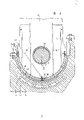
Fig. 1 is a horizontal sectional drawing of edging mill;
Fig. 2 is the enlarged drawing that is provided with the connecting rod head of slip panel and Pressure Block on stamper seat, that cooled off;
Fig. 3 is the vertical view of the slip panel that launched.
Fig. 1 is illustrated in the horizontal profile of the edging mill 1 width, sharp work that is used to reduce slab 2 in the hot wide band roughing train, slab almost be continuously by one be located at edging mill the place ahead but the detailed slab casting equipment supply of showing among the figure.The forward and backward driven roller 3,4 that is provided with at edging mill.Slab 2 passes slab edging frame by the direction of motion shown in the label 5.Edging mill has memorial archway 6.Crank box 9 leads on the framework memorial archway of edging mill adjustably.The adjustment of crank box realizes by means of a mechanical guiding mechanism 10.But the piston/cylinder barrel structure that also can adopt hydraulic is as guiding mechanism.
Be provided with the pressing mold 7 that is fixed on the stamper seat 8 in the both sides of slab 2.Pressing mold and stamper seat have one along normal direction, promptly perpendicular to transmission device 11 and a feed drive gearing 12 that tangentially, promptly is parallel to the slab effect of the reduction rolled piece width of slab 2 effect.The transmission device of reduction width of rolling stock is designed so that each stamper seat 8 moves by means of the direction of a slab that can be basically will be reduced towards its width by two eccentric shafts 13 leverages that drive, that comprise two connecting rods 14.Basically the feed drive gearing 12 along the effect of slab direction of feed acts on the stamper seat 8, and supporting is provided with on the crank box of two eccentric shafts within it.But being bearing in to connecting rod head 15 relative motions of connecting rod 14 on the stamper seat 8 one has on the Pressure Block 16 of corresponding configuration.
Fig. 2 is the enlarged drawing of the connecting rod head 15 of the crank driving mechanism 17 that is made of eccentric shaft.But being bearing in to this connecting rod head relative motion on the stamper seat 8 one has on the Pressure Block 16 of corresponding configuration.Connecting rod head has the slip panel 18 of a hydrostatic lubrication, and its length is equivalent to the contact length of Pressure Block 16 at least.Slip panel 18 is provided with the roughly uniform oil pocket 19 of joining at it on the surface of Pressure Block 16, pass grease channel 20 that the connecting rod of crank driving mechanism stretches and feed these and join oil pocket.Not shown grease duct can be joined with the ingate 21 of grease channel 20, and grease duct is joined with the grease pump that produces endurable pressure again.Pressure Block 16 on the stamper seat 8 is provided with one by containing the thrust bearing shell 22 that bronze material is made.Below thrust bearing shell, be provided with along the tortuous coolant channel 23 that stretches of the width of this bearing shell, what these passages had cooling agent respectively on the termination with respect to the two ends of thrust bearing shell enters and discharges interface 24.Accurate grinding processing is carried out on the surface towards Pressure Block of slip panel, made its rough surface height be no more than 0.2 micron.Slip panel 18 links to each other with connecting rod head 15 by screw 25, and additional bonding.End regions 26,27 at thrust bearing shell 22 and slip panel 18 is provided with collection and aspirates the device 28,29 that overflows grease.
Fig. 3 is the vertical view of the slip panel 18 that launched.On the surface of slip panel 18, be provided with the roughly uniform oil pocket 19 of joining, pass grease channel 20 that the connecting rod 14 of crank driving mechanism 17 stretches and feed these and join oil pocket.Connecting line both sides between the supporting 31 of crank driving mechanism and connecting rod head supporting 32 are in 45 ° the scope of pressure angle approximately, are provided with criss-cross oil-way 30 between oil pocket joining.
Even above-mentioned all measures guarantee also can obtain filling the lubricated of part under the very little situation of sliding surface between relative motion between the connecting rod head of crank driving mechanism and the Pressure Block on the stamper seat, that bear high capacity, its oil film thickness is in operation and can remains between the 5-15 micron, therefore, oil lamella can be diluted to lower value.Slip panel through mirror grinding combines with the accurate dosage of grease and controlled grease viscosity; again by additional water-cooled Pressure Block; can guarantee to form between the sliding surface desirable carrying lubricating oil film; and can reduce grease consumption, because prolonged the time swap of grease from the sliding surface to the gathering-device by these measures.
Claims (10)
1, a kind ofly in hot wide band roughing train, be used to reduce width of rolling stock, the edging mill of width of plate slab particularly, have on the machine and be provided with the stamper seat that slab seamed edge both sides are used to admit pressing mold, stamper seat can move towards the direction of reduction width of plate slab by means of a leverage that is driven by at least one crank driving mechanism, it is characterized in that, the connecting rod head (15) of crank driving mechanism (17) but relative motion be bearing on the stamper seat (8) one and have on the Pressure Block (16) of corresponding configuration, and connecting rod head (15) has the slip panel (18) of a hydrostatic lubrication, its length is equivalent to the angle that connects of Pressure Block (16) at least and touches length
2, press the edging mill of claim 1, it is characterized in that, slip panel (18) has the roughly uniform oil pocket (19) of joining at it on the surface of Pressure Block (16), pass grease channel (20) that the connecting rod (14) of crank driving mechanism (17) stretches and feed these and join oil pocket.
3, press the edging mill of claim 1 or 2, it is characterized in that, at least the connecting line both sides between the supporting (31) of crank driving mechanism and connecting rod head supporting (32) are in 45 ° of pressure angles approximately, are criss-cross oil-way (30) joining to be provided with between oil pocket (19).
By the edging mill of claim 2, it is characterized in that 4, grease channel (20) joins with a grease pump that produces endurable pressure.
5, by the edging mill of claim 2, it is characterized in that stamper seat (8) is provided with cooling device in its Pressure Block (16) zone.
6, by the edging mill of claim 5, it is characterized in that the Pressure Block (16) of stamper seat (8) is provided with thrust bearing shell (22).
7, press the edging mill of claim 6, it is characterized in that, the cooling device of Pressure Block by in the below of the inherent thrust bearing shell of stamper seat (8) (22) coolant channel (23) along the tortuous exhibition of width of this bearing shell form, on the termination with respect to the two ends of thrust bearing shell (22) of this passage, be respectively equipped with cooling agent and enter and discharge interface (24).
By the edging mill of claim 1, it is characterized in that 8, the rough surface height Ra towards the surface of Pressure Block (16) of slip panel (18) is no more than 0.2 micron.
9, by the edging mill of claim 1, it is characterized in that, slip panel (18) and connecting rod head (15) both be connected to that screw is connected and bonding connection.
10, by the edging mill of claim 6, it is characterized in that, be provided with at the end regions (26,27) of thrust bearing shell (22) and slip panel (18) and collect and aspirate the device (28,29) that overflows grease.
Applications Claiming Priority (2)
| Application Number | Priority Date | Filing Date | Title |
|---|---|---|---|
| DE4025390A DE4025390A1 (en) | 1990-08-10 | 1990-08-10 | SQUEEZING PRESS FOR REDUCING THE WIDTH OF ROLLED GOODS |
| DEP4025390.2 | 1990-08-10 |
Publications (2)
| Publication Number | Publication Date |
|---|---|
| CN1058734A CN1058734A (en) | 1992-02-19 |
| CN1026866C true CN1026866C (en) | 1994-12-07 |
Family
ID=6412016
Family Applications (1)
| Application Number | Title | Priority Date | Filing Date |
|---|---|---|---|
| CN91105466A Expired - Lifetime CN1026866C (en) | 1990-08-10 | 1991-08-10 | Upsetting press for reducing width of rolling stock |
Country Status (8)
| Country | Link |
|---|---|
| US (1) | US5168739A (en) |
| EP (1) | EP0470435B1 (en) |
| KR (1) | KR920004135A (en) |
| CN (1) | CN1026866C (en) |
| AT (1) | ATE102088T1 (en) |
| DE (2) | DE4025390A1 (en) |
| ES (1) | ES2050489T3 (en) |
| RU (1) | RU2050995C1 (en) |
Families Citing this family (6)
| Publication number | Priority date | Publication date | Assignee | Title |
|---|---|---|---|---|
| KR970003117B1 (en) * | 1991-02-26 | 1997-03-14 | 기와사끼 세이데쓰 가부시끼가이샤 | Continuous forging apparatus for cast strand |
| JP2730845B2 (en) * | 1993-06-07 | 1998-03-25 | 川崎製鉄株式会社 | Sizing press device and die changing method thereof |
| US5852970A (en) * | 1995-11-27 | 1998-12-29 | The Minster Machine Company | Underdrive opposing action press |
| DE10355977A1 (en) * | 2003-11-27 | 2005-06-30 | Sms Demag Ag | Roll stand for upsetting stands in rolling mills, which is made of several parts |
| CN100464884C (en) * | 2006-12-07 | 2009-03-04 | 郑红专 | Self-lubricating segmental roller base |
| CN114643283B (en) * | 2022-03-25 | 2023-09-05 | 马鞍山钢铁股份有限公司 | Fixed-width press hammer cooling structure |
Family Cites Families (15)
| Publication number | Priority date | Publication date | Assignee | Title |
|---|---|---|---|---|
| US1947023A (en) * | 1933-04-05 | 1934-02-13 | Gen Motors Res Corp | Piston pin lubrication system |
| BE407256A (en) * | 1935-01-12 | |||
| DE1141890B (en) * | 1956-04-13 | 1962-12-27 | Waterbury Farrel Foundry Co | Knuckle-joint drive for a press slide, in particular for upsetting presses for headed bolts |
| US3017229A (en) * | 1958-12-11 | 1962-01-16 | Gen Motors Corp | Bearing lubrication means |
| US3122033A (en) * | 1962-02-02 | 1964-02-25 | Eumuco Ag Fur Maschb | Die forging press |
| FR1594660A (en) * | 1968-10-14 | 1970-06-08 | ||
| US3685341A (en) * | 1970-06-16 | 1972-08-22 | U S Eng Co Inc | Ram head and adjustable connector combination |
| FR2316014A1 (en) * | 1974-04-11 | 1977-01-28 | Tadeusz Sendzimir | Continuously cast slabs press forged on all four sides |
| JPS52113445A (en) * | 1976-03-19 | 1977-09-22 | Daido Metal Co Ltd | Bearing metal |
| JPS52120252A (en) * | 1976-04-02 | 1977-10-08 | Honda Motor Co Ltd | Method and device for forging thin plate member |
| SU623748A1 (en) * | 1976-12-06 | 1978-08-01 | Воронежское производственное объединение по выпуску тяжелых механических прессов | Crank press ram |
| DE2905543C2 (en) * | 1979-02-14 | 1981-02-05 | Kuesters, Eduard, 4150 Krefeld | Roller for the pressure treatment of webs |
| JPH0777656B2 (en) * | 1986-08-05 | 1995-08-23 | 博康 塩川 | Counterbalance hammer |
| DE3917398A1 (en) * | 1989-05-29 | 1990-12-06 | Schloemann Siemag Ag | FLYING PRESS |
| JPH036035A (en) * | 1989-06-02 | 1991-01-11 | Toshiba Corp | Semiconductor device |
-
1990
- 1990-08-10 DE DE4025390A patent/DE4025390A1/en not_active Withdrawn
-
1991
- 1991-07-24 DE DE91112375T patent/DE59101077D1/en not_active Expired - Lifetime
- 1991-07-24 AT AT91112375T patent/ATE102088T1/en not_active IP Right Cessation
- 1991-07-24 ES ES91112375T patent/ES2050489T3/en not_active Expired - Lifetime
- 1991-07-24 EP EP91112375A patent/EP0470435B1/en not_active Expired - Lifetime
- 1991-08-09 RU SU915001264A patent/RU2050995C1/en active
- 1991-08-10 KR KR1019910013817A patent/KR920004135A/en not_active Application Discontinuation
- 1991-08-10 CN CN91105466A patent/CN1026866C/en not_active Expired - Lifetime
- 1991-08-12 US US07/744,459 patent/US5168739A/en not_active Expired - Fee Related
Also Published As
| Publication number | Publication date |
|---|---|
| ES2050489T3 (en) | 1994-05-16 |
| EP0470435B1 (en) | 1994-03-02 |
| KR920004135A (en) | 1992-03-27 |
| RU2050995C1 (en) | 1995-12-27 |
| DE4025390A1 (en) | 1992-02-13 |
| CN1058734A (en) | 1992-02-19 |
| ATE102088T1 (en) | 1994-03-15 |
| DE59101077D1 (en) | 1994-04-07 |
| US5168739A (en) | 1992-12-08 |
| EP0470435A3 (en) | 1992-04-22 |
| EP0470435A2 (en) | 1992-02-12 |
Similar Documents
| Publication | Publication Date | Title |
|---|---|---|
| US6200245B1 (en) | Apparatus and method for changing dies | |
| CN112192155B (en) | Machining method of high-precision shaft bush machining part | |
| CN1026866C (en) | Upsetting press for reducing width of rolling stock | |
| US4161342A (en) | Anti-friction gibs for presses | |
| CN1022808C (en) | Quick upsetting press | |
| CN210254135U (en) | Multi-adjusting roller tractor for cast iron horizontal continuous casting production line | |
| CN114210794B (en) | Rolling forming machine | |
| CN116618439A (en) | Rolling mill for copper strip finish rolling | |
| CN209867066U (en) | Section steel bending machine | |
| CN208914607U (en) | A kind of double spray head 3D printer extrusion heads with feed lubrication device | |
| CN213052247U (en) | A stamping device for processing of accurate copper tensioning member | |
| CN1029091C (en) | Device for exchanging pressing tool of upsetting press | |
| CN114289551A (en) | Three-roller differential variable-curvature numerical control plate bending machine | |
| CN114033848A (en) | Automatic ultra-high viscosity grease lubricating system for ultra-large modulus teeth | |
| CN1027740C (en) | Device for guying and compensating pressing tool support and crankcase of upsetting press | |
| CN219616388U (en) | Quick roll changing structure of small two-roll hot rolling mill | |
| JP2581184B2 (en) | Roller table device for horizontally opposed forging press | |
| CN220698382U (en) | Aluminum bar sawing system | |
| CN219664747U (en) | Continuous expansion plate for rolling and lubricating liquid injection device | |
| CN2530750Y (en) | Forging component shaping machine heving gapless tumbler | |
| CN220447299U (en) | Inclined slide rail assembly of hydraulic press | |
| RU2042464C1 (en) | Plant for rolling variable-profile articles | |
| CN218463088U (en) | Intelligent feeding device of mold cup hot-press forming equipment | |
| CN217700764U (en) | Novel leveling mechanism | |
| CN216729098U (en) | Automobile panel stamping die based on convenience improvement |
Legal Events
| Date | Code | Title | Description |
|---|---|---|---|
| C06 | Publication | ||
| PB01 | Publication | ||
| C10 | Entry into substantive examination | ||
| SE01 | Entry into force of request for substantive examination | ||
| C14 | Grant of patent or utility model | ||
| GR01 | Patent grant | ||
| C15 | Extension of patent right duration from 15 to 20 years for appl. with date before 31.12.1992 and still valid on 11.12.2001 (patent law change 1993) | ||
| OR01 | Other related matters | ||
| C17 | Cessation of patent right | ||
| CX01 | Expiry of patent term |
Expiration termination date: 20110810 Granted publication date: 19941207 |