CN102672383A - Automobile frame welding tool - Google Patents
Automobile frame welding tool Download PDFInfo
- Publication number
- CN102672383A CN102672383A CN2012100701286A CN201210070128A CN102672383A CN 102672383 A CN102672383 A CN 102672383A CN 2012100701286 A CN2012100701286 A CN 2012100701286A CN 201210070128 A CN201210070128 A CN 201210070128A CN 102672383 A CN102672383 A CN 102672383A
- Authority
- CN
- China
- Prior art keywords
- frame
- circular
- welding tooling
- automobile
- girder
- Prior art date
- Legal status (The legal status is an assumption and is not a legal conclusion. Google has not performed a legal analysis and makes no representation as to the accuracy of the status listed.)
- Pending
Links
Images
Abstract
The invention discloses an automobile frame welding tool which comprises two circular frames of which the peripheries are provided with tracks; an upper and lower support frames are arranged in the circular frames; the upper and lower support frames are arranged at the upper and lower sides of the central horizontal profile of the circular frames in symmetry; a connecting beam is arranged between the two circular frames; a track wheel which is in match with a periphery track is arranged below the two circular frames; and the track wheel is provided with a power driving device. With the automobile frame welding tool, the automobile frame can be turned over easily; and the welding operation is convenient, and the working intensity of welding is reduced, the quality of welding is ensured, the working efficiency is improved, and the production cost is reduced.
Description
Technical field
The present invention relates to automobile manufacturing field, be specifically related to the automobile frame welding tooling.
Background technology
The vehicle frame of automobile mainly is made up of parts such as longitudinal and cross beam, frame, stiffener, towing plates; The cross section of longitudinal beam is I shape mostly; Be to be welded in web by wing tip plate up and down to constitute; After the longitudinal beam welding is good, parts such as frame cross, frame is welded to connect in longeron and forms vehicle frame.Present welding tooling generally all is vehicle frame to be shelved on carry out single welding on the platform and connect; When the welded frame another side, then need the operator to stand in that welding operation is implemented in vehicle frame below or vehicle frame sling to turn over turnback and weld another side again, big labour intensity of welding deformation and operation easier are all bigger; Also exist the low defective of production efficiency; Tend to so cause the problems of welded quality of vehicle frame simultaneously, influence the intensity and the bearing capacity of vehicle frame, cause unnecessary economic loss to enterprise.
Summary of the invention
The technical problem that the present invention will solve provides a kind of automobile frame welding tooling, can not only realize that workpiece locatees preferably, and can realize workpiece 360 degree scope arbitrary overturns, reduces welding deformation, reduces operator's labour intensity and operation easier.
The present invention realizes through following technical scheme:
A kind of automobile frame welding tooling comprises that two peripheries are provided with the circular frame of track, is provided with lower supporting frame in the said circular frame, and said upward lower supporting frame is symmetricly set in the both sides up and down of the central horizontal section of circular frame; Be provided with tie-beam between two circular frames, the below of two circular frames is provided with the rail wheel with its periphery roller-way coupling, and said rail wheel is provided with Power Drive Unit.
The further improved technical scheme of the present invention is that the upper support frame is provided with the puller bolt to the lower supporting frame direction.
The further improved technical scheme of the present invention is, said tie-beam is provided with two groups, and every group is provided with two, and the girder in every group is symmetricly set in the circular frame limit portion in the lower supporting frame outside, and its downward projection is perpendicular to bearing support 1/2nd places.Auxiliary girder in every group is arranged at the circular frame limit portion of girder the same side, and is provided with 30-60 degree angle between the girder.
The further improved technical scheme of the present invention is, wherein one group auxiliary girder approximate mid-section position is the disconnection shape, and the length of breaking off breach is roughly 1/5th of auxiliary girder length.
The further improved technical scheme of the present invention is that the frame two ends of the circular frame between two bearing support one ends are connected in adjacent frame through jockey.
The further improved technical scheme of the present invention is, said jockey is provided with clamping plate for this section frame two ends, and clamping plate are sandwiched in adjacent frame end, and clamping plate and adjacent frame end are provided with connecting hole, connects with pin or the said hole of bolt-through.
The further improved technical scheme of the present invention is, the rail wheel that is arranged at two circular frames belows respectively is movably connected on the base through axle, and the wheel shaft and the output shaft of Power Drive Unit that are positioned at the rail wheel of circular frame the same side connect firmly.
The present invention compared with prior art has following advantage:
During welded frame, unclamp frame two end connection devices of circular frame, vehicle frame to be welded is sling, steadily send between the lower supporting frame and be placed on the lower supporting frame, rotate puller bolt again and can weld vehicle frame is fixing with the purlin car.After treating that vehicle frame top welds, start the Power Drive Unit (motor) of rail wheel, rail wheel rotates the drive circular frame and turns to the angle of being convenient to weld, and vehicle frame is done the upset of respective angles thereupon, it is welded again.In the welding, if some position is far away from the operator, the operator can stand on the auxiliary girder and operate.
Can know that from the invention described above course of work the present invention can overturn vehicle frame easily, both make things convenient for welding operation, reduced the labour intensity that welds, can also enrich welding procedure, guarantee welding quality, reduce welding deformation, reduce production costs.
Description of drawings
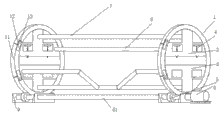
Fig. 1 is a schematic perspective view of the present invention.
The specific embodiment
As shown in Figure 1, the present invention includes the circular frame 1 that two peripheries are provided with track, be provided with lower supporting frame 2,3 in the said circular frame 1, said upward lower supporting frame 2,3 is symmetricly set in the both sides up and down of the central horizontal section of circular frame 1.Upper support frame 2 is provided with the puller bolt 4 to lower supporting frame 3 directions.The below of two circular frames 1 is provided with the rail wheel 5 with its periphery roller-way coupling, and said rail wheel 5 is provided with Power Drive Unit 6 (in the present embodiment, Power Drive Unit is a motor).
Still as shown in Figure 1; Be provided with tie-beam between two circular frames 1, said tie-beam is provided with two groups, and every group is provided with two; Girder 7 in every group is symmetricly set in the circular frame 1 limit portion in lower supporting frame 2,3 outsides, and its downward projection is perpendicular to bearing support 1/2nd places.Auxiliary girder 8 in every group is arranged at the circular frame 1 limit portion of girder 7 the same sides, and is provided with 45 degree angles between the girder 7.Wherein one group auxiliary girder approximate mid-section position is the disconnection shape, and the length of breaking off breach is roughly 1/5th (when being convenient to lift vehicle frame, through the hoist cable of purlin car) of auxiliary girder length.
Still as shown in Figure 1, frame 11 two ends of the circular frame 1 between last lower supporting frame 2,3 one ends are connected in adjacent frame through jockey.Said jockey is provided with clamping plate 12 for this section frame 11 two ends, and clamping plate 12 are sandwiched in adjacent frame end, and clamping plate 12 and adjacent frame end are provided with connecting hole, runs through said hole with pin or bolt 13 and connects.
Still as shown in Figure 1, the rail wheel 5 that is arranged at two circular frame 1 belows respectively is movably connected on the base 9 through axle 51, and the output shaft of wheel shaft 51 and Power Drive Unit 6 that is positioned at the rail wheel 5 of circular frame 1 the same side connects firmly.
Carry out vehicle frame when welding, unclamp bolt 13, open frame 11, with the supreme lower supporting frame of vehicle frame handling to be welded 2, between 3 and be placed on the lower supporting frame, hold out against, can weld with puller bolt 4 with crane.After vehicle frame top welded, starter motor, rail wheel rotated and drive circular frame 1 rotation, and vehicle frame is done arbitrarily angled upset welding in the 360 degree scopes.The operator can stand in and carry out welding operation on the auxiliary girder.
Claims (7)
1. automobile frame welding tooling is characterized in that: comprise that two peripheries are provided with the circular frame of track, be provided with lower supporting frame in the said circular frame, saidly go up the both sides up and down that lower supporting frame is symmetricly set in the central horizontal section of circular frame; Be provided with tie-beam between two circular frames, the below of two circular frames is provided with the rail wheel with its periphery roller-way coupling, and said rail wheel is provided with Power Drive Unit.
2. a kind of automobile frame welding tooling as claimed in claim 1, it is characterized in that: the upper support frame is provided with the puller bolt to the lower supporting frame direction.
3. a kind of automobile frame welding tooling as claimed in claim 1; It is characterized in that: said tie-beam is provided with two groups; Every group is provided with two, and the girder in every group is symmetricly set in the circular frame limit portion in the lower supporting frame outside, and its downward projection is perpendicular to bearing support 1/2nd places;
Auxiliary girder in every group is arranged at the circular frame limit portion of girder the same side, and is provided with 30-60 degree angle between the girder.
4. a kind of automobile frame welding tooling as claimed in claim 3 is characterized in that: wherein one group auxiliary girder approximate mid-section position is the disconnection shape, and the length of breaking off breach is roughly 1/5th of auxiliary girder length.
5. a kind of automobile frame welding tooling as claimed in claim 1 is characterized in that: the frame two ends of the circular frame between two bearing support one ends are connected in adjacent frame through jockey.
6. a kind of automobile frame welding tooling as claimed in claim 5; It is characterized in that: said jockey is provided with clamping plate for this section frame two ends; Clamping plate are sandwiched in adjacent frame end, and clamping plate and adjacent frame end are provided with connecting hole, connect with pin or the said hole of bolt-through.
7. a kind of automobile frame welding tooling as claimed in claim 1; It is characterized in that: the rail wheel that is arranged at two circular frames below respectively is movably connected on the base through axle, and the wheel shaft and the output shaft of Power Drive Unit that are positioned at the rail wheel of circular frame the same side connect firmly.
Priority Applications (1)
| Application Number | Priority Date | Filing Date | Title |
|---|---|---|---|
| CN2012100701286A CN102672383A (en) | 2012-03-16 | 2012-03-16 | Automobile frame welding tool |
Applications Claiming Priority (1)
| Application Number | Priority Date | Filing Date | Title |
|---|---|---|---|
| CN2012100701286A CN102672383A (en) | 2012-03-16 | 2012-03-16 | Automobile frame welding tool |
Publications (1)
| Publication Number | Publication Date |
|---|---|
| CN102672383A true CN102672383A (en) | 2012-09-19 |
Family
ID=46805291
Family Applications (1)
| Application Number | Title | Priority Date | Filing Date |
|---|---|---|---|
| CN2012100701286A Pending CN102672383A (en) | 2012-03-16 | 2012-03-16 | Automobile frame welding tool |
Country Status (1)
| Country | Link |
|---|---|
| CN (1) | CN102672383A (en) |
Cited By (4)
| Publication number | Priority date | Publication date | Assignee | Title |
|---|---|---|---|---|
| CN102825417A (en) * | 2012-09-27 | 2012-12-19 | 无锡久一重工机械有限公司 | Standard knot welding power-driven fixture |
| CN103302436A (en) * | 2013-06-13 | 2013-09-18 | 无锡国电华新起重运输设备有限公司 | Clamp for unidirectionally positioning web |
| CN103949840A (en) * | 2014-04-28 | 2014-07-30 | 湖南合力兴邦机械有限公司 | Frame turning device |
| CN104097012A (en) * | 2013-04-11 | 2014-10-15 | 南通中集顺达集装箱有限公司 | Turnover frame |
-
2012
- 2012-03-16 CN CN2012100701286A patent/CN102672383A/en active Pending
Cited By (5)
| Publication number | Priority date | Publication date | Assignee | Title |
|---|---|---|---|---|
| CN102825417A (en) * | 2012-09-27 | 2012-12-19 | 无锡久一重工机械有限公司 | Standard knot welding power-driven fixture |
| CN104097012A (en) * | 2013-04-11 | 2014-10-15 | 南通中集顺达集装箱有限公司 | Turnover frame |
| CN104097012B (en) * | 2013-04-11 | 2015-12-23 | 南通中集顺达集装箱有限公司 | Rollover stand |
| CN103302436A (en) * | 2013-06-13 | 2013-09-18 | 无锡国电华新起重运输设备有限公司 | Clamp for unidirectionally positioning web |
| CN103949840A (en) * | 2014-04-28 | 2014-07-30 | 湖南合力兴邦机械有限公司 | Frame turning device |
Similar Documents
| Publication | Publication Date | Title |
|---|---|---|
| CN102381383B (en) | Turning device for assembling tires of heavy duty cars | |
| CN202243777U (en) | Overturning device for assembling heavy-type automobile tires | |
| CN102672383A (en) | Automobile frame welding tool | |
| CN102009305B (en) | Frame assembly production line and use method thereof | |
| CN103663129B (en) | Passenger vehicle axle shell half-shell special hanger | |
| CN202556005U (en) | Welding tooling for automobile frame | |
| CN107350699B (en) | Welding, transferring, overturning and shifting device and method for overturning and welding box beam | |
| CN107297593B (en) | A kind of application method of Trailer type frame for use in vehicle parts assembling welding system | |
| CN113084415A (en) | H-shaped steel bracket welding system | |
| CN202571696U (en) | Oscillating anti-deformation welding clamping apparatus for bridge plate unit | |
| CN208391301U (en) | A kind of strong production line of Two bors d's oeuveres weldering | |
| CN202754616U (en) | Butt weld rebar transmission power assisting device | |
| CN203566175U (en) | Turnover device of railway tank car | |
| CN216178037U (en) | Overturning fixture tool for bogie frame of railway vehicle | |
| CN214988152U (en) | Wheel pair steering device for railway vehicle | |
| CN210655085U (en) | Turnover equipment | |
| CN213614869U (en) | Special welding set of automobile body steel construction | |
| CN201042756Y (en) | Crane main girder turnover machine | |
| CN203471239U (en) | Auxiliary welding device for cargo boom of tower crane | |
| CN207205701U (en) | A kind of steel containment vessel head plate turning device | |
| CN207003520U (en) | A kind of quick-replaceable quartering hammer support | |
| CN106181199B (en) | Track train underframe group is to tire | |
| CN104070321A (en) | Assembly welding conversion device for locomotive end part beam | |
| CN204957663U (en) | Railcar is transported to steel sheet | |
| CN212600043U (en) | Automobile pipe clamp assembling tool |
Legal Events
| Date | Code | Title | Description |
|---|---|---|---|
| C06 | Publication | ||
| PB01 | Publication | ||
| C02 | Deemed withdrawal of patent application after publication (patent law 2001) | ||
| WD01 | Invention patent application deemed withdrawn after publication |
Application publication date: 20120919 |