CN102615519A - Vacuum imbibition clamp and method for processing composite material with clamp - Google Patents
Vacuum imbibition clamp and method for processing composite material with clamp Download PDFInfo
- Publication number
- CN102615519A CN102615519A CN2012100892743A CN201210089274A CN102615519A CN 102615519 A CN102615519 A CN 102615519A CN 2012100892743 A CN2012100892743 A CN 2012100892743A CN 201210089274 A CN201210089274 A CN 201210089274A CN 102615519 A CN102615519 A CN 102615519A
- Authority
- CN
- China
- Prior art keywords
- workpiece
- vacuum
- clamp
- piezo
- anchor clamps
- Prior art date
- Legal status (The legal status is an assumption and is not a legal conclusion. Google has not performed a legal analysis and makes no representation as to the accuracy of the status listed.)
- Granted
Links
Images


Landscapes
- Jigs For Machine Tools (AREA)
Abstract
The invention provides a vacuum imbibition clamp and a method for processing a composite material with the clamp. The vacuum imbibition clamp comprises a clamp body, a vacuum sucking disk, a vacuum duct, a positioning mechanism and a piezoelectric crystal inching mechanism, wherein the vacuum sucking disk is used for clamping a workpiece, and is arranged on the top surface of the clamp body; the vacuum duct is formed inside the clamp body; one end of the vacuum duct is connected with the vacuum sucking disk, and the other end of the vacuum duct is connected with a vacuum generator; the positioning mechanism is used for limiting the movement and rotation of the workpiece, and is arranged on the side face of the clamp body; the piezoelectric crystal inching mechanism is used for supporting the workpiece and ensuring needed tension force output; and a linear movement output component of the piezoelectric crystal inching mechanism is arranged on the side face of the clamp body. Due to the adoption of the vacuum imbibition clamp and the method, the problems of insufficient rigidity and vibration in a workpiece machining process can be solved, the workpiece is prevented from deforming, the processing precision is increased, and the surface quality is improved.
Description
Technical field
The present invention relates to composite precision cutting processing technique field, the method that relates in particular to a kind of vacuum imbibition anchor clamps and use these anchor clamps processing work under condition of high speed milling.
Background technology
Composite has that density is little, strength and stiffness are high, heatproof, wear-resisting, characteristics such as fatigue resistance good, damping capacity good, anti-ablation, radioresistance, transducing and other physical functions; Whereby, composite is widely used in fields such as building, communications and transportation, chemical industry, boats and ships, Aero-Space and universal machines.
Composite is a kind of typical difficult-to-machine material, and its bad machining property has caused high processing charges, and working (machining) efficiency is low to make its commercialized degree fail to reach people's desired value far away, therefore needs the high-efficiency machining method of research composite badly.High-speed milling is a kind of important means of composite processing, and the precision optical machinery processing request that it can better satisfy complexity Noodles composite material parts has higher crudy and working (machining) efficiency.High-speed milling can keep splendid surface geometry precision, can guarantee the surface of good roughness again, and does not exist because the instrument decrease of hardness that cutting temperature rises and causes can prolong life tools significantly, has characteristics rapidly and efficiently simultaneously again.
Thin wall component because of its compact conformation, in light weight, consumptive material is few, cost is low etc., and characteristics are widely used.But because poor rigidity, the weak strength of thin-walled parts; In the high-speed milling process; By the distortion that the effect of clamp power and Milling Force load very easily produces machining deformation, part morpheme error is increased, influence the surface precision of workpiece and be difficult for the crudy of assurance part.Secondly, vibration problem directly influences the surface roughness of workpiece.And the diversity of composite has determined it to have diversified mechanical behavior characteristic, and its processing technology, machining condition and clamping method (holding method) have different with traditional metal material more.With the comb core material is example: cutting technique has emery cutter cutting, high-pressure water jet cutting, cut, High-speed NC Machining technology etc.; Mostly clamping method is bonding fixing, and like polyethylene glycol method, double-sided adhesive tape method, vacuum suction method etc., bond effect is not good and follow-up cleaning difficulty is big.But the location and the clamping device of the composite material thin wall spare of present non-structure advantages of simple still, enforcement economy are to improve the machining accuracy and the surface quality of thin-walled parts.
Summary of the invention
The object of the present invention is to provide a kind of vacuum imbibition anchor clamps and use the method for this anchor clamps machining composite material,, improve machining accuracy and surface quality to solve the not enough problem with vibration of rigidity in the thin-wall part process.
In order to realize the object of the invention, vacuum imbibition anchor clamps provided by the invention comprise chuck body; Vacuum cup is used for the fixing workpiece, and is located at the end face of said chuck body; The vacuum duct, it is inner to be located at said chuck body, and an end links to each other with said vacuum cup, and the other end is used for being connected with vacuum generator; Detent mechanism is used to limit workpiece and moves and rotate, and is located at the side of said chuck body; The piezo-electric crystal micromotion mechanism is used for supporting workpiece and guarantees required expanding force output, and the rectilinear motion output block of said piezo-electric crystal micromotion mechanism is located at the side of said chuck body.
In order to realize the object of the invention, the method for the above-mentioned vacuum imbibition of use provided by the invention anchor clamps machining composite material may further comprise the steps: step 1, set up the three-dimensional CAD physical model of workpiece; The planning cutter path generates the CAM program, machining simulation process, and sophisticated model; Step 2, in main stressed and deformed region, confirm the position of the crucial anchor point of workpiece, and optimize distribution, installing and locating mechanism on two walls of anchor clamps, fixation workpiece position; Step 3, according to the composite type of workpiece, estimate total cutting force size, confirm structure, the form of vacuum cup, confirm the mounting means of vacuum size and vacuum cup; Step 4, workpiece is installed on the anchor clamps, to the workpiece location, vacuum sucks; Piezoelectric stack is applied voltage; Two walls of piezo-electric crystal micromotion mechanism top tight workpiece, fast detecting and diagnosis clamp and the tensioner process is confirmed; The processing beginning, the process of clamped condition and monitoring of tensioner abnormal state and processing is until process finishing.
The present invention is used for the high-speed milling fine finishining stage of composite material work piece complex profile; Can guarantee that clamp force distribution is even; Solve rigidity deficiency and the problem of vibrating in the workpiece process, thereby avoid workpiece to clamp distortion, raising machining accuracy and surface quality.
Description of drawings
Fig. 1 is the structural representation of the preferred embodiment of vacuum imbibition anchor clamps of the present invention;
Fig. 2 is the chuck body structural representation of preferred embodiment shown in Figure 1.
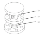
Fig. 3 is the structural representation of the piezo-electric crystal micromotion mechanism of preferred embodiment shown in Figure 1.
The specific embodiment
Below in conjunction with the accompanying drawing and the specific embodiment the present invention is explained further details.
Fig. 1 and Fig. 2 Fig. 3 schematically show the structure of the preferred embodiment of vacuum imbibition anchor clamps of the present invention; As shown in the figure, this preferred embodiment comprises end face 4, vacuum duct 5, detent mechanism and the piezo-electric crystal micromotion mechanism 13 of clamp mount 1, chuck body 3, chuck body 3.Clamp mount 1 end face is provided with the locating surface 2 that is used to locate workpiece to be machined; The end face 4 of chuck body 3 is provided with vacuum cup 5 chuck body 3 set inside has vacuum duct 6; Vacuum duct 6 one ends link to each other with vacuum cup 5; The other end is used for being connected with the vacuum generators that are arranged at chuck body 3 outsides, and vacuum generator then is connected in air supply system.
In this preferred embodiment, chuck body 3 is cube structure like Fig. 2, and its wall is installed two detent mechanisms and two piezo-electric crystal micromotion mechanisms respectively.Detent mechanism comprises locating piece 7,8 and 9.Through locating piece 7, locating piece 8 and locating piece 9 fixation workpiece positions, restriction workpiece X, the Y direction moves and the rotation of Z direction.The inverse piezoelectric effect that has through piezo-electric crystal realizes that accurate displacement control guarantees required expanding force output simultaneously, makes tensioner top board 10, the 11 direct supporting workpieces of piezo-electric crystal micromotion mechanism 13.
As shown in Figure 3, piezo-electric crystal micromotion mechanism 13 comprises tensioner top board 10 and 11, piezoelectric stack 12 and flexible hinge 14.Piezoelectric stack 12 provides tensioner required driving force.When piezoelectric stack 12 was applied voltage, tensioner top board 10,11 Precision Linear Moving in the direction made the workpiece tensioner.Piezo-electric crystal micromotion mechanism 13 is provided with flexible hinge 14; Flexible hinge 14 is convex shape; Its with chuck body 3 on hold piezo-electric crystal micromotion mechanism 13 hole wall contact, receive piezoelectric stack 12 driving force effects and when relative motion took place, corresponding torsional deflection took place flexible hinge 14; Cancel piezoelectric stack 12 driving forces and do the time spent, flexible hinge 14 is got back to initial position.
For better application preferred embodiment shown in Figure 1, the present invention also provides a kind of method of using the processing thin-walled workpiece of above-mentioned vacuum imbibition anchor clamps, may further comprise the steps,
Modeling and analysis: three-dimensional CAD (Computer Aided Design, the CAD) physical model of setting up workpiece; The planning cutter path generates CAM (computer Aided Manufacturing, computer-aided manufacturing) program, machining simulation process, and sophisticated model; Extract the processing profile, carry out the stressed finite element analysis with distortion of workpiece in the high-speed milling process, improve once more and revise model according to cutter path.
Workpiece location:, in main stressed and deformed region, confirm the position of the crucial anchor point of workpiece to be machined, and optimize distribution, installing and locating pin on two walls of clamp body, fixation workpiece position according to The results.
Vacuum cup is set: according to the composite type of workpiece to be machined, estimate total cutting force size, confirm structure, the form of vacuum cup, confirm the mounting means of vacuum size and vacuum cup.
Processing: workpiece to be machined is installed on the anchor clamps; To the workpiece location, vacuum sucks, and makes two walls of swelling device top tight workpiece again through the electrostriction of piezo-electric stack through manual; Fast detecting and diagnosis; Clamping and tensioner process are confirmed, the processing beginning, and the process that clamped condition and tensioner abnormal state are monitored and handled is until process finishing.Wherein, piezoelectric stack 12 is controlled accurate actuation element, and when piezoelectric stack 12 was applied voltage, tensioner top board 10,11 is Precision Linear Moving in the direction.When respectively two each and every one piezoelectric stacks 12 being applied voltage, the two drives corresponding tensioner top board 10,11 tensioner workpiece respectively.Flexible hinge 14 is fixed in piezo-electric crystal micromotion mechanism 13, receives piezoelectric stack 12 driving force effects and when relative motion took place, corresponding torsional deflection took place flexible hinge 14, cancels piezoelectric stack 12 driving forces and does the time spent, and flexible hinge is got back to initial position.
In sum, vacuum imbibition anchor clamps of the present invention are used for the high-speed milling fine finishining stage of thin-wall workpiece complex profile, one one mould; Can guarantee that clamp force distribution is even, avoid clamping distortion, solve rigidity deficiency and vibration problem in the workpiece process; Improve machining accuracy and surface quality; Can reduce the distortion of workpiece in process, reduce vibration, thereby improve surface precision and surface roughness after the processing; The raising of vacuum imbibition anchor clamps installed surface rigidity makes the rigidity of manufacturing process system be improved, behind process parameter optimizing; Can adopt higher cutting speed; Reduce the cutting region temperature, thereby further improve working (machining) efficiency and tool life, cut down finished cost.
Can know that by technological general knowledge the present invention can realize through other the embodiment that does not break away from its spirit or essential feature.Therefore, above-mentioned disclosed embodiment with regard to each side, all just illustrates, and is not only.All within the scope of the present invention or the change in being equal to scope of the present invention all comprised by the present invention.
Claims (5)
1. vacuum imbibition anchor clamps comprise chuck body, it is characterized in that, also comprise:
Vacuum cup is used for the fixing workpiece, and is located at the end face of said chuck body;
The vacuum duct, it is inner to be located at said chuck body, and an end links to each other with said vacuum cup, and the other end is used for being connected with vacuum generator;
Detent mechanism is used to limit workpiece and moves and rotate, and is located at the side of said chuck body;
The piezo-electric crystal micromotion mechanism is used for supporting workpiece and guarantees required expanding force output, and the rectilinear motion output block of said piezo-electric crystal micromotion mechanism is located at the side of said chuck body.
2. vacuum imbibition anchor clamps according to claim 1 is characterized in that said detent mechanism is a locating piece.
3. vacuum imbibition anchor clamps according to claim 1 is characterized in that, said piezo-electric crystal micromotion mechanism comprises:
The tensioner top board is located at the end of said piezo-electric crystal micromotion mechanism, is used for direct supporting workpiece;
Piezoelectric stack is located in the said piezo-electric crystal micromotion mechanism, and being used to utilize inverse piezoelectric effect is that said tension mechanism provides driving force;
Flexible hinge is convex, is located on the said piezo-electric crystal micromotion mechanism, and directly contacts with said chuck body, is used for making said tensioner top board be reset to initial position as the time spent cancelling said piezoelectric stack driving force.
4. a method of using the arbitrary described vacuum imbibition anchor clamps machining composite material of claim 1-3 is characterized in that, may further comprise the steps:
Step 1, set up the three-dimensional CAD physical model of workpiece; The planning cutter path generates the CAM program, machining simulation process, and sophisticated model;
Step 2, in main stressed and deformed region, confirm the position of the crucial anchor point of workpiece, and optimize distribution, installing and locating mechanism on two walls of anchor clamps, fixation workpiece position;
Step 3, according to the composite type of workpiece, estimate total cutting force size, confirm structure, the form of vacuum cup, confirm the mounting means of vacuum size and vacuum cup;
Step 4, workpiece is installed on the anchor clamps, to the workpiece location, vacuum sucks; Piezoelectric stack is applied voltage; Two walls of piezo-electric crystal micromotion mechanism top tight workpiece, fast detecting and diagnosis clamp and the tensioner process is confirmed; The processing beginning, the process of clamped condition and monitoring of tensioner abnormal state and processing is until process finishing.
5. method according to claim 4 is characterized in that, in step 1, also comprises and extracts the processing profile after the sophisticated model, and carry out the stressed finite element analysis with distortion of workpiece in the high-speed milling process according to cutter path, improves once more and revises model.
Priority Applications (1)
| Application Number | Priority Date | Filing Date | Title |
|---|---|---|---|
| CN2012100892743A CN102615519B (en) | 2012-03-30 | 2012-03-30 | Vacuum imbibition clamp and method for processing composite material with clamp |
Applications Claiming Priority (1)
| Application Number | Priority Date | Filing Date | Title |
|---|---|---|---|
| CN2012100892743A CN102615519B (en) | 2012-03-30 | 2012-03-30 | Vacuum imbibition clamp and method for processing composite material with clamp |
Publications (2)
| Publication Number | Publication Date |
|---|---|
| CN102615519A true CN102615519A (en) | 2012-08-01 |
| CN102615519B CN102615519B (en) | 2013-11-13 |
Family
ID=46555908
Family Applications (1)
| Application Number | Title | Priority Date | Filing Date |
|---|---|---|---|
| CN2012100892743A Expired - Fee Related CN102615519B (en) | 2012-03-30 | 2012-03-30 | Vacuum imbibition clamp and method for processing composite material with clamp |
Country Status (1)
| Country | Link |
|---|---|
| CN (1) | CN102615519B (en) |
Cited By (7)
| Publication number | Priority date | Publication date | Assignee | Title |
|---|---|---|---|---|
| CN103495890A (en) * | 2013-10-14 | 2014-01-08 | 集美大学 | Rapid clamping device used for side milling and drilling of carbon fiber thin board |
| CN104001973A (en) * | 2014-05-08 | 2014-08-27 | 中航飞机股份有限公司西安飞机分公司 | Processing method for honeycomb core |
| CN104369013A (en) * | 2014-10-29 | 2015-02-25 | 苏州市金德誉精密机械有限公司 | Box punching clamp table |
| CN105364575A (en) * | 2015-12-04 | 2016-03-02 | 苏州明远冲压件厂 | Three-direction fixing and punching clamp table |
| CN106312460A (en) * | 2016-09-27 | 2017-01-11 | 北京航天新风机械设备有限责任公司 | Processing method of carbon fiber magnesium-based composite thin plate with flatness being less than 0.2mm |
| CN107414223A (en) * | 2017-09-12 | 2017-12-01 | 苏州沃思诺自动化科技有限公司 | A kind of resetting tool for thin-wall workpiece |
| CN108705351A (en) * | 2018-06-29 | 2018-10-26 | 江西佳时特数控技术有限公司 | Scroll plate flexible production line Moving plate vortex face processing tool |
Citations (5)
| Publication number | Priority date | Publication date | Assignee | Title |
|---|---|---|---|---|
| DE102005050649A1 (en) * | 2005-10-20 | 2007-04-26 | Deutsche Solar Ag | Apparatus and method for fixing non-ferrous metal blocks |
| CN101518875A (en) * | 2008-11-24 | 2009-09-02 | 中国航天科技集团公司长征机械厂 | Precision positioning and clamping device of lathe |
| KR20090102568A (en) * | 2008-03-26 | 2009-09-30 | 이부락 | Ceramic ball panel type air vacuum tight |
| CN201455680U (en) * | 2009-04-14 | 2010-05-12 | 武汉理工大学 | Ultraprecise micro-feed tool holder |
| CN201769068U (en) * | 2010-09-07 | 2011-03-23 | 苏州工业园区艺达精密机械有限公司 | Workpiece clamping device |
-
2012
- 2012-03-30 CN CN2012100892743A patent/CN102615519B/en not_active Expired - Fee Related
Patent Citations (5)
| Publication number | Priority date | Publication date | Assignee | Title |
|---|---|---|---|---|
| DE102005050649A1 (en) * | 2005-10-20 | 2007-04-26 | Deutsche Solar Ag | Apparatus and method for fixing non-ferrous metal blocks |
| KR20090102568A (en) * | 2008-03-26 | 2009-09-30 | 이부락 | Ceramic ball panel type air vacuum tight |
| CN101518875A (en) * | 2008-11-24 | 2009-09-02 | 中国航天科技集团公司长征机械厂 | Precision positioning and clamping device of lathe |
| CN201455680U (en) * | 2009-04-14 | 2010-05-12 | 武汉理工大学 | Ultraprecise micro-feed tool holder |
| CN201769068U (en) * | 2010-09-07 | 2011-03-23 | 苏州工业园区艺达精密机械有限公司 | Workpiece clamping device |
Non-Patent Citations (2)
| Title |
|---|
| 汪欢等: "风扇盘铣圆弧槽夹具的设计", 《中国新技术新产品》 * |
| 赵运航等: "环形薄壁件加工中的胀紧减振夹具设计", 《中国新技术新产品》 * |
Cited By (9)
| Publication number | Priority date | Publication date | Assignee | Title |
|---|---|---|---|---|
| CN103495890A (en) * | 2013-10-14 | 2014-01-08 | 集美大学 | Rapid clamping device used for side milling and drilling of carbon fiber thin board |
| CN103495890B (en) * | 2013-10-14 | 2016-01-20 | 集美大学 | For the quick clamping device of carbon fiber sheet side milling and boring |
| CN104001973A (en) * | 2014-05-08 | 2014-08-27 | 中航飞机股份有限公司西安飞机分公司 | Processing method for honeycomb core |
| CN104369013A (en) * | 2014-10-29 | 2015-02-25 | 苏州市金德誉精密机械有限公司 | Box punching clamp table |
| CN105364575A (en) * | 2015-12-04 | 2016-03-02 | 苏州明远冲压件厂 | Three-direction fixing and punching clamp table |
| CN106312460A (en) * | 2016-09-27 | 2017-01-11 | 北京航天新风机械设备有限责任公司 | Processing method of carbon fiber magnesium-based composite thin plate with flatness being less than 0.2mm |
| CN106312460B (en) * | 2016-09-27 | 2018-05-11 | 北京航天新风机械设备有限责任公司 | Flatness is less than the carbon fiber magnesium-based composite material thin plate processing method of 0.2mm |
| CN107414223A (en) * | 2017-09-12 | 2017-12-01 | 苏州沃思诺自动化科技有限公司 | A kind of resetting tool for thin-wall workpiece |
| CN108705351A (en) * | 2018-06-29 | 2018-10-26 | 江西佳时特数控技术有限公司 | Scroll plate flexible production line Moving plate vortex face processing tool |
Also Published As
| Publication number | Publication date |
|---|---|
| CN102615519B (en) | 2013-11-13 |
Similar Documents
| Publication | Publication Date | Title |
|---|---|---|
| CN102615519B (en) | Vacuum imbibition clamp and method for processing composite material with clamp | |
| Wei et al. | Design of a new passive end-effector based on constant-force mechanism for robotic polishing | |
| CN102615520A (en) | Composite material thin-walled piece clamp and method for processing composite material by using clamp | |
| Chen et al. | Robot machining: recent development and future research issues | |
| Gameros et al. | State-of-the-art in fixture systems for the manufacture and assembly of rigid components: A review | |
| CN105563309B (en) | It is a kind of actively to comply with end effector and its control method for adjustable pitch propeller robot grinding | |
| CN102179708B (en) | Multipoint profiling rigid clamp and method for processing thin-wall workpiece by using same | |
| EP2103376B1 (en) | Cutting device for vibration cutting | |
| CN110153781B (en) | Thin-wall part machining vibration suppression device and method based on bending actuator | |
| Sato et al. | Analysis of the coupled vibration between feed drive systems and machine tool structure | |
| CN103302522A (en) | Workpiece clamping jig and workpiece machining method using workpiece clamping jig | |
| Tian et al. | A novel long range fast tool servo for diamond turning | |
| Chen et al. | Design philosophy of an ultra-precision fly cutting machine tool for KDP crystal machining and its implementation on the structure design | |
| Yi et al. | Error compensation of thin plate-shape part with prebending method in face milling | |
| CN113059464A (en) | Constant-force polishing mechanism and polishing equipment | |
| CN108788628B (en) | Processing method of curved surface CD texture | |
| Davim | Mechatronics | |
| CN113334137A (en) | Three-dimensional ultrasonic vibration machining tool and control method thereof | |
| US8453545B2 (en) | Machine tool and machining method thereof | |
| CN112264852A (en) | Double-arm robot cooperative vibration damping method for polishing large thin-walled workpiece | |
| CN106926037B (en) | Clamp suitable for complex curved surface machining and use method thereof | |
| Park et al. | Gantry type lapping manipulator toward unmanned lapping process for a large work surface | |
| Wei et al. | Design of a new robot end-effector based on compliant constant-force mechanism | |
| JP2004345017A (en) | Method and device for grooving | |
| Sawada et al. | Development of ultraprecision machining center with closed-loop structure and its control |
Legal Events
| Date | Code | Title | Description |
|---|---|---|---|
| C06 | Publication | ||
| PB01 | Publication | ||
| C10 | Entry into substantive examination | ||
| SE01 | Entry into force of request for substantive examination | ||
| C14 | Grant of patent or utility model | ||
| GR01 | Patent grant | ||
| CF01 | Termination of patent right due to non-payment of annual fee |
Granted publication date: 20131113 Termination date: 20190330 |
|
| CF01 | Termination of patent right due to non-payment of annual fee |