CN102510973B - Lamp with base members, socket apparatus, and illumination appliance - Google Patents
Lamp with base members, socket apparatus, and illumination appliance Download PDFInfo
- Publication number
- CN102510973B CN102510973B CN2011800038906A CN201180003890A CN102510973B CN 102510973 B CN102510973 B CN 102510973B CN 2011800038906 A CN2011800038906 A CN 2011800038906A CN 201180003890 A CN201180003890 A CN 201180003890A CN 102510973 B CN102510973 B CN 102510973B
- Authority
- CN
- China
- Prior art keywords
- lamp
- socket
- power supply
- base device
- signal
- Prior art date
- Legal status (The legal status is an assumption and is not a legal conclusion. Google has not performed a legal analysis and makes no representation as to the accuracy of the status listed.)
- Active
Links
Images


Classifications
-
- F—MECHANICAL ENGINEERING; LIGHTING; HEATING; WEAPONS; BLASTING
- F21—LIGHTING
- F21S—NON-PORTABLE LIGHTING DEVICES; SYSTEMS THEREOF; VEHICLE LIGHTING DEVICES SPECIALLY ADAPTED FOR VEHICLE EXTERIORS
- F21S8/00—Lighting devices intended for fixed installation
- F21S8/02—Lighting devices intended for fixed installation of recess-mounted type, e.g. downlighters
-
- F—MECHANICAL ENGINEERING; LIGHTING; HEATING; WEAPONS; BLASTING
- F21—LIGHTING
- F21V—FUNCTIONAL FEATURES OR DETAILS OF LIGHTING DEVICES OR SYSTEMS THEREOF; STRUCTURAL COMBINATIONS OF LIGHTING DEVICES WITH OTHER ARTICLES, NOT OTHERWISE PROVIDED FOR
- F21V29/00—Protecting lighting devices from thermal damage; Cooling or heating arrangements specially adapted for lighting devices or systems
- F21V29/50—Cooling arrangements
- F21V29/70—Cooling arrangements characterised by passive heat-dissipating elements, e.g. heat-sinks
-
- F—MECHANICAL ENGINEERING; LIGHTING; HEATING; WEAPONS; BLASTING
- F21—LIGHTING
- F21K—NON-ELECTRIC LIGHT SOURCES USING LUMINESCENCE; LIGHT SOURCES USING ELECTROCHEMILUMINESCENCE; LIGHT SOURCES USING CHARGES OF COMBUSTIBLE MATERIAL; LIGHT SOURCES USING SEMICONDUCTOR DEVICES AS LIGHT-GENERATING ELEMENTS; LIGHT SOURCES NOT OTHERWISE PROVIDED FOR
- F21K9/00—Light sources using semiconductor devices as light-generating elements, e.g. using light-emitting diodes [LED] or lasers
- F21K9/20—Light sources comprising attachment means
-
- F—MECHANICAL ENGINEERING; LIGHTING; HEATING; WEAPONS; BLASTING
- F21—LIGHTING
- F21V—FUNCTIONAL FEATURES OR DETAILS OF LIGHTING DEVICES OR SYSTEMS THEREOF; STRUCTURAL COMBINATIONS OF LIGHTING DEVICES WITH OTHER ARTICLES, NOT OTHERWISE PROVIDED FOR
- F21V19/00—Fastening of light sources or lamp holders
- F21V19/0005—Fastening of light sources or lamp holders of sources having contact pins, wires or blades, e.g. pinch sealed lamp
-
- F—MECHANICAL ENGINEERING; LIGHTING; HEATING; WEAPONS; BLASTING
- F21—LIGHTING
- F21V—FUNCTIONAL FEATURES OR DETAILS OF LIGHTING DEVICES OR SYSTEMS THEREOF; STRUCTURAL COMBINATIONS OF LIGHTING DEVICES WITH OTHER ARTICLES, NOT OTHERWISE PROVIDED FOR
- F21V23/00—Arrangement of electric circuit elements in or on lighting devices
- F21V23/003—Arrangement of electric circuit elements in or on lighting devices the elements being electronics drivers or controllers for operating the light source, e.g. for a LED array
- F21V23/004—Arrangement of electric circuit elements in or on lighting devices the elements being electronics drivers or controllers for operating the light source, e.g. for a LED array arranged on a substrate, e.g. a printed circuit board
- F21V23/006—Arrangement of electric circuit elements in or on lighting devices the elements being electronics drivers or controllers for operating the light source, e.g. for a LED array arranged on a substrate, e.g. a printed circuit board the substrate being distinct from the light source holder
-
- F—MECHANICAL ENGINEERING; LIGHTING; HEATING; WEAPONS; BLASTING
- F21—LIGHTING
- F21V—FUNCTIONAL FEATURES OR DETAILS OF LIGHTING DEVICES OR SYSTEMS THEREOF; STRUCTURAL COMBINATIONS OF LIGHTING DEVICES WITH OTHER ARTICLES, NOT OTHERWISE PROVIDED FOR
- F21V23/00—Arrangement of electric circuit elements in or on lighting devices
- F21V23/003—Arrangement of electric circuit elements in or on lighting devices the elements being electronics drivers or controllers for operating the light source, e.g. for a LED array
- F21V23/007—Arrangement of electric circuit elements in or on lighting devices the elements being electronics drivers or controllers for operating the light source, e.g. for a LED array enclosed in a casing
- F21V23/009—Arrangement of electric circuit elements in or on lighting devices the elements being electronics drivers or controllers for operating the light source, e.g. for a LED array enclosed in a casing the casing being inside the housing of the lighting device
-
- F—MECHANICAL ENGINEERING; LIGHTING; HEATING; WEAPONS; BLASTING
- F21—LIGHTING
- F21V—FUNCTIONAL FEATURES OR DETAILS OF LIGHTING DEVICES OR SYSTEMS THEREOF; STRUCTURAL COMBINATIONS OF LIGHTING DEVICES WITH OTHER ARTICLES, NOT OTHERWISE PROVIDED FOR
- F21V15/00—Protecting lighting devices from damage
- F21V15/01—Housings, e.g. material or assembling of housing parts
-
- F—MECHANICAL ENGINEERING; LIGHTING; HEATING; WEAPONS; BLASTING
- F21—LIGHTING
- F21V—FUNCTIONAL FEATURES OR DETAILS OF LIGHTING DEVICES OR SYSTEMS THEREOF; STRUCTURAL COMBINATIONS OF LIGHTING DEVICES WITH OTHER ARTICLES, NOT OTHERWISE PROVIDED FOR
- F21V21/00—Supporting, suspending, or attaching arrangements for lighting devices; Hand grips
- F21V21/02—Wall, ceiling, or floor bases; Fixing pendants or arms to the bases
- F21V21/04—Recessed bases
-
- F—MECHANICAL ENGINEERING; LIGHTING; HEATING; WEAPONS; BLASTING
- F21—LIGHTING
- F21V—FUNCTIONAL FEATURES OR DETAILS OF LIGHTING DEVICES OR SYSTEMS THEREOF; STRUCTURAL COMBINATIONS OF LIGHTING DEVICES WITH OTHER ARTICLES, NOT OTHERWISE PROVIDED FOR
- F21V29/00—Protecting lighting devices from thermal damage; Cooling or heating arrangements specially adapted for lighting devices or systems
- F21V29/50—Cooling arrangements
- F21V29/70—Cooling arrangements characterised by passive heat-dissipating elements, e.g. heat-sinks
- F21V29/74—Cooling arrangements characterised by passive heat-dissipating elements, e.g. heat-sinks with fins or blades
- F21V29/77—Cooling arrangements characterised by passive heat-dissipating elements, e.g. heat-sinks with fins or blades with essentially identical diverging planar fins or blades, e.g. with fan-like or star-like cross-section
- F21V29/773—Cooling arrangements characterised by passive heat-dissipating elements, e.g. heat-sinks with fins or blades with essentially identical diverging planar fins or blades, e.g. with fan-like or star-like cross-section the planes containing the fins or blades having the direction of the light emitting axis
-
- F—MECHANICAL ENGINEERING; LIGHTING; HEATING; WEAPONS; BLASTING
- F21—LIGHTING
- F21V—FUNCTIONAL FEATURES OR DETAILS OF LIGHTING DEVICES OR SYSTEMS THEREOF; STRUCTURAL COMBINATIONS OF LIGHTING DEVICES WITH OTHER ARTICLES, NOT OTHERWISE PROVIDED FOR
- F21V29/00—Protecting lighting devices from thermal damage; Cooling or heating arrangements specially adapted for lighting devices or systems
- F21V29/85—Protecting lighting devices from thermal damage; Cooling or heating arrangements specially adapted for lighting devices or systems characterised by the material
- F21V29/89—Metals
-
- F—MECHANICAL ENGINEERING; LIGHTING; HEATING; WEAPONS; BLASTING
- F21—LIGHTING
- F21Y—INDEXING SCHEME ASSOCIATED WITH SUBCLASSES F21K, F21L, F21S and F21V, RELATING TO THE FORM OR THE KIND OF THE LIGHT SOURCES OR OF THE COLOUR OF THE LIGHT EMITTED
- F21Y2115/00—Light-generating elements of semiconductor light sources
- F21Y2115/10—Light-emitting diodes [LED]
Abstract
Provided is a lamp with base members, a socket apparatus, and an illumination appliance, wherein influence by noise is reduced. The lamp with base members is provided with: a lamp body comprising latching means that are to be mounted onto a socket apparatus detachably,a light-emitting unit housed within the lamp body,a control device housed within the lamp body, and which is for controlling the turning on of a light-emitting unit,power-supply base-members that are positioned adjacent to each other at one side of a latching means, arranged on a trajectory of a circle of the lamp-body, and connected to the control device,signal base-members that are positioned adjacent to each other at the other side of the latching means, arranged on a trajectory of the circle of the lamp-body, and connected to the control device,and a heat conductor that comes in contact with a heat dissipator when in a state of being mounted onto the socket apparatus.
Description
Technical field
Embodiments of the present invention relate to a kind of can be corresponding to lamp (lamp), lamp socket (socket) device and the ligthing paraphernalia of the attached socket of the control of light modulation etc.
Background technology
In the past, showcase (show case) was used with lamp etc. under illumination or frame, the compact fluorescent lamp (fluorescent lamp) that is suitable for the smooth thin type structure of narrow space.In recent years, light emitting diode (the Light Emitting Diode of the attached socket of smooth thin type structure has been proposed, LED) lamp to be to replace described fluorescent lamp, the LED lamp of the attached socket of described smooth thin type structure adopted long and little power consumption of life-span solid-state light emitting element, be that light emitting diode is used as light source.
The prior art document
Patent documentation
Patent documentation 1: Japanese Patent Laid-Open 2010-129488 communique
The summary of invention
The technical problem that invention institute wish solves
This kind LED lamp generally comprises the socket of GX53 shape, but in the mode of removable, this kind LED lamp is installed on the lamp base device that can connect described socket, thereby forms ligthing paraphernalia.On the other hand, for this kind LED lamp, needing can be corresponding to lamp and the lamp base device of the attached socket of the control of light modulation etc., and problem is:, in order stably to carry out described control, how to make holding wire not be vulnerable to impact from the noise (noise) of the power line that is connected in lamp base device.Simultaneously, problem is: as how hindering lamp and lamp base device, the mode of the miniaturization of ligthing paraphernalia even, the laying of described power line or holding wire is simplified.
Summary of the invention
The present invention is the invention that forms in view of described problem, the object of the present invention is to provide: the lamp, lamp base device and the ligthing paraphernalia that make the attached socket that the impact of noise reduces.
The lamp of the attached socket of an embodiment of the invention comprise have the engaging unit the lamp body, but this engaging unit removable be installed on lamp base device, illuminating part is housed in the lamp body.The illuminating part control device of controlling of lighting a lamp is housed in the lamp body.The power supply that is connected in control device is positioned at the position adjacent with the side across engaging unit with the socket member, and is provided on the track of circle of lamp body.The signal that is connected in control device is positioned at the position adjacent with another side across engaging unit with the socket member, and is provided on the circumferencial direction of lamp body.And the lamp of described attached socket comprises heat carrier, and this heat carrier, being installed under the state of lamp base device, comes in contact with radiator.
In addition, lamp base device in an embodiment of the invention comprises: the lamp socket body with engaging unit, but the lamp of attached socket is installed this engaging unit removable, the power supply that is connecting the lamp of attached socket is positioned at terminal component with the power supply of socket member: the position adjacent with the side across engaging unit, and be provided on the circumferencial direction of lamp socket body.The signal that is connecting the lamp of attached socket is positioned at terminal component with the signal of socket member: the position adjacent with another side across engaging unit, and be provided on the track of circle of lamp socket body.
The effect of invention
, according to an embodiment of the invention, can provide lamp, lamp base device and the ligthing paraphernalia of the attached socket of the impact minimizing that makes noise.
Description of drawings
Fig. 1 represents that embodiments of the present invention are the lamp of attached socket, and Fig. 1 (a) is stereogram, and Fig. 1 (b) is the sectional stereogram along the b-b line of Fig. 2, and Fig. 1 (c) is taken out signal and the profile that represents with the socket member.
Fig. 2 is removed outer cover component to represent the top view of the lamp of attached socket.
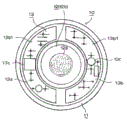
Fig. 3 is the bottom view of the lamp of attached socket equally.
Fig. 4 is the circuit blocks figure of the control device in the lamp of attached socket equally.
The same indication lamp base device of Fig. 5, Fig. 5 (a) is front view, Fig. 5 (b) is side view.
The same indication lamp base device of Fig. 6, Fig. 6 (a) are from the being seen stereogram of face side, and Fig. 6 (b) is the front view that represents enlargedly to engage unit.
Fig. 7 observes being seen stereogram from rear side to lamp base device.
Fig. 8 is the figure of the state of the work of the lamp of the attached socket of model utility ground expression and the engaging unit in lamp base device and supporting member and electric connection equally, Fig. 8 (a) means the figure of the state that the engaging unit has engaged, and Fig. 8 (b) means the figure of the state that the engaging unit does not engage.
Terminal board in the same indication lamp base device of Fig. 9, Fig. 9 (a) mean that terminal board has been contained in the stereogram of the state of terminal shell, and Fig. 9 (b) is the stereogram of terminal board.
Figure 10 means the stereogram that the lamp of attached socket is installed on the state of lamp base device equally.
The same expression of Figure 11 is installed on the lamp of attached socket the state of lamp base device, and Figure 11 (a) is the exterior view of lamp base device, and Figure 11 (b) is the back view of socket member.
The same expression of Figure 12 is installed on the lamp of attached socket the ligthing paraphernalia that lamp base device forms, Figure 12 (a) means the profile that Down lamp is arranged at the state of ceiling, and Figure 12 (b) is with the lamp of the attached socket of Figure 12 (a) and the sectional stereogram that lamp base device is cut off to represent.
The variation of the lamp of the attached socket of the same expression of Figure 13, Figure 13 (a) means the profile that is equivalent to Fig. 1 (b) of the first variation, Figure 13 (b) means the profile that is equivalent to Fig. 2 of the first variation.
The variation of the lamp of the attached socket of the same expression of Figure 14, Figure 14 (a) means the profile that is equivalent to Fig. 1 (b) of the second variation, Figure 14 (b) means the profile that is equivalent to Fig. 1 (b) of the 3rd variation.
Figure 15 represents the variation of ligthing paraphernalia equally, and Figure 15 (a) is top view, and Figure 15 (b) is the profile along the A-line of Figure 15 (a).
The specific embodiment
Reference numeral
10: the lamp of attached socket
11: the lamp body
11f: engaging unit
11e: protuberance
11g: heat carrier
12: illuminating part
13: control device
14: power supply socket member
15: signal socket member
20: lamp base device
21: the lamp socket body
21a1: engaging unit
22: the power supply terminal component
23: the signal terminal component
30: ligthing paraphernalia
34: radiator
Below, the embodiment of lamp, lamp base device and the ligthing paraphernalia of attached socket is described.
At first, the formation of the lamp of attached socket described.The lamp of the attached socket of present embodiment constitutes: the lamp 10 of attached socket of smooth thin type structure that is provided with the socket member of pin shape, and as shown in Figure 1 to 4, comprise: lamp body 11, have engaging unit 11f, but this engaging unit 11f by rotating operation and removable be installed on lamp base device; Illuminating part 12, be housed in the lamp body; Control device 13, to being housed in the control of lighting a lamp of the intrinsic illuminating part of lamp; Power supply, with socket member 14, is positioned at the position adjacent with the side across engaging unit, is provided on the circumferencial direction of lamp body, and is connected in control device 13; And signal socket member 15, be positioned at the position adjacent with another side across engaging unit, be provided on the circumferencial direction of lamp body, and be connected in control device 13.
For thermal diffusivity is improved, lamp body 11 comprises the good metal of thermal conductivity, comprise in the present embodiment aluminium, and the flat shape in cross section is the dish of circular, and the 11b of base plate supports section that comprises recessed section circular section is integrally formed in the peristome 11a of an end side.The bottom surface of recessed section section of base plate supports section forms smooth face, forms around convex strip portions 11c in the form of a ring.In addition, the other end side of lamp body 11 is to form the mode of the 11d of supporting section section of ring-type at outer bottom, to form the columned protuberance 11e that inside is made as cancave embedded part.The 11g of the thermal conductive surface as heat carrier in the formed present embodiment of the outer bottom of protuberance 11e forms smooth face, and then hot adherence and be supported in the radiator 34 of utensil side.Whereby, lamp body 11 comprises protuberance 11e, and this protuberance 11e is outstanding with the middle body that socket member 15 surrounds with socket member 14 and signal from power supply described later, and is installed on lamp base device 21.The radiator 34 of utensil side contacts with the end face formation face of the protuberance 11e that is installed on lamp base device 21.
In addition, the outstanding size of described protuberance 11e forms greatlyr than the hole depth size of the supported hole 21a of lamp socket body 21 described later, and when lamp body 11 was installed on lamp socket body 21, the thermal conductive surface 11g of the end face of protuberance 11e was outstanding from supported hole 21a.Moreover, the conducting strip of polysilicone etc. is positioned on the plane of thermal conductive surface 11g of end face of protuberance 11e, whereby, radiating effect is improved, the conducting strip of described polysilicone etc. carries out heat to the heat from LED well in order to efficiency and conducts.
Form engaging unit 11f on the outer peripheral face of protuberance 11e.But the engaging unit be in order to removable be installed on the unit of engaging unit 21a1 set on lamp base device 20 described later, in the present embodiment, make engaging protrusion protrude from integratedly the outer peripheral face of protuberance 11e, form whereby the engaging unit (below, the engaging unit 11f of the lamp of attached socket is called " engaging protrusion 11f ") of the lamp 10 of attached socket.
As shown in Figure 3, from lamp body 11De center o,, towards diametric(al), have on the outer peripheral face of protuberance 11e of angle of 120 °, separate impartial interval and be formed with 3 engaging protrusion 11f, each engaging protrusion 11f is roughly foursquare identical shape.For example, utilize casting, forging or machining etc. to process the lamp body 11 of described formation.In the present embodiment, utilize aluminium casting (aluminum cast) to form described lamp body 11.
Utilize the good metal of thermal conductivity to form substrate 12b, in the present embodiment, utilize flat thin circle and be tabular aluminium and form substrate 12b, on the surface of this substrate 12b (upper surface in Fig. 1 (b)), across the electric insulation layer of polysilicone etc. and be formed with the Wiring pattern (pattern) that comprises Copper Foil, 6 LED 12a, roughly to be the mode of concentric circles, roughly equally spaced set and are assemblied in (Fig. 2) on described Wiring pattern.Whereby, form the illuminating part 12 comprise light emitting module (module), 6 LED 12a of this illuminating part 12 roughly are point-symmetric mode with the center with respect to circular substrate, and are configured in circle and are on tabular substrate 12b.
Mode take the formed base plate supports 11b of section of end side with body 11 as electric insulation and adherence, and set the illuminating part 12 that forms in this way.In addition, as required, across (not shown) such as electric insulation sheets that comprise polysilicone etc., and use the fixed cell 12c of screw etc., described illuminating part 12 adherences ground are fixed in the bottom surface of the 11b of base plate supports section of the face that is smooth.
Whereby, illuminating part 12 is contained in an end side of lamp body 11, and the positively adherence of the back side of substrate 12b is in the 11b of base plate supports section of lamp body 11, utilize the good aluminium of thermal conductivity to form substrate 12b, the heat that therefore, can LED12a be produced conducts to the lamp body 11 that comprises aluminium and dispels the heat with producing effect.According to described formation, comprise the optical axis y-y of illuminating part 12 of the substrate 12b that is equipped with 6 LED12a and the central shaft x-x of lamp body 11 and roughly coincide, and the light source portion that is constructed as follows, this light source portion comprises: be roughly on the whole circular light-emitting area when overlooking.
As shown in the circuit blocks figure of Fig. 4, control device 13 comprises: lamp circuit 13a the alternating voltage of 100V is converted to the DC voltage of 24V, and the DC current that will determine electric current is supplied to LED12a; And, control circuit 13b, according to the control signal from outside make that illuminating part 12 is lit a lamp, extinguished, light modulation, toning etc., light a lamp in the present embodiment, extinguish, light modulation.As shown in Fig. 1 (b), the electronic component 13c that forms described lamp circuit 13a and control circuit 13b is the circuit substrate 13d that is assemblied in circular flat glass epoxide compound (glass epoxy) system.Circuit substrate 13d is formed with circuit pattern on single face or two faces, a plurality of small-sized electronic component 13c are the fitting surfaces that are assemblied in this circuit substrate 13d, and are housed in lamp body 11.
Moreover in the present embodiment, described electronic component 13c is housed in lamp body 11 in such a way.That is, be accompanied by the part of heating, for example switching transistor (switching transistor) 13c1 separates because of wire (lead wire) and circuit substrate 13d, and adherence be contained in the inner bottom surface of lamp body 11.In addition, larger wire part, for example current transformer (current transformer) 13c2 is housed in the formed cancave embedded part of protuberance 11e by the lamp body.Whereby, the heat that is accompanied by the switching transistor 13c1 of heating is released into outside from the lamp body 11 that comprises aluminium, makes temperature rise and is suppressed.Simultaneously, it is in cancave embedded part that large part is housed in protuberance 11e, forms the smooth thin type structure of lamp body 11.
The circuit substrate 13d that forms in this way is via the plastic feet 13e with heat resistance and electric insulating quality, in this example via PETG (Polybutylene Terephthalate, PBT) the feet 13e of system, below with the substrate 12b that is in illuminating part 12, and separate the mode at the interval of regulation with the inner bottom surface of lamp body, and set and be supported in lamp body 11.In Fig. 1 (b), 13f is thermal insulation board, this thermal insulation board 13f utilizes having heat resistance, electric insulating quality and having the synthetic resin of thermal insulation and form discoideus of PBT etc., this thermal insulation board 13f is supported in the upper face center section of circuit substrate 13d in the gapped mode of tool, and between the substrate 12b and circuit substrate 13d of illuminating part 12, whereby, the heat affecting each other between substrate 12b and circuit substrate 13d is blocked.Moreover, by wire (not shown) will form the circuit substrate 13d of control device 13 lead-out terminal, be connected with the input terminal of the substrate 12b of illuminating part 12.
In addition, lamp circuit 13a and control circuit 13b form in the mode shown in the circuit blocks figure of Fig. 4.Namely, lamp circuit 13a comprises: AC/DC converter (Alternating Current/Direct current converter, AC/DC converter), rectification circuit or determine current supply circuit etc., and the alternating voltage of the 100V of source power supply E is converted to the DC voltage of 24V, with the DC current that will determine electric current, be supplied to each LED12a.Control circuit 13b comprises: microcomputer (microcomputer) etc., and, based on the control signal of coming from external transmission, produce in order to light a lamp, to extinguish, to reach the control signal of light modulation, and this control signal is supplied to lamp circuit 13a.This lamp circuit 13a is the control of lighting a lamp in such a way, that is, based on described control signal, the LED12a of illuminating part 12 lit a lamp, extinguish, reach light modulation.Moreover, about the control signal of coming from external transmission, in the present embodiment, the light modulator 37 of the set existing incandescent lamp bulbs such as wall in room being used by the user operates, whereby, described control signal transfers to control circuit 13b via holding wire S1.In figure 14 is in order to be connected in the power supply socket member of source power supply via lamp base device 20, the 15th, in order to via lamp base device 20 with the signal that control signal is inputted socket member.
In addition, control device 13 in present embodiment comprises: signal socket member 15, this signal with socket member 15 in order to will input to from the control signal of the light modulator 37 of outside the input side of control circuit 13b, lamp circuit 13a and control circuit 13b are connected in power supply in parallel, even holding wire is not connected in signal socket member 15, described lamp circuit 13a and control circuit 13b still can work.Therefore, in the situation that light modulator 37 is not set, the lamp that can make described attached socket is worked as the lamp of the common attached socket that does not have dimming function.
As shown in Fig. 1 (b), power supply comprises the metal with electric conductivity of copper or brass etc. with socket member 14, comprise in the present embodiment brass, this power supply forms with a pair of socket pin of socket member 14 by pin shape, and a pair of socket pin of this pin shape comprises: cylindrical axial region 14a and discoideus basal part 14b.Described power supply is to imbed integratedly and be supported in supporting substrate 14c by ester moulding with socket member 14, and this supporting substrate 14c utilizes the synthetic resin with heat resistance and electric insulating quality of PBT etc. and forms discoideus.Be prepared to 2 right supporting substrate 14c that imbed integratedly power supply use socket member 14, the a pair of supported hole 11d1 of the circle that described 2 supporting substrate 14c is embedded in respectively in the 11d of supporting section section of ring-type of lamp body 11, forms with the side of engaging protrusion 11f adjacently, and utilize the bonding agent that comprises polysilicone or epoxy resin etc. to be fixed.
Whereby, as shown in Figure 3, a pair of power supply with socket member 14-1,14-2 is positioned at the engaging protrusion 11f-2 of lamp 10 across attached socket, namely engage adjacent position, a side of unit, and be provided on the track of circle of lamp body 11.And power supply arranges to foreign side from the outer bottom of lamp body 11 highlightedly with a pair of columned axial region 14a of socket member 14, and each basal part 14b is electrically connected at control device 13 by wire w1.Moreover, power supply socket member 14 according to present embodiment, as shown in the chain-dotted line in Fig. 1 (b), the leading section of the axial region 14a of pin shape is not outstanding from lamp body 11, therefore, because the caused external impact such as falling, the risk (risk) that the socket pin deforms is reduced, thereby can make, fault is installed reduces, this installations fault is to be out of shape the installation fault of the lamp with attached socket that causes while being installed on lamp base device by socket.Moreover,, about this formation, also form in the same way signal described later with socket member 15, can make the fault minimizing is installed.
As shown in Fig. 1 (c), signal has with socket member 15: with described power supply with the identical shape of socket member 14, size and comprise copper or the metal with electric conductivity of brass etc., comprise in the present embodiment brass, this signal forms with a pair of socket pin of socket member 15 by pin shape, and a pair of socket pin of this pin shape comprises: cylindrical axial region 15a and discoideus basal part 15b.Described signal is to imbed integratedly and be supported in supporting substrate 15c by ester moulding with socket member 15, and this supporting substrate 15c utilizes the synthetic resin with heat resistance and electric insulating quality of PBT etc. and forms discoideus.Be prepared to 2 right supporting substrate 15c that imbed integratedly signal use socket member 15, the a pair of supported hole 11d1 of the circle that described 2 supporting substrate 15c is embedded in respectively in the 11d of supporting section section of ring-type of lamp body 11, forms with another side of engaging protrusion 11f adjacently, and utilize the bonding agent that comprises polysilicone or epoxy resin etc. to be fixed.
Whereby, as shown in Figure 3, a pair of signal with socket member 15-1,15-2 is positioned at the engaging protrusion 11f-2 of lamp 10 across attached socket, namely engage adjacent position, another side of unit, and be provided on the track of circle of lamp body 11.In addition, be equipped with signal with the track of the circle of socket member 15 be provided in the track of power supply with the identical circle of the track of the circle of socket member 14 on, can not hinder miniaturization.Moreover, also can be in the scope that does not hinder miniaturization, with described be equipped with signal with the track of the circle of socket member 15 be provided in from the track of power supply with the different circle of the track of the circle of socket member 14 on.And signal arranges to foreign side from the outer bottom of lamp body 11 highlightedly with a pair of columned axial region 15a of socket member 15, and each basal part 15b is electrically connected at control device 13 by wire (not shown).
According to described content, as shown in Figure 3, described power supply with socket member 14 and signal with socket member 15 across engaging protrusion 11f-2 (engaging unit), separate each other two sides at engaging protrusion 11f-2 with the size of regulation, and be positioned at adjacent position, and be provided on the track of circle of lamp body 11.Whereby, can make wire w1 that power supply is connected with control device 13 with socket member 14, and wire that signal is connected with control device 13 with socket member 15, concentrate on a position of two sides of engaging protrusion 11f-1, and the laying of power line or holding wire can be simplified, thereby can realize the miniaturization of the lamp 10 of attached socket.
And when power supply was positioned in opposite directions position on diametric(al) with socket member 14 and signal with socket member 15, each electric wire was laid in the position of separation that must be on diametric(al), in addition, need to be at each electric wire of the interior tractive of lamp body 11, therefore, the space (space) that needs tractive to use.Therefore, wiring operation complicates, and is difficult to realize the miniaturization of lamp body.
And, simultaneously, because power supply uses socket member 15 across engaging protrusion 11f-2 with socket member 14 and signal, separate each other the position in two sides of engaging protrusion 11f-2 with the size of regulation, the noise that the wire that therefore, wire that signal uses or socket member 15 are difficult to receive easily use from power supply or socket member 14 produce.
Power supply in present embodiment is used the Angular Dimension of socket member 15 and 3 engaging protrusion 11f with socket member 14, signal, that is, the Angular Dimension of lamp 10 sides of attached socket is to set in such a way.namely, as shown in the bottom view of the lamp 10 of the attached socket of Fig. 3, if utilize the center o from 2 engaging protrusion 11f-1 in engaging protrusion 11f and engaging protrusion 11f-2 as starting point to represent towards diametric angle, towards a power supply that is adjacent to engaging protrusion 11f-1, with the diametric angle θ 1 of socket member 14-1, it is 45 °, be 95 ° towards another (another that separate with engaging protrusion 11f-1) power supply with the diametric angle θ 2 of socket member 14-2, 2 engaging protrusion 11f-1 in described engaging protrusion 11f and engaging protrusion 11f-2 form across the interval of equalization with the angle of 120 °.
In addition, be 45 ° towards a signal that is adjacent to engaging protrusion 11f-2 with the diametric angle θ 1 of socket member 15-1, another (another that separate with engaging protrusion 11f-2) signal is 95 ° with socket member 15-2 angulation θ 2 on diametric(al).
Moreover, each angle θ 1 and angle θ 2 are line a-a and line b-b angulation, described line a-a is the central axis by each engaging protrusion 11f, and described line b-b uses socket member 14 and signal with separately cylindrical axial region 14a of socket member 15, the axle center of 15a by power supply.In addition, the α of the angle of rotation with respect to lamp base device 20 1 of the lamp 10 of attached socket is 15 °.Moreover, the diameter of cylindrical axial region 14a, 15a
 Be about 2.5mm, the outstanding size h1 of counting from the 11d of supporting section section of
 lamp body 11 is about 6mm, and the outside diameter d 1 of cancave embedded part 11e is about 65mm.Allow the increase and decrease to some extent in the scope of foozle of described angle and size.Moreover in described content, a pair of power supply also can be opposite with the position relationship of socket member 15 with socket member 14 and a pair of signal.
Then, as shown in Figure 1, outer cover (cover) member 16 forms the lampshade (globe) of lamp, and comprise: have the transparent member of light transmission or have the translucent member of light diffusing, comprise in the present embodiment milky glass, this outer cover (cover) member 16 forms: at one end section's side is provided with the flat curve form of peristome 16a.The edge that peristome 16a is surrounded is to become side wall portion 16b cylindraceous, and with described peristome front in opposite directions, forms level and smooth curved surface shape.The outer cover component 16 that forms in this way gives in a covered manner and opposite to each other and arranging with the illuminating part 12 with lamp body 11, peristome 16a is embedded in the inner surface of convex strip portions 11c of an end side of lamp body 11 with the lap of regulation, then with the bonding agent of polysilicone or epoxy resin etc., is fixed.According to described content, form the lamp 10 of the attached socket of smooth thin type structure, the lamp 10 of the attached socket of this smooth thin type structure is at the illuminating part 12 that an end side of lamp body 11 is provided with outer cover component 16 and comprises LED12a, the power supply that is provided with pin shape in the other end side with socket member 14 and signal with socket member 15.
Then, the formation of lamp base device described.The lamp base device of present embodiment is the lamp base device that is constructed as follows, the power supply of pin shape of lamp 10 that this lamp base device is being electrically connected described attached socket with socket member 14 and signal with socket member 15, and be loaded to ligthing paraphernalia 30 and be used, as Fig. 5~shown in Figure 10, described lamp base device comprises: lamp socket body 21, have engaging unit 21a1, but the lamp 10 of attached socket by rotating operation and removable be installed on this engaging unit 21a1; Power supply with terminal component 22, is positioned at the position adjacent with the side across engage unit, is provided on the track of circle of lamp socket body 21, and is connecting the power supply use socket member 14 of the lamp 10 of attached socket; And signal with terminal component 23, is positioned at the position adjacent with another side across engage unit, is provided on the track of circle of lamp socket body 21, and is connecting the signal use socket member 15 of the lamp 10 of attached socket.
In addition,, in the face side (upper surface in Fig. 6) of lamp socket body 21, make the peripheral part of flange shape ringwise face erect integratedly and form sidewall 21f.This sidewall is to prevent the wall that shocks by electricity, and with can not make one-sided axial region be inserted into lamp base device each terminal component mode and form, described electric shock is to use axial region 14a, the 15a of the one-sided pin shape of socket member 15 with socket member 14 or signal because of the power supply of the lamp 10 of attached socket described later, and the power supply that mistake is inserted into lamp base device 20 produces with terminal component 23 with terminal component 22 or signal.In the present embodiment, socket member 14,15 outstanding size h1 form approximately 6mm, and the height h4 of sidewall forms approximately 5mm.
In addition,, at the inner peripheral surface of supported hole 21a, form the engaging unit 21a1 of lamp base device 20.The engaging unit is following unit, this unit is together with the engaging unit 11f of the lamp 10 with attached socket, by rotating operation and but removable ground is installed on lamp base device 20 with the lamp of attached socket 10, in the present embodiment, slot 21a1 is integrally formed in the inner peripheral surface of supported hole 21a, form whereby the engaging unit (below, the engaging unit 21a1 of lamp base device is called " slot 21a1 ") of lamp base device 20.
As shown in Figure 5,, from lamp socket body 21De center o to diametric(al), have on the inner peripheral surface of supported hole 21a of angle of 120 °, separate impartial interval and be formed with 3 identical shaped slot 21a1.As shown in Fig. 6 (b), each slot 21a1 comprises: insertion section 21a2, and the end face that is included in supported hole 21a forms the pod of opening; Holding section 21a3, comprise with insertion section conjointly and the translot that forms along general horizontal direction (rotation direction of lamp body 10); And locking protrusion 21a4, be formed on the bight of the boundary line below that becomes the insertion section 21a1 that is the L font and holding section 21a3, in other words, is formed on the part of the entrance that becomes slot 21a1 and is chevron.Moreover, the engaging protrusion 11f of the lamp body 11 that inserts from insertion section 21a2 simultaneously slides and is connected to the locking protrusion 21a4 that is chevron, one side is guided, after crossing the summit of chevron, be directed in the 21a3 of holding section, as described below, prevent half suspension by the locking protrusion 21a4 that is chevron, and make in engaging and the time can unexpectedly not come off.
In addition, rear side (lower surface in Fig. 6 (a)) at lamp socket body 21 is provided with supporting member 21b, this supporting member 21b, in order to lamp socket body 21 is supported in the section of being set up, in the present embodiment, is supported in lamp socket body 21 radiator 34 of ligthing paraphernalia 30 described later.From lamp socket body 21De center o to diametric(al), at the lower surface with the angle of 120 ° and lamp socket body 21 in the form of a ring, separate impartial interval and be formed with 3 described supporting member 21b, 2 supporting member 21b wherein are arranged on the position close to described slot 21a1.Each supporting member 21b is identical shape, and as shown in Figure 8, each supporting member 21b comprises: tubular cylinder (cylinder) 21b1; Be inserted into bolt (bolt) 21b2 in cylinder; And, inserted logical helical spring (coil spring) 21b3 by bolt.
Cylinder 21b1 founds the rear side of the flange shape in the form of a ring face of establishing and be formed at lamp socket body 21 integratedly by ester moulding.End plate 12a4 is limited to the open end of the upper surface of cylinder 21b1.The leading section of bolt 21b2 runs through described end plate, and in the mode that can move up and down in cylinder, bolt is set, and the front end of bolt is outstanding from the upper surface side of cylinder 21b1.By described bolt 21b2, lamp base device 20 being supported in the section of being set up, is the radiator 34 that is supported in ligthing paraphernalia 30 in the present embodiment.This radiator 34 side (lower surface of Fig. 8) overleaf is formed with the screw hole of using for bolt 21b2 screw-in, and bolt 21b2 screws in to described screw hole, makes lamp base device 20 be supported in the lower surface of radiator 34.
As mentioned above, the lamp base device 20 that is supported in the radiator 34 of ligthing paraphernalia 30 is installed with the lamp 10 of attached socket, whereby, utilizes the elastic force of spring 21b3, pushes the smooth thermal conductive surface 11g of the protuberance 11e of lamp body 11 to the back side of radiator 34.Namely, as shown in Fig. 8 (a), the protuberance 11e of lamp body 11 is inserted into the supported hole 21a of lamp base device 20, make the slot 21a1 of the engaging protrusion 11f aligning lamp base device 20 of lamp body 11, from insertion section 21a2, engaging protrusion 11f is inserted, then to the left in figure, rotated.Whereby, engaging protrusion 11f crosses the locking protrusion 21a4 of chevron, and is directed in the 21a3 of holding section, with the lamp 10 with attached socket, is installed on lamp base device 20.At this moment, by the lower surface of the engaging protrusion 11f of lamp body 11, (direction of the arrow a in figure) pushing lamp socket body 21 downwards, and with the rear side of radiator 34, form separatedly gap s.Simultaneously, the spring 21b3 of lamp socket body 21 is compressed because of described pushing process, by the repulsion (power of the direction of the arrow b in figure) of this spring 21b3, lamp body 11 strongly is urged to the back side of radiator 34.Whereby, comprise the smooth thermal conductive surface 11g of protuberance 11e of lamp body of aluminium and radiator 34 the hot adherence in the back side supported, the heat that can a plurality of LED12a be produced is released into outside with producing effect, thereby can use the LED of high brightness, high output.
Moreover, when the lamp 10 with attached socket is removed from lamp base device 20, as long as with described mode, rotate on the contrary lamp body 11, the engaging protrusion 11f that makes lamp body 11 moves along the holding section 21a3 of lamp base device 20, and engaging protrusion 11f is extracted out from the 21a2 of insertion section, then the protuberance 11e of lamp body 11 is extracted out and gets final product from the supported hole 21a of lamp base device 20.After lamp base device 20 was removed, as shown in Fig. 8 (b), the compression of spring 21b3 was disengaged, and is back to original position with the lamp of attached socket 10, and the upper surface of lamp socket body 21 seamlessly is supported in the rear side of radiator 34.
Then, as shown in Figure 9, the power supply that is connecting the lamp 10 of attached socket comprises with terminal component 22 with the power supply of socket member 14: be integrally formed in lamp socket body 21 little terminal shell 22a, with the terminal board 22b that is housed in terminal shell.The adjacent ground connection of the rear side of flange shape face ringwise (Fig. 7) with lamp socket body 21, be provided with pair of terminal shell 22a integratedly.Terminal board 22b is accommodated in the enclosure, and at one end section forms electric wire insertion section 22a1.
The terminal board 22b that forms in this way is embedded in terminal shell 22a in the rear side of flange shape face ringwise (Fig. 7) of lamp socket body 21, and the side of described terminal shell 22a and slot 21a1-1 is adjacent and integrally formed.Terminal shell 22a is formed and is circular-arc recess by the lamp socket body 21 along in the form of a ring to be formed, and comprises: electric wire insertion section 22a1; Form the slotted hole 22a2 of opening in the face side (Fig. 6) of lamp socket body 21; And, the lid 22a3 that the opening of rear side is stopped up.
Slotted hole 22a2 forms: has semicircular opening at two ends and is circular-arc shape, and the mode so that elongated little terminal board 22b is fallen from slotted hole, and form described slotted hole 22a2.In addition, width dimensions forms following size, and this size can be inserted for the columned axial region 14a of the power supply socket member 14 in the lamp 10 of attached socket and be mobile.In addition, lid 22a3 is stopped up the opening of the rear side of terminal shell 22a, and, at the upper surface that is positioned at electric wire insertion section 22a1 side, forms live wire guide plate 22a4.
The terminal shell 22a and the terminal board 22b that form in this way that each prepares a pair of identical formation,, in the mode towards slotted hole 22a2, be housed in each terminal board 22b in each terminal shell 22a.Then, make the opening obturation of the rear side of terminal shell 22a by lid 22a3, utilize the bonding agent that comprises polysilicone or epoxy resin etc. to be fixed.Whereby, as shown in Figure 7, a pair of power supply is positioned at terminal component 22-1,22-2: with slot 21a1-1 across lamp base device 20, namely engage adjacent position, a side of unit, and be provided on the track of circle of lamp socket body 21.
Then, with power supply, use terminal component 14 similarly, form: the signal signal terminal component 23 of socket member 15 that is connecting the lamp of attached socket.About the formation of terminal shell 23a and terminal board 23b, in Fig. 9 with signal with the symbolic representation of each constituent part in terminal component 23 in (), and omitted detailed explanation.
According to described formation, a pair of signal is positioned at terminal component 23-1,23-2: with slot 21a1-1 across lamp base device 20, namely engage adjacent position, another side of unit, and be provided on the track of circle of lamp socket body 21.In addition, be equipped with signal and with the track of the circle of terminal component 23 be: be provided in the track of power supply with the identical circle of the track of the circle of terminal component 22 on, can not hinder miniaturization.Moreover, also can be in the scope that does not hinder miniaturization, with described be equipped with signal with the track of the circle of terminal component 23 be provided in from the track of power supply with the different circle of the track of the circle of terminal component 22 on.
According to described content, as shown in Figure 7, power supply with terminal component 22 and signal with terminal component 23 across slot 21a1-1 (engaging unit), separate each other two sides at slot 21a1-1 with the size of regulation, and be positioned at adjacent position, and be provided on the track of circle of lamp socket body 21.
Power supply in present embodiment is used the Angular Dimension of terminal component 23 and 3 slot 21a1 with terminal component 22, signal, that is, the Angular Dimension of lamp base device 20 sides is to set in such a way.namely, as shown in the exterior view of the lamp base device of Fig. 5, if utilize the center o from 2 slot 21a1-1 in slot 21a1 and engaging protrusion 21a1-2 as starting point to represent towards diametric angle, the power supply towards a side who is adjacent to slot 21a1-1 is 25 ° with the diametric angle θ 3 of terminal component 22-1, power supply towards the opposing party's (with the opposing party of slot 21a1-1 separation) is 75 ° with the diametric angle θ 4 of terminal component 22-2, 2 slot 21a1-1 in described slot 21a1 and engaging protrusion 21a1-2 form across the interval of equalization with the angle of 120 °.
In addition, signal towards a side who is adjacent to slot 21a1-2 is 25 ° with the diametric angle θ 3 of terminal component 23-1, towards the opposing party's (the opposing party who separates with slot 21a1-2) signal, with the diametric angle θ 4 of terminal component 23-2, is 75 °.
Moreover, each angle θ 3 and angle θ 4 are line c-c and line d-d angulation, described line c-c is the central axis by the insertion section 21a2 of slot 21a1, and described line d-d uses terminal component 22 and the signal center with each semi-circular portion of the inserting side (axial region 14a, the 15a of the pin shape of the lamp 10 of attached socket institute is the part of insertion at first) of terminal component 23 slotted hole 22a2,23a2 separately by power supply.In addition, the α of the angle of rotation with respect to lamp base device 20 1 of the lamp 10 of attached socket is 15 °.Moreover the internal diameter size d2 of supported hole 21a is about 65.5mm.Allow the increase and decrease to some extent in the scope of foozle of described angle and size.Moreover in described content, a pair of power supply also can be opposite with the position relationship of terminal component 23 with end member 22 and a pair of signal.
In addition, power supply is connected in the power supply terminal component 22 that forms in this way with electric wire w3, and signal is connected in signal terminal component 23 with electric wire w4.As shown in Figure 7, for power supply for electric wire w3, the power supply that is adjacent to the side of slot 21a1-1 is extracted out from electric wire insertion portion 22a1 with electric wire w3-1 with the power supply that terminal component 22-1 connects, and along the opposing party's (the opposing party who separates with slot 21a1-1) power supply with the upper surface of terminal component 22-2, be the upper surface derivation of lid 22a3, then guided by wire guide sheet 22a4, and be clamped between the sidewall of wire guide sheet 22a4 and lamp socket body 21 and prevent from coming off, and being drawn out of.In addition, the opposing party's's (with the opposing party of slot 21a1-1 separation) power supply is extracted out from electric wire insertion portion 22a1 with electric wire w3-2 with the power supply that terminal component 22-2 is connected,, with the power supply that first is drawn out of harness overlappingly up and down together with electric wire w3-1, then be drawn out of.
Described each power supply is exported with the upper surface of terminal component 22-2 along power supply with electric wire w3-1, w3-2, and by wire guide sheet 22a4 and up and down overlappingly by harness, therefore, power supply is incorporated in electric wire in the width dimensions of the rear side of flange shape face ringwise of lamp socket body 21 in the form of a ring, this power supply can not protruded from the outer peripheral face of lamp base device by compact the laying (compact) with electric wire, need not in order to hide the power supply of extracting out, the outside dimension of lamp socket body to be increased, thereby can realize the miniaturization of lamp base device 20.
Signal is similarly to be connected with electric wire w3 with power supply with electric wire w4.Namely, the signal that is adjacent to the side of slot 21a1-2 is extracted out from electric wire insertion portion 23a1 with electric wire w4-1 with the signal that terminal component 23-1 connects, and along the opposing party's (the opposing party who separates with slot 21a1-2) signal with the upper surface of terminal component 23-2, be the upper surface derivation of lid 23a3, then guided by wire guide sheet 23a4, and be clamped between the sidewall of wire guide sheet 22a4 and lamp socket body and prevent from coming off, and being drawn out of.In addition, the opposing party's's (with the opposing party of slot 21a1-2 separation) signal is extracted out from electric wire insertion portion 23a1 with electric wire w4-2 with the signal that terminal component 23-2 is connected, together with using electric wire w4-1, the signal that first is drawn out of, up and down overlappingly by harness, then is drawn out of.
Described each signal also is exported with the upper surface of terminal component 23-2 along signal with electric wire w4-1, w4-2, and by wire guide sheet 22a4 and up and down overlappingly by harness, therefore, signal is incorporated in electric wire in the width dimensions of the rear side of flange shape face ringwise of lamp socket body 21 in the form of a ring, this signal is laid compactly with electric wire and can not protruded from the outer peripheral face of lamp base device, thereby can realize the miniaturization of lamp base device 20.
Moreover, the insulating coating of the front end of each electric wire w3, w4 is peelled off, then described each electric wire w3, w4 are inserted into electric wire insertion portion 22a1, the 23a1 of each terminal shell 22a, 23a, whereby, described each electric wire w3, w4 lock and are connected in hooking sheet 22b3, the 23b3 of SL terminal.In addition, each electric wire w3 that extracts out from lamp base device 20, the terminal board 35,36 that w4 is connected in ligthing paraphernalia 30 described later.
In addition, as shown in Figure 7, use the laying of electric wire w4 with electric wire w3 and signal about described power supply, power supply with terminal component 22 and signal with terminal component 23 across slot 21a1-1 (engaging unit), separate each other two sides at slot 21a1-1 with the size of regulation, and be positioned at adjacent position, and be provided on the track of circle of lamp socket body 21.Whereby, power supply can be laid in a position of two sides of slot 21a1-1 with electric wire w4 concentrated area with electric wire w3 and signal, distribution can be simplified, thereby can realize the miniaturization of the lamp 10 of attached socket.
And when power supply was positioned in opposite directions position on diametric(al) with terminal component 22 and signal with terminal component 23, each electric wire w3, w4 were laid in the position of separation that must be on diametric(al), in addition, need to be at each electric wire of the interior tractive of lamp socket body 21, therefore, the space that needs tractive to use.Therefore, wiring operation complicates, and is difficult to realize the miniaturization of lamp socket body.
Simultaneously, due to power supply with terminal component 22 and signal with terminal component 23 across slot 21a1-1 (engaging unit), separate each other the position in two sides of slot 21a1-1 with the size of regulation, therefore, can make signal be difficult to receive with electric wire w4 or signal the noise that easily from power supply, with electric wire w3 or power supply, with terminal component 23, produces with terminal component 22.
As mentioned above, form power supply terminal component 22 and signal terminal component 23, whereby, as shown in figure 10, the protuberance 11e of the lamp of attached socket 10 is inserted in the supported hole 21a of lamp base device 20, as shown in figure 11, centered by the central point o of lamp socket body 21, the lamp 10 that makes attached socket is to the direction of arrow rotational angle α 1 in figure, in the present embodiment, rotates the angle of 15 ° to the direction of arrow in figure.Whereby, the power supply of the lamp 10 of attached socket inserts and moves to terminal board 22b from power supply with the slotted hole 22a2 of terminal component 22 with socket member 14, and simultaneously, signal inserts and move to terminal board 23b from signal with the slotted hole 23a2 of terminal component 23 with socket member 15.Then, as shown in Figure 8, power supply with socket member 14 and signal with the columned axial region 14a of socket member 15, terminal plate 22b1, the 23b1 that 15a is inserted into respectively bifurcated, then stop at the contact site 22b2 of " ㄑ " word toward each other of crossing terminal board, the position of 23b2, under this state, contact site 22b2, the 23b2 of the both sides of axial region 14a, 15a and bifurcated all come in contact, and power supply unit and signal section form electric connection simultaneously.As shown in Fig. 8 (a), the engaging protrusion 11f butt of lamp body 11 and be sticked in the end of the holding section 21a3 of the slot 21a1 in lamp socket body 21, whereby, form described contact position.
According to described content, when lamp 10 and the lamp base device 20 of attached socket formed electric connection, the lamp 10 of attached socket mechanically remained in lamp base device 20, that is, the lamp 10 of attached socket is installed on lamp base device 20.At this moment, but for lamp 10 removables with attached socket be installed on lamp base device 20, make engaging unit (engaging protrusion 11f and slot 21a1) as described below with the relation that is electrically connected, whereby, half suspension status while avoiding the lamp of attached socket 10 is installed on lamp base device 20.
Namely, as shown in Fig. 8 (a), after engaging protrusion 11f crosses the locking protrusion 21a4 of chevron of slot 21a1, form and be electrically connected, namely, power supply comes in contact with axial region 14a and the terminal board 22b of socket member 14, and signal comes in contact with axial region 15a and the terminal board 23b of socket member 15.Therefore, the user is in the way of carrying out rotating operation, and when engaging protrusion 11f crossed locking protrusion 21a4, rotating operation can be subject to resistance, so the user likely can take for and engage and the operation that stops operating.Yet at this moment, owing to not yet forming and being electrically connected, therefore, lamp can not lit a lamp.Therefore, the user will appreciate that engaging not yet fully, then carries out rotating operation until last.Result is can prevent that rotating operation from stopping on the way, thereby can avoid engaging half suspension status (locking protrusion 11f crosses the locking protrusion 21a4 state before of chevron) of unit.Whereby, the lamp of attached socket 10 positively can be installed on lamp base device 20.
In addition,, due in rotating operation, can carry out smooth operation, therefore, can realize utilizing single shirtsleeve operation of touching (one touch) operation, and can avoid engaging half suspension status of unit and half contact condition of electric connection.Namely, the resistance that is born while with engaging protrusion 11f, crossing locking protrusion 21a4, and axial region 14a, 15a these two stages of resistance of being born while crossing contact site 22b2, the 23b2 of " ㄑ " word toward each other of terminal board 22b, 23b, bear the resistance in rotating operation.Therefore, the user bears described two stage resistance in the way of rotating operation, whereby, likely can take for for twice and engage and the operation that stops operating.Particularly secondary resistance is the resistance that carries out electrical contact, engage and the operation that stops operating if take for, likely can be in half contact condition ( axial region 14a, 15a cross contact site 22b2, the 23b2 state before of " ㄑ " word toward each other of terminal board 22b, 23b).
In the present embodiment, in order to prevent described situation, the secondary resistance that bears while making axial region 14a, 15a cross the contact site of " ㄑ " word toward each other, the primary resistance that bears while less than engaging protrusion 11f, crossing locking protrusion 21a4.Particularly,, in the situation that primary resistance is made as 100%, with secondary Resistance Setting, be approximately below 70%.
Whereby, in rotating operation, can easily surmount secondary resistance by the inertia of the rotatory force that contends with primary resistance and rotation, can carry out rotating operation by only bearing primary resistance, thereby realize utilizing the rotating operation of one-touch operation.Simultaneously,, owing to can easily surmounting secondary resistance, therefore, can make axial region 14a, 15a cross contact site 22b2, the 23b2 of " ㄑ " word toward each other quickly, thereby can positively avoid electrical half contact condition.
In addition, rotating operation stops because of the end that engaging protrusion 11f is connected to the holding section 21a3 of slot 21a1, when this butt, comprises the engaging protrusion 11f and the slot 21a1 collision that comprises synthetic resin of aluminium, whereby, produce the metallic sound of " click clatter ".Whereby, can utilize sound to inform that the user engages the state that unit has engaged, that is, the lamp 10 of attached socket fully is installed on the state of lamp base device 20 understandablely.
Then, the lamp 10 that comprises the attached socket that forms is in this way described with the formation of the ligthing paraphernalia of lamp base device 20.As shown in figure 12, the 30th, imbed the ligthing paraphernalia of small-sized Down lamp (down light) formula of the ceiling surface X that is arranged at shop etc., this ligthing paraphernalia comprises: apparatus body 32 has peristome 31 and is metal case shape at lower surface; Metal reflector 33, be embedded in peristome 31; And radiator 34, being arranged at the upper surface of reflector 33, the substantial middle section at radiator 34 back sides is provided with the lamp base device 20 of described formation.Reflector 33 is that the metallic plate by good metal such as stainless steel of thermal conductivity etc. forms, and the upper surface of this reflector 33 is installed on the side of radiator 34.
In addition, the power supply of extracting out from lamp base device 20 is connected in the lead-out terminal of power supply with terminal board 35 with electric wire w3, and F cable (cable) F1 that lays within doors is connected in input terminal.In addition, the signal of extracting out from lamp base device 20 is connected in the lead-out terminal of signal with terminal board 36 with electric wire w4, and holding wire S 1 is connected in input terminal.
As shown in Figure 4, the F cable is connected in source power supply E, and power supply is connected in the power supply of lamp base device 20 with after terminal component 22 with socket member 14, and power supply is supplied to the lamp 10 of attached socket with socket member 14 via power supply with terminal component 22 from power supply.In addition, holding wire S1 is connected in light modulator 37, the signal that signal is connected in lamp base device 20 with socket member 15 is with after terminal component 23, from the control signal of light modulator 37, transfers to the lamp 10 of attached socket with socket member 15 via signal with terminal component 23 from signal.Light modulator 37 is the light modulators for the incandescent lamp bulb that first has, and can be arranged at the wall in room and by the user, be operated.Moreover each electric wire w3, w4 extract out from the electric wire leadout hole 38 that is formed at radiator 34.
In the ligthing paraphernalia 30 that forms in this way, the lamp of the attached socket of smooth slim structure 10 is installed on lamp base device 20, the lamp 10 of the attached socket of described smooth slim structure is that described LED is made as light source, and the power supply that is provided with pin shape with socket member 14 and signal with socket member 15.Described installation is as shown in Figure 10, Figure 11, make attached socket lamp 10 a pair of power supply with the slotted hole 22a2 of socket member 14 and lamp base device 20 in opposite directions, make the slotted hole 23a2 of a pair of signal use socket member 15 and lamp base device 20 in opposite directions, then each axial region 14a, 15a are inserted into slotted hole 22a2,23a2.Simultaneously, make attached socket lamp 10 3 engaging protrusion 11f respectively with 3 slot 21a1 of lamp base device 20 in opposite directions, then described 3 engaging protrusion 11f are inserted into each insertion section 21a2.
At this moment, because the face side at lamp base device 20 is formed with sidewall 21f, therefore, the power supply of the lamp 10 of attached socket can not be inserted into power supply terminal component 22 or the signal terminal component 23 of lamp base device 20 with socket member 14 or signal by mistake with the one-sided pin ( axial region 14a, 15a) of socket member 15, can prevent electric shock.
Then, the lamp 10 that makes attached socket only rotates the angle of 15 ° to the direction of arrow in figure.Whereby, as shown in Fig. 8 (a), power supply is inserted into respectively terminal plate 22b 1, the 23b 1 of bifurcated with socket member 14 and signal with axial region 14a, the 15a of socket member 15, then stop at the contact site 22b2 of " ㄑ " word toward each other of crossing terminal plate, the position of 23b2, under this state, contact site 22b2, the 23b2 of the both sides of axial region 14a, 15a and bifurcated all come in contact, thereby form, are electrically connected.Simultaneously, the engaging protrusion 11f of the lamp 10 of the attached socket that the insertion section 12a2 of the slot 21a1 from lamp base device 20 inserts is the locking protrusion 21a4 that chevron was slided and be connected to one side, and one side is guided, after crossing the summit of chevron, be directed in the 21a3 of holding section, and be connected to the end of holding section 21a3.
At this moment, after engaging protrusion 11f crosses the locking protrusion 21a4 of chevron of slot 21a1, form and be electrically connected, therefore, the user is in the way of carrying out rotating operation, when engaging protrusion 11f crossed locking protrusion 21a4, rotating operation can be subject to resistance, and the user likely can take for and engage, but this moment, owing to not yet forming and being electrically connected, therefore, lamp can not lit a lamp.Therefore, the user will appreciate that for engaging not yet fully, then carries out rotating operation until last, thereby can avoid half suspension status.
In addition, after engaging protrusion 11f is connected to the end of holding section 21a3, can send the sound of " click clatter ", therefore, the lamp 10 that the user can know attached socket is sticked in lamp base device 20 fully, thereby prevents that further engaging is in half suspension status, or prevents that electrical contact is in half contact condition.Whereby, when lamp 10 and the lamp base device 20 of attached socket formed electric connection, the lamp 10 of attached socket was installed on lamp base device 20.Moreover, can by to counter-rotation, the lamp of attached socket 10 be removed from lamp base device 20.
As mentioned above, after the engaging unit is installed on lamp base device 20 with the lamp of attached socket 10, as shown in Fig. 8 (a), lower surface by the engaging protrusion 11f of lamp body 11, push lamp socket body 21 downwards, the spring 21b3 of lamp socket body 21 is compressed, by the repulsion of this spring 21b3, the smooth thermal conductive surface 11g of the columned protuberance 11e of lamp body 11 strongly is urged to the back side of radiator 34.According to described content, form and to use the lamp 10 of attached socket of smooth slim structure as the ligthing paraphernalia 30 of the Down lamp shape of light source, the lamp 10 of the attached socket of the slim structure that this is smooth is used LED as light source.
After under described state, power supply being connected, from the power supply of lamp base device 20, with terminal component 22, via the power supply of the lamp 10 of attached socket, with socket member 14, carry out supply power, and the lamp circuit 13a of control device 13 work, the DC voltage of 24V is output.This DC voltage is applied to each LED 12a from control device 13, and after described each LED 12a had been supplied to the DC current of determining electric current, whole LED lit a lamp simultaneously.The white that radiates from each LED 12a wide causes equably to the whole inner surface radiation of outer cover component 16, utilizes milky lampshade to make the light diffusion, thereby can have the illumination of the light distribution characteristic of regulation.
In addition, the user operates the light modulator 37 that is arranged at wall, whereby, control signal with socket member 15 transfers to control circuit 13b with terminal component 23 via the signal of the lamp 10 of attached socket from the signal of lamp base device 20, produce essential dim signal by control circuit, and this dim signal is supplied to lamp circuit 13a.Lamp circuit 13a one side is carried out light modulation based on described dim signal to each LED 12a, and one side is lit a lamp each LED 12a.At this moment, the lamp 10 of attached socket and lamp base device 20 are difficult to receive the noise that easily at mains side, produces, and therefore, can stablize and correct brightness adjustment control.
According to described content, make after the lamp 10 of attached socket lights a lamp, the temperature of LED 12a rises and produces heat.This heat is as shown in Fig. 1 (b), from comprising the substrate 12b of the good aluminium of thermal conductivity, conduct to direct adherence and be fixed with the 11b of base plate supports section of substrate, then conduct to the smooth thermal conductive surface 11g of the protuberance 11e of the lamp body 11 that comprises aluminium, be released into outside via radiator 34.At this moment, due to the back side of the thermal conductive surface 11g of the protuberance 11e of lamp body 11 and radiator 34 by spring 21b3 and hot adherence supported, therefore, can produce effect to external cooling.
In addition, the heat that the electronic component 13c of control device 13 produces, the heat of particularly following the switching transistor 13c1 of heating to produce, also can from adherence contain the lamp body 11 of switching transistor inner bottom surface conduct to cancave embedded part 11e, be released into outside via radiator 34 with producing effect.By described resultful thermolysis, the temperature of the electronic component 13c in the rising of the temperature of LED12a and control device 13 rises and is suppressed, and reliability is improved.
Above, according to the lamp 10 of the attached socket of present embodiment, the power supply that is connected in control device 13 is positioned at socket member 14: the position adjacent with the side across engaging unit 13f, and be provided on the track of circle of lamp body 11; The signal that is connected in control device 13 is positioned at socket member 15: the position adjacent with another side across engaging unit 13f, and be provided on the track of circle of lamp body 11, therefore, distribution can be simplified and be realized miniaturization, and can be difficult to be subject to easily the impact of the noise that produces at mains side, in addition can be corresponding to the control of light modulation etc.
In addition, lamp base device 20 according to present embodiment, the power supply that is connecting the lamp 10 of attached socket is positioned at terminal component 22 with the power supply of socket member 14: the position adjacent with the side across engaging unit 21a1, and be provided on the track of circle of lamp socket body 21; The signal that is connecting the lamp 10 of attached socket is positioned at terminal component 23 with the signal of socket member 15: the position adjacent with another side across engaging unit 21a1, and be provided on the track of circle of lamp socket body 21, therefore, distribution can be simplified and be realized miniaturization, and can be difficult to be subject to easily the impact of the noise that produces at mains side, in addition can be corresponding to the control of light modulation etc.
Above, in the present embodiment, the lamp of attached socket preferably forms the lamp of smooth thin type structure, but the shape of lamp also can constitute the lamp shape of lamp (R shape) etc. of the attached socket of the lamp (T shape) of lamp (A shape or PS shape), the lamp (G shape) of spherical attached socket, columnar attached socket of attached socket of bulb-shaped of the shape that is similar to the ordinary incandescent lamp bubble and reflection.In addition, present embodiment is not limited to the lamp of smooth thin type structure or is similar to the lamp of attached socket of the lamp shape of ordinary incandescent lamp bubble, applicable to the lamp of the attached socket that presents other various face shapings, purposes.Moreover the lamp of attached socket preferably includes: comprise the outer cover component of lampshade or outside protective covers etc., so that light diffusion or protection illuminating part, but this for example also can form the lamp without the attached socket of lampshade not for the necessary condition of the purpose in order to realize present embodiment.
In addition, for the lamp of attached socket,, for the heat that each LED is produced is discharged with more producing effect, also illuminating part 12 can be loaded to the protuberance 11e of lamp body 11.That is, as shown in figure 13, with illuminating part 12 adherences be arranged in protuberance 11e, that is, be arranged to adherence the inner bottom surface of cancave embedded part 11e1, described protuberance 11e is used the inside of lamp body 11 as cancave embedded part 11e1.As mentioned above, illuminating part comprises: the substrate 12b of aluminum be assemblied in a plurality of LED 12a of substrate, across electric insulation sheet, and adherence ground is fixed in the inner bottom surface of cancave embedded part 11e1 with the rear side of substrate 12b.
In addition, control device 13 is divided into: form lamp circuit 13a lamp circuit substrate 13a1, with the control circuit substrate 13b 1 of the control circuit 13b that forms the control of carrying out light modulation etc.Utilize the circuit substrate of semicircular in shape ring-type to form each circuit substrate 13a1,13b1.Each circuit substrate 13a1, the 13b1 of described ring-type are arranged on the body (Figure 13 (b)) of inner surface side of the 11d of supporting section section that is positioned at ring-type of lamp body 11.Moreover, with each circuit substrate 13a1,13b1 is arranged to the body housing 11 that comprises aluminium, is electric insulation.
Make in this way after the lamp 10 of the attached socket that forms lights a lamp, as shown in the chain-dotted line in Figure 13 (a), the light that radiates from each LED12a can not blocked by the electronic component 13c that is assembled on each circuit substrate 13a1,13b1, can be with similarly described, the inner surface to outer cover component 16 radiates equably.In addition, the heat that LED12a produces is not via sidewall of body housing etc., but be directly conducted to from the back side of substrate 12b the protuberance 11e of body housing 11 outer surface, be thermal conductive surface 11g, thereby can make described heat be released into outside from the radiator 34 of utensil side with more producing effect.Whereby, can adopt the LED that brightness is higher and output is higher.
And, as shown in Figure 14 (a), utilize synthetic resin to form body housing 11, make the bottom surface of protuberance 11e form opening, thereby form peristome 11e2.The discoid radiator 40 that will comprise the good metal of thermal conductivity, the discoid radiator 40 that will comprise in the present embodiment aluminium is embedded in described peristome 11e2.With similarly described, illuminating part 12 adherence ground are fixed in described radiator 40., according to this formation, can further make lamp realize electric insulation, and the heat that can LED be produced be discharged with producing effect.
In addition, as shown in Figure 14 (b), also can, by the substrate 12b that is equipped with LED12a itself, form the discoid radiator 41 that is embedded in peristome 11e2.Whereby, the substrate 12b of LED directly adherence, in the radiator 34 of utensil side, can more dispel the heat with producing effect, and can adopt the LED that brightness is higher and output is higher.
In addition, also can adopt following formation, namely, not utilize the elastic force of the spring 21b3 in the supporting member 21b of lamp socket body 21, make the thermal conductive surface 11g adherence of radiator 34 with the lamp body 11 of ligthing paraphernalia 30, but: the thermal conductive surface 11g of lamp body 11 can flexibly be slided up and down with respect to the inside and outside of columned protuberance 11e, whereby, make radiator 34 and thermal conductive surface 11g adherence.
In addition, for the thermal diffusivity that makes illuminating part or control device improves, preferably utilize the good metal of thermal conductivity, for example utilize comprise aluminium (Al), copper (Cu), iron (Fe), and nickel (Ni) at least a metal form the lamp body, in addition, also can utilize the pottery that comprises aluminium nitride (AlN) etc., carborundum (Silicon Carbide) industrial materials (SiC) etc. to form described lamp body.In addition, also can utilize the synthetic resin of high thermal conductive resin etc. to form described lamp body.About face shaping, for the lamp of the attached socket that forms smooth thin type structure, preferred planar is roughly circle and is dish, but plane also can be triangular in shape, the polygon-shaped and elliptical shape of quadrangle, hexagon etc. etc.In addition, in order further to make heat dispersion, improve, also can form at the outer peripheral face of lamp body a plurality of fin that are outstanding radially or the pin etc. that dispels the heat.And, also can for example form concavo-convex or the satin weave shape with exposing to the outer surface part of foreign side, surface area is increased, or implement white application processing or white alumite (alumite) processing, the heat emission rate (thermal emissivity) of outer surface part is improved.In addition, in the situation that implemented white application processing or the processing of white alumite, when the lamp with attached socket is installed on ligthing paraphernalia and lights a lamp, expose to the reflectivity of this external surface of lamp of outer surface and uprise, utensil efficiency is improved, and outward appearance and design aspect also good, thereby commodity is improved.
Illuminating part is better for light emitting diode, semiconductor laser (laser), and organic electroluminescent (Electroluminescence, EL) element etc. forms as the solid-state light emitting element of light emitting source, but also can consist of the discharge lamp that makes luminous tube form the fluorescent lamp etc. of planar shaped sinuously.Illuminating part preferably sends the light of white, but also can be according to the purposes of ligthing paraphernalia, sends redness, blueness, and green etc. light, and shades of colour can be made up.In addition, in order to form the face mould piece, the shape of illuminating part also can be polygon-shaped and elliptical shape of tabular circle or triangle, quadrangle, hexagon etc. etc., and the shape of this illuminating part allows for to obtain whole shape of target light distribution characteristic.
Control device is lit a lamp, extinguishes, is reached light modulation, but also can mix colours.In the situation that mix colours, also the LED of for example bulb look as LED and the LED of color of sunshine can be packed into, described two kinds of LED are switched, mix colours whereby.
Lamp base device for example can be independently lamp base device, also can be the lamp base device that utensil is packed shape into, and described independently lamp base device is as spotlight (spot light), and the lamp base device that the lamp of attached socket can be installed on monomer forms ligthing paraphernalia; Described utensil is packed the lamp base device of shape into as Down lamp, and lamp base device is installed on apparatus body or reflecting plate, then the lamp of attached socket is installed on the lamp base device that is loaded to described utensil, thereby forms ligthing paraphernalia.
Utilize synthetic resin to form the lamp socket body, but for the thermal diffusivity that further makes illuminating part or control device improves, also can utilize the good metal of thermal conductivity, such as utilize comprise aluminium (Al), copper (Cu), iron (Fe), and nickel (Ni) at least a metal or the industrial materials that comprise the pottery, carborundum (Sic) etc. of aluminium nitride (AlN) etc. form described lamp socket body.About face shaping, for the lamp of attached socket that smooth thin type structure is installed, preferred planar is roughly circle and is dish, but plane also can be triangular in shape, the polygon-shaped and elliptical shape of quadrangle, hexagon etc. etc.
But the lamp that attached socket is installed to removable with the unit that engages of lamp base device is: be formed with engaging protrusion on the lamp of attached socket, and be formed with slot on lamp base device, but also can on the contrary, form slot on the lamp of attached socket, and form engaging protrusion on lamp base device.
The socket member of the lamp of attached socket and the terminal component of lamp base device are arranged on: the position across two sides that engage unit, but also can utilize the space that is not provided with socket member and terminal component, and earthy socket member and earthy terminal component are set.And the substantial middle part of the thermal conductive surface 11g of protuberance 11e that also can be in lamp body 11, arrange and comprise elastomeric ground connection pin.Under the installment state of the lamp socket body 21 that is installed on lamp body 11, produce described elastomeric repulsion as the contact force of ground connection pin with respect to the radiator 34 of utensil side, thereby guarantee continuation, the continuity of grounding connection.
In addition, ligthing paraphernalia allows for ceiling imbedded shape, the ligthing paraphernalia of shape, suspention shape and wall installation shape etc. directly is installed, lampshade, shade and reflector etc. can be installed as limit light body in apparatus body, as the lamp of the attached socket of light source, also can expose.In addition, be not limited to install the lamp of an attached socket in apparatus body, also can be equipped with the lamp of a plurality of attached sockets.And, also can form large-scale ligthing paraphernalia that facility, the business such as office use etc.
Above, preferred embodiments of the present invention is illustrated, but the present invention is not limited to described embodiment, in the scope that does not break away from aim of the present invention, can carry out various design alterations.
Claims (15)
1. the lamp of an attached socket is characterized in that comprising:
The lamp body, have the engaging unit, but this engaging unit removable be installed on lamp base device;
Illuminating part, be housed in described lamp body;
Control device, to being housed in the control of lighting a lamp of the intrinsic described illuminating part of described lamp;
Power supply socket member, be positioned at across adjacent position, a described side that engages unit, be provided on the circumferencial direction of described lamp body, and be connected in described control device;
Signal socket member, be positioned at across adjacent position, described another side that engages unit, be provided on the circumferencial direction of described lamp body, and be connected in described control device; And
Heat carrier, be installed under the state of described lamp base device, with relative to radiator come in contact.
2. the lamp of attached socket according to claim 1 is characterized in that:
Described lamp body comprises: give prominence to and be installed on the protuberance of described lamp base device from central authorities,
Described radiator contacts with the end face formation face of the described protuberance that is installed on described lamp base device.
3. lamp base device is characterized in that comprising:
The lamp socket body, have the engaging unit, but this engaging unit removable the lamp of attached socket is installed;
The power supply terminal component, be positioned at across adjacent position, a described side that engages unit, be provided on the circumferencial direction of described lamp socket body, and connecting the power supply socket member of the lamp of described attached socket; And
The signal terminal component, be positioned at across adjacent position, described another side that engages unit, be provided on the circumferencial direction of described lamp socket body, and connecting the signal socket member of the lamp of described attached socket.
4. ligthing paraphernalia is characterized in that comprising:
The lamp of attached socket according to claim 1 and 2; And
Lamp base device according to claim 3.
5. the lamp of attached socket according to claim 1 is characterized in that:
Described engaging unit and described power supply are provided on the diametric(al) and circumferencial direction of described lamp body with the socket member with socket member or described signal with staggering.
6. lamp base device according to claim 3 is characterized in that:
Described engaging unit and described power supply are provided in the circumferencial direction of described lamp socket body with terminal component or described signal with terminal component with staggering.
7. lamp base device according to claim 3 is characterized in that:
Described power supply comprises with terminal component with terminal component or described signal:
Inserting the electric wire insertion section of electric wire; And
Terminal plate with contact site, described contact site are bent fore-end and formed,
The described power supply of the lamp of described attached socket is followed the action of rotation with the socket member and with described contact site, comes in contact with socket member or described signal,
The direction of insertion of described electric wire is to set described power supply to use the tangential direction of the circumference of terminal component with terminal component or described signal.
8. lamp base device according to claim 3 is characterized in that:
The supporting member that is supporting described lamp socket body is arranged on described this dignity of lamp socket,
Described supporting member is not positioned at: on the extended line on the electric wire that stretches out with terminal component with terminal component or described signal from described power supply.
9. the lamp of attached socket according to claim 2 is characterized in that:
The described lamp body at one end peristome of section's side is formed with base plate supports section, is formed with supporting section section and the columned protuberance of ring-type in the other end side,
On the outer bottom of described protuberance, formed is smooth face.
10. the lamp of attached socket according to claim 9 is characterized in that:
Described engaging unit is arranged at the outer peripheral face of described protuberance, but and by rotating operation and removable be mounted.
11. the lamp of attached socket according to claim 10 is characterized in that:
Described power supply is to consist of a pair of socket pin that comprises axial region and basal part with the socket member,
In the supporting section section of the ring-type of described lamp body, and with described, engaging adjacent position, unit, a pair of described axial region is arranged highlightedly towards foreign side from the outer bottom of described lamp body, and described basal part and described control device form and are electrically connected.
12. the lamp of attached socket according to claim 11 is characterized in that:
Described signal is to consist of the described a pair of socket pin that comprises described axial region and described basal part with the socket member,
Supporting section section in the ring-type of described lamp body, and with described, engaging adjacent position, unit, a pair of columned described axial region is arranged towards foreign side highlightedly from the outer bottom of described lamp body, and described basal part and described control device formation electric connection
Described power supply engages unit two sides with the socket member described with socket member and described signal, separates with the size of stipulating each other, and is provided on the identical circumference of described lamp body.
13. lamp base device according to claim 3 is characterized in that:
Described lamp socket body comprises: run through the supported hole of central portion,
Inner peripheral surface at described supported hole is formed with described engaging unit, but the lamp of described attached socket by rotating operation and removable be installed on described engaging unit.
14. lamp base device according to claim 13 is characterized in that:
Described lamp socket body, in the rear side of described lamp socket body, is provided with to support the supporting member of described lamp socket body,
Described supporting member comprises:
Tubular cylinder;
Be inserted into the bolt in described cylinder; And
Inserted logical spring by described bolt.
15. lamp base device according to claim 14 is characterized in that:
Described power supply engages unit with terminal component across described with terminal component and described signal, separates with the size of stipulating each other, and is positioned at adjacent position, and be provided on the identical circumference of described lamp socket body.
Applications Claiming Priority (3)
| Application Number | Priority Date | Filing Date | Title |
|---|---|---|---|
| JP2010-152992 | 2010-07-05 | ||
| JP2010152992 | 2010-07-05 | ||
| PCT/JP2011/065346 WO2012005239A1 (en) | 2010-07-05 | 2011-07-05 | Lamp with base members, socket apparatus, and illumination appliance |
Publications (2)
| Publication Number | Publication Date |
|---|---|
| CN102510973A CN102510973A (en) | 2012-06-20 |
| CN102510973B true CN102510973B (en) | 2013-11-13 |
Family
ID=45441218
Family Applications (1)
| Application Number | Title | Priority Date | Filing Date |
|---|---|---|---|
| CN2011800038906A Active CN102510973B (en) | 2010-07-05 | 2011-07-05 | Lamp with base members, socket apparatus, and illumination appliance |
Country Status (5)
| Country | Link |
|---|---|
| US (1) | US8714785B2 (en) |
| EP (1) | EP2469161A1 (en) |
| JP (1) | JP5257556B2 (en) |
| CN (1) | CN102510973B (en) |
| WO (1) | WO2012005239A1 (en) |
Families Citing this family (29)
| Publication number | Priority date | Publication date | Assignee | Title |
|---|---|---|---|---|
| JP2012009292A (en) * | 2010-06-25 | 2012-01-12 | Toshiba Lighting & Technology Corp | Illumination fixture |
| JP2013161605A (en) * | 2012-02-03 | 2013-08-19 | Toshiba Lighting & Technology Corp | Lighting fixture |
| JP2013197060A (en) * | 2012-03-22 | 2013-09-30 | Toshiba Lighting & Technology Corp | Luminaire and method of thermal radiation for the same |
| WO2013150750A1 (en) | 2012-04-03 | 2013-10-10 | 株式会社 東芝 | Structure for protecting penetrating part of reactor pressure vessel, and reactor |
| EP2836761B1 (en) | 2012-04-13 | 2017-09-13 | Panasonic Intellectual Property Management Co., Ltd. | Lamp and lighting apparatus |
| WO2013161185A1 (en) * | 2012-04-26 | 2013-10-31 | Panasonic Corporation | Lamp and lighting apparatus |
| JP5979363B2 (en) * | 2012-08-20 | 2016-08-24 | パナソニックIpマネジメント株式会社 | lighting equipment |
| US9429285B2 (en) * | 2012-12-11 | 2016-08-30 | Avago Technologies General Ip (Singapore) Pte. Ltd. | Downlight auxiliary ring |
| JP6041240B2 (en) | 2013-01-22 | 2016-12-07 | パナソニックIpマネジメント株式会社 | Illumination light source and illumination device |
| JP6145860B2 (en) | 2013-01-22 | 2017-06-14 | パナソニックIpマネジメント株式会社 | Illumination light source and illumination device |
| JP6078902B2 (en) | 2013-01-22 | 2017-02-15 | パナソニックIpマネジメント株式会社 | Illumination light source and illumination device |
| JP6135908B2 (en) | 2013-01-22 | 2017-05-31 | パナソニックIpマネジメント株式会社 | Illumination light source and illumination device |
| JP6094746B2 (en) * | 2013-03-22 | 2017-03-15 | 東芝ライテック株式会社 | Lamp device and lighting device |
| CN104110608B (en) * | 2013-04-22 | 2017-08-25 | 深圳市海洋王照明工程有限公司 | Lamp installation element and the lamp assembled body with the lamp installation element |
| EP2833058B1 (en) * | 2013-07-31 | 2016-09-07 | OSRAM GmbH | A mounting assembly for lighting devices, corresponding lighting device and circuit board |
| WO2015022015A1 (en) * | 2013-08-13 | 2015-02-19 | Osram Opto Semiconductors Gmbh | Light apparatus |
| DE102014118795A1 (en) | 2013-12-18 | 2015-06-18 | Panasonic Intellectual Property Management Co., Ltd. | Lighting assembly and light |
| TWM478783U (en) * | 2013-12-31 | 2014-05-21 | Long Industry Inc | Easy assembly and disassembly lamp structure |
| DE202014100951U1 (en) | 2014-03-03 | 2015-06-09 | Zumtobel Lighting Gmbh | Luminaire with support element and releasably attachable light module |
| USD732730S1 (en) * | 2014-08-05 | 2015-06-23 | General Luminaire Co., Ltd. | Spliceable lamp panel |
| US9441825B2 (en) * | 2014-11-26 | 2016-09-13 | Jonathan Leeper | Heat-dissipating socket for lighting fixtures |
| CN104864322A (en) * | 2015-06-01 | 2015-08-26 | 辰溪顾通科技有限公司 | Ceiling lamp |
| WO2018068735A1 (en) | 2016-10-11 | 2018-04-19 | 欧普照明股份有限公司 | Mounting base, connecting base, light source module, and lighting equipment |
| US10816171B2 (en) * | 2017-09-26 | 2020-10-27 | Xiamen Eco Lighting Co. Ltd. | Downlight apparatus |
| CN107726087B (en) * | 2017-10-17 | 2023-05-09 | 深圳市冠科科技有限公司 | LED lamp |
| WO2019149596A1 (en) * | 2018-01-30 | 2019-08-08 | Philips Lighting Holding B.V. | A driver housing |
| US11246199B2 (en) * | 2019-05-09 | 2022-02-08 | Xiamen Eco Lighting Co. Ltd. | Lighting apparatus |
| US10989397B2 (en) * | 2019-07-01 | 2021-04-27 | Green Creative Ltd | Track-light fixture |
| US11262057B2 (en) * | 2019-07-03 | 2022-03-01 | Xiamen Leedarson Lighting Co., Ltd | Lighting apparatus |
Citations (2)
| Publication number | Priority date | Publication date | Assignee | Title |
|---|---|---|---|---|
| CN1684317A (en) * | 2004-04-16 | 2005-10-19 | 松下电工株式会社 | Lamp holder for lamp with a single base and lighting apparatus using the same |
| CN201363599Y (en) * | 2009-03-06 | 2009-12-16 | 深圳北森科技有限公司 | LED fluorescent lamp |
Family Cites Families (6)
| Publication number | Priority date | Publication date | Assignee | Title |
|---|---|---|---|---|
| JP4205012B2 (en) | 2004-04-16 | 2009-01-07 | パナソニック電工株式会社 | Single base lamp socket and lighting fixture |
| JP2006120427A (en) | 2004-10-20 | 2006-05-11 | Toshiba Lighting & Technology Corp | Lighting fixture |
| JP4894688B2 (en) * | 2007-09-05 | 2012-03-14 | 東芝ライテック株式会社 | Lighting device |
| JP2009199844A (en) | 2008-02-21 | 2009-09-03 | Nec Lighting Ltd | Socket device |
| JP5477530B2 (en) | 2008-11-28 | 2014-04-23 | 東芝ライテック株式会社 | lighting equipment |
| WO2010061746A1 (en) * | 2008-11-28 | 2010-06-03 | 東芝ライテック株式会社 | Lighting device |
-
2011
- 2011-07-05 WO PCT/JP2011/065346 patent/WO2012005239A1/en active Application Filing
- 2011-07-05 JP JP2012523871A patent/JP5257556B2/en active Active
- 2011-07-05 US US13/497,032 patent/US8714785B2/en not_active Expired - Fee Related
- 2011-07-05 EP EP11803573A patent/EP2469161A1/en not_active Withdrawn
- 2011-07-05 CN CN2011800038906A patent/CN102510973B/en active Active
Patent Citations (2)
| Publication number | Priority date | Publication date | Assignee | Title |
|---|---|---|---|---|
| CN1684317A (en) * | 2004-04-16 | 2005-10-19 | 松下电工株式会社 | Lamp holder for lamp with a single base and lighting apparatus using the same |
| CN201363599Y (en) * | 2009-03-06 | 2009-12-16 | 深圳北森科技有限公司 | LED fluorescent lamp |
Non-Patent Citations (2)
| Title |
|---|
| JP特开2006-120427A 2006.05.11 |
| JP特开2009-199844A 2009.09.03 |
Also Published As
| Publication number | Publication date |
|---|---|
| US20130201697A1 (en) | 2013-08-08 |
| US8714785B2 (en) | 2014-05-06 |
| JPWO2012005239A1 (en) | 2013-09-02 |
| WO2012005239A1 (en) | 2012-01-12 |
| EP2469161A1 (en) | 2012-06-27 |
| JP5257556B2 (en) | 2013-08-07 |
| CN102510973A (en) | 2012-06-20 |
Similar Documents
| Publication | Publication Date | Title |
|---|---|---|
| CN102510973B (en) | Lamp with base members, socket apparatus, and illumination appliance | |
| US20110248631A1 (en) | Led lamp set | |
| JP5804588B2 (en) | lighting equipment | |
| CN101818864A (en) | Lighting device and lighting fixture | |
| CN102032481A (en) | Lamp with base and lighting equipment | |
| CN102466161A (en) | Lamp unit and lighting fixture | |
| US20140204572A1 (en) | System for Adapting an Existing Florescent Light Fixture with an LED Luminaire | |
| US8939612B2 (en) | Luminaire having a socket, a radiating member and a reflecting member fixed therebetween | |
| US8492977B2 (en) | Lighting unit using a retro-formed component | |
| CN102466162A (en) | Lamp unit and lighting fixture | |
| JP2015519704A (en) | Solid state light using aligned light guide and integrated vented heat conductor | |
| CN103732977A (en) | Lamp and illuminating apparatus | |
| US10364970B2 (en) | LED lighting assembly having electrically conductive heat sink for providing power directly to an LED light source | |
| CN202598185U (en) | Lamp device and illumination device | |
| US20090290353A1 (en) | Lamp Heat Dissipating Structure | |
| CN204227103U (en) | Lamp device and lighting device | |
| US20160025277A1 (en) | System for adapting an existing fluorescent light fixture with an LED luminaire | |
| US20120127740A1 (en) | Luminaire | |
| CN102563554B (en) | Cover member mounting device, base-attached lamp, and lighting fixture | |
| CN202501234U (en) | Lamp apparatus and lighting appliance | |
| CN202852511U (en) | Lamp with lamp cap and lighting appliance | |
| KR101297949B1 (en) | LED Package Module | |
| CN201836710U (en) | Led illuminating lamp | |
| JP2012104507A (en) | Lighting fixture | |
| CN103314249A (en) | Light-emitting means for a luminaire |
Legal Events
| Date | Code | Title | Description |
|---|---|---|---|
| C06 | Publication | ||
| PB01 | Publication | ||
| C10 | Entry into substantive examination | ||
| SE01 | Entry into force of request for substantive examination | ||
| C14 | Grant of patent or utility model | ||
| GR01 | Patent grant |