CN102442281A - Support leg device for engineering machinery and concrete pump truck - Google Patents
Support leg device for engineering machinery and concrete pump truck Download PDFInfo
- Publication number
- CN102442281A CN102442281A CN2011103247869A CN201110324786A CN102442281A CN 102442281 A CN102442281 A CN 102442281A CN 2011103247869 A CN2011103247869 A CN 2011103247869A CN 201110324786 A CN201110324786 A CN 201110324786A CN 102442281 A CN102442281 A CN 102442281A
- Authority
- CN
- China
- Prior art keywords
- connecting rod
- support leg
- articulated
- supporting leg
- oscillating type
- Prior art date
- Legal status (The legal status is an assumption and is not a legal conclusion. Google has not performed a legal analysis and makes no representation as to the accuracy of the status listed.)
- Granted
Links
Images


Classifications
-
- B—PERFORMING OPERATIONS; TRANSPORTING
- B66—HOISTING; LIFTING; HAULING
- B66C—CRANES; LOAD-ENGAGING ELEMENTS OR DEVICES FOR CRANES, CAPSTANS, WINCHES, OR TACKLES
- B66C23/00—Cranes comprising essentially a beam, boom, or triangular structure acting as a cantilever and mounted for translatory of swinging movements in vertical or horizontal planes or a combination of such movements, e.g. jib-cranes, derricks, tower cranes
- B66C23/62—Constructional features or details
- B66C23/72—Counterweights or supports for balancing lifting couples
- B66C23/78—Supports, e.g. outriggers, for mobile cranes
- B66C23/80—Supports, e.g. outriggers, for mobile cranes hydraulically actuated
-
- E—FIXED CONSTRUCTIONS
- E04—BUILDING
- E04G—SCAFFOLDING; FORMS; SHUTTERING; BUILDING IMPLEMENTS OR AIDS, OR THEIR USE; HANDLING BUILDING MATERIALS ON THE SITE; REPAIRING, BREAKING-UP OR OTHER WORK ON EXISTING BUILDINGS
- E04G21/00—Preparing, conveying, or working-up building materials or building elements in situ; Other devices or measures for constructional work
- E04G21/02—Conveying or working-up concrete or similar masses able to be heaped or cast
- E04G21/04—Devices for both conveying and distributing
- E04G21/0418—Devices for both conveying and distributing with distribution hose
- E04G21/0436—Devices for both conveying and distributing with distribution hose on a mobile support, e.g. truck
-
- E—FIXED CONSTRUCTIONS
- E04—BUILDING
- E04G—SCAFFOLDING; FORMS; SHUTTERING; BUILDING IMPLEMENTS OR AIDS, OR THEIR USE; HANDLING BUILDING MATERIALS ON THE SITE; REPAIRING, BREAKING-UP OR OTHER WORK ON EXISTING BUILDINGS
- E04G21/00—Preparing, conveying, or working-up building materials or building elements in situ; Other devices or measures for constructional work
- E04G21/02—Conveying or working-up concrete or similar masses able to be heaped or cast
- E04G21/04—Devices for both conveying and distributing
- E04G21/0418—Devices for both conveying and distributing with distribution hose
- E04G21/0445—Devices for both conveying and distributing with distribution hose with booms
Abstract
The invention discloses a support leg device for engineering machinery, which comprises a swing type support leg articulated on a chassis of the engineering machinery, a stretchable driving device and a connecting rod mechanism arranged between the swing type support leg and the stretchable driving device. The connecting mechanism is used for transferring driving force generated by the stretchable driving device to the swing type support leg so as to drive the swing type support leg to swing corresponding to the chassis. The invention further discloses a concrete pump truck.
Description
Technical field
The present invention relates to engineering machinery field, particularly a kind of construction machinery and equipment is with support leg device and have the concrete pump truck of this supporting leg.
Background technology
Often need adopt support leg device to support such as construction machinery and equipments such as concrete pump truck, car hosits in work; Excessive and cause toppling of construction machinery and equipment with avoid operation time load; Support leg device generally includes two front leg struts and two rear support legs, and two states is all packed up and launched to each supporting leg.When construction machinery and equipment need move, need pack up supporting leg, so that move; When construction machinery and equipment needs operation, need to launch supporting leg, to realize support.
Fig. 1 shows a kind of support leg device 40 of concrete pump truck; This support leg device 40 comprises two oscillating type front leg struts 41 and the two oscillating type rear support legs 43 on the rotary table 30 that is articulated in the pump truck chassis; Adopt single oil cylinder 50 to drive between each supporting leg and the rotary table 30, thereby realize packing up and launching of supporting leg.Yet, adopting single cylinder structure, the stroke of oil cylinder is longer, and the mechanics design is also unreasonable, and oil cylinder needs very big power just can push supporting leg open; Especially when the pump truck size big, when stroke is long, adopt this structure to seem not enough more, particularly comprise following some:
1, oil cylinder is after supporting leg launches and resets, and it is big to take up room, and when the pump truck side space is not enough, will influence the size of whole pump truck;
2, need very long oil cylinder just can reach the design-calculated start point, and the pump truck size when big more required oil cylinder stroke long more; The oil cylinder manufacturing of long travel and maintenance cost are high;
Just 3, single oil cylinder needs very big oil cylinder power can push supporting leg open, for big oil cylinder power is provided, need to increase the size of oil cylinder, the increase in volume of oil cylinder, manufacturing cost increases; And can increase the weight of whole pump truck.
Summary of the invention
Technical matters to be solved by this invention is, provides a kind of improved construction machinery and equipment with support leg device and concrete pump truck with this support leg device.
For solving the problems of the technologies described above, the present invention has adopted following technical scheme:
A kind of construction machinery and equipment is used support leg device; Comprise oscillating type supporting leg, the telescopic actuating device that is articulated on the engineering machinery chassis and be arranged at said oscillating type supporting leg and said telescopic actuating device between connecting rod mechanism; This connecting rod mechanism is used for the propulsive effort that said telescopic actuating device produces is passed to said oscillating type supporting leg, swings with respect to said chassis to drive this oscillating type supporting leg.
Preferably, said connecting rod mechanism comprises first connecting rod, and an end of this first connecting rod is articulated on the said oscillating type supporting leg, and the other end is articulated on the said telescopic actuating device.
Preferably, said connecting rod mechanism comprises second connecting rod, and an end of this second connecting rod is articulated on the said chassis, and the other end is articulated on the said first connecting rod.
Preferably, this second connecting rod and said first connecting rod, oscillating type supporting leg and chassis constitute lanar four rod mechanism.
Preferably, the said other end of said second connecting rod is articulated in the middle part of said first connecting rod.
Preferably; Said second connecting rod and said first connecting rod hinged place be to the distance of said first connecting rod and said oscillating type supporting leg hinged place, arrives the distance of said first connecting rod and telescopic actuating device hinged place less than said second connecting rod and said first connecting rod hinged place.
Preferably, the said other end of said first connecting rod curves inwardly.
Preferably, said telescopic actuating device is a hydraulic ram.
Preferably, said telescopic actuating device and said connecting rod mechanism are arranged at above or below the said oscillating type supporting leg.
The present invention also provides a kind of concrete pump truck, comprises that chassis and above-mentioned each described construction machinery and equipment use support leg device, and said oscillating type supporting leg and telescopic actuating device are articulated on this chassis.
Preferably, said chassis comprises rotary table, and said oscillating type supporting leg and telescopic actuating device are articulated on this rotary table.
Preferably, said oscillating type supporting leg is articulated in the front portion of this rotary table, and is close to the side of this rotary table when drawing in.
Owing to adopted technique scheme, compare during with telescopic actuating device with the supporting leg direct connection, can reduce the stroke of telescopic actuating device.
Description of drawings
Fig. 1 is the structural representation of the support leg device in the correlation technique.
Fig. 2 is the perspective view of the support leg device in the some embodiments of the invention.
Fig. 3 is the planar structure scheme drawing of support leg device shown in Figure 2.
Fig. 4 is the partial enlarged drawing at A position among Fig. 3.
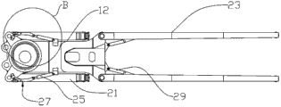
Fig. 5 is the planar structure scheme drawing when drawing in of support leg device shown in Figure 3.
Fig. 6 is the partial enlarged drawing at B position among Fig. 5.
The specific embodiment
To combine accompanying drawing and specific embodiment to come below to further explain of the present invention.
Fig. 2 and Fig. 3 show the support leg device in the some embodiments of the invention, and this support leg device is the automobile-used support leg device of concrete pump, with thinking that concrete pump truck provides support in the course of the work, prevent to overturn.This support leg device can be installed on the chassis 10 of concrete pump truck in certain embodiments, and this chassis 10 is as the concrete pump chassis, pumparound, boom system, hydraulic efficiency pressure system and the electric-control system etc. that also are equipped with usually on it (figure does not show).Be appreciated that ground, in some other embodiment, this support leg device also can be applied to car hosit etc., and other need on the construction machinery and equipment that supporting leg supports.
Support leg device comprises two oscillating type front leg struts 21 and two oscillating type rear support legs 23; This two front leg strut 21 is articulated in two of rotary table 12 front portions respectively and connects on the otic placodes 123; This two rear support leg 23 is articulated in two of rotary table 12 rear portions respectively and connects on the otic placode 125, and this two front leg strut 21 and this two rear support leg 23 all can swing back and forth in the plane at rotary table 12 places.In certain embodiments; Be subject to the restriction in pump truck space, front leg strut 21 is designed to the structure of similar telescopic type antenna, and can also stretch at length direction; And the length of length after it stretches out and rear support leg 23 is suitable; So pump truck is suitable at the bearing force of four direction, and front leg strut 21 shown in Figure 2 has swung to job position, but does not extend along its length as yet.
Be provided with first oil cylinder 25 and connecting rod mechanism 27 between each front leg strut 21 and the rotary table 12; First oil cylinder, 25 1 ends are articulated on the rotary table 12; Connecting rod mechanism 27 links to each other first oil cylinder 25 with front leg strut 21; Be used for the propulsive effort that first oil cylinder 25 produces is passed to front leg strut 21, rotate with respect to rotary table 12 to drive this front leg strut 21.Connecting rod mechanism 27 is provided with the stroke that can shorten first oil cylinder 25, and the manufacturing of first oil cylinder 25 and maintenance cost are reduced, and in addition, can also shorten the time that front leg strut 21 opens or draws in, has improved work efficiency.Be appreciated that ground, in other some embodiment, also can adopt other telescopic actuating device to substitute first oil cylinder 25.
In certain embodiments, because the position at rear support leg 23 places away from swing type mechanism, can supply the space of rear support leg 23 placements more more than needed, rear support leg 23 and 29 designs of second oil cylinder are bigger with the degree of freedom of arranging.As shown in the figure; Be provided with second oil cylinder 29 between each rear support leg 23 and the rotary table 12; Second oil cylinder, 29 1 ends are articulated in the aft end face 121 of rotary table 12, and the other end is articulated in the medial surface 231 of rear support leg 23, rotate with respect to rotary table 12 to promote rear support leg 23.Be appreciated that ground, in certain embodiments, as required, rear support leg 23 also can adopt the driver train the same with front leg strut 21.
Fig. 3 and shown in Figure 4 for another example, connecting rod mechanism 27 comprises first connecting rod 270 and second connecting rod 272.One end of first connecting rod 270 is articulated on the front leg strut 21, and the other end is articulated on first oil cylinder 25.One end of second connecting rod 272 is articulated on the rotary table 12, and the other end is articulated in the middle part of first connecting rod 270.First connecting rod 270, second connecting rod 272, front leg strut 21 and rotary table 12 constitute a lanar four rod mechanism.
In certain embodiments; Second connecting rod 272 and the distance of first connecting rod 270 hinged places to first connecting rod 270 and front leg strut 21 hinged places; Less than second connecting rod 272 and the distance of first connecting rod 270 hinged places to said first connecting rod 270 and first oil cylinder, 25 hinged places; So, can produce leverage, obtain amplification after the propulsive effort that first oil cylinder 25 is produced passes to front leg strut 21 through connecting rod mechanism 27.In addition, first connecting rod 270 and first oil cylinder, 25 pivotally attached ends curve inwardly, and the propulsive effort that the oil cylinder 25 of winning is produced is converted into the propulsive effort to front leg strut 21 more; Make the transmission efficiency of propulsive effort be improved; So, obtained bigger lifting the service life of an aspect total, another aspect can reduce the size of first oil cylinder 25; Further cost-cutting, and can alleviate the weight of pump truck.
As shown in Figure 2 again; The end face of front leg strut 21 becomes to have jut 210, the end face of rotary table 12 to be formed with jut 126,127 near the lateral border place, wherein; Jut 126 is positioned on the connection otic placode 123 of rotary table 12, and is adjacent to front leg strut 21 and rotary table 12 hinged places; Jut 127 is positioned at rotary table 12 end faces middle part near side edge.The end of first connecting rod 270 is articulated on the jut 210; The end of second connecting rod 272 is articulated on the jut 126; The end of first oil cylinder 25 is articulated on the jut 127, and so, first oil cylinder 25 and connecting rod mechanism 27 are positioned at the top of front leg strut 21 and rotary table 12; First oil cylinder 25 and connecting rod mechanism 27 are at the plane motion that is parallel to front leg strut 21 places; Can utilize the space of front leg strut 21 and rotary table 12 vertical direction well, reduce in when making front leg strut 21 gatherings and the gap between the rotary table 12, thereby make pump truck compact more.Be appreciated that ground, as required, first oil cylinder 25 and connecting rod mechanism 27 also can be arranged on the below, bottom surface of front leg strut 21 and rotary table 12, or are arranged on the side of front leg strut 21 and rotary table 12.
More than be merely the preferred embodiments of the present invention, be not limited to the present invention, for a person skilled in the art, the present invention can have various changes and variation.All any modifications of within spirit of the present invention and principle, being done, be equal to replacement, improvement etc., all should be included within protection scope of the present invention.
Claims (12)
1. a construction machinery and equipment is used support leg device; Comprise the oscillating type supporting leg and the telescopic actuating device that are articulated on the engineering machinery chassis; It is characterized in that: also comprise the connecting rod mechanism that is arranged between said oscillating type supporting leg and the said telescopic actuating device; This connecting rod mechanism is used for the propulsive effort that said telescopic actuating device produces is passed to said oscillating type supporting leg, swings with respect to said chassis to drive this oscillating type supporting leg.
2. construction machinery and equipment according to claim 1 is used support leg device, it is characterized in that: said connecting rod mechanism comprises first connecting rod, and an end of this first connecting rod is articulated on the said oscillating type supporting leg, and the other end is articulated on the said telescopic actuating device.
3. construction machinery and equipment according to claim 2 is used support leg device, it is characterized in that: said connecting rod mechanism comprises second connecting rod, and an end of this second connecting rod is articulated on the said chassis, and the other end is articulated on the said first connecting rod.
4. construction machinery and equipment according to claim 3 is used support leg device, it is characterized in that: this second connecting rod and said first connecting rod, oscillating type supporting leg and chassis constitute lanar four rod mechanism.
5. construction machinery and equipment according to claim 3 is used support leg device, it is characterized in that: the said other end of said second connecting rod is articulated in the middle part of said first connecting rod.
6. construction machinery and equipment according to claim 5 is used support leg device; It is characterized in that: said second connecting rod and said first connecting rod hinged place be to the distance of said first connecting rod and said oscillating type supporting leg hinged place, arrives the distance of said first connecting rod and telescopic actuating device hinged place less than said second connecting rod and said first connecting rod hinged place.
7. use support leg device according to any described construction machinery and equipment among the claim 2-6, it is characterized in that: the said other end of said first connecting rod curves inwardly.
8. construction machinery and equipment according to claim 1 is used support leg device, it is characterized in that: said telescopic actuating device is a hydraulic ram.
9. construction machinery and equipment according to claim 1 is used support leg device, it is characterized in that: said telescopic actuating device and said connecting rod mechanism are arranged at above or below the said oscillating type supporting leg.
10. a concrete pump truck comprises the chassis, it is characterized in that: comprise that also each described construction machinery and equipment is used support leg device in the claim 1 to 9, said oscillating type supporting leg and telescopic actuating device are articulated on this chassis.
11. concrete pump truck according to claim 10 is characterized in that: said chassis comprises rotary table, and said oscillating type supporting leg and telescopic actuating device are articulated on this rotary table.
12. concrete pump truck according to claim 11 is characterized in that: said oscillating type supporting leg is articulated in the front portion of this rotary table, and is close to the side of this rotary table when drawing in.
Priority Applications (2)
| Application Number | Priority Date | Filing Date | Title |
|---|---|---|---|
| CN2011103247869A CN102442281B (en) | 2011-10-24 | 2011-10-24 | Support leg device for engineering machinery and concrete pump truck |
| PCT/CN2012/082685 WO2013060232A1 (en) | 2011-10-24 | 2012-10-10 | Leg device for engineering machinery and concrete pump truck |
Applications Claiming Priority (1)
| Application Number | Priority Date | Filing Date | Title |
|---|---|---|---|
| CN2011103247869A CN102442281B (en) | 2011-10-24 | 2011-10-24 | Support leg device for engineering machinery and concrete pump truck |
Publications (2)
| Publication Number | Publication Date |
|---|---|
| CN102442281A true CN102442281A (en) | 2012-05-09 |
| CN102442281B CN102442281B (en) | 2013-12-04 |
Family
ID=46005361
Family Applications (1)
| Application Number | Title | Priority Date | Filing Date |
|---|---|---|---|
| CN2011103247869A Active CN102442281B (en) | 2011-10-24 | 2011-10-24 | Support leg device for engineering machinery and concrete pump truck |
Country Status (2)
| Country | Link |
|---|---|
| CN (1) | CN102442281B (en) |
| WO (1) | WO2013060232A1 (en) |
Cited By (4)
| Publication number | Priority date | Publication date | Assignee | Title |
|---|---|---|---|---|
| CN102991477A (en) * | 2012-12-05 | 2013-03-27 | 中联重科股份有限公司 | Engineering machine and supporting leg device thereof |
| WO2013060232A1 (en) * | 2011-10-24 | 2013-05-02 | 中联重科股份有限公司 | Leg device for engineering machinery and concrete pump truck |
| WO2014166670A1 (en) * | 2013-04-11 | 2014-10-16 | Putzmeister Engineering Gmbh | Mobile concrete pump with distributing boom and support device |
| CN112282370A (en) * | 2020-09-28 | 2021-01-29 | 湖南响箭重工科技有限公司 | Pump truck chassis landing leg structure and pump truck |
Families Citing this family (2)
| Publication number | Priority date | Publication date | Assignee | Title |
|---|---|---|---|---|
| DE102014209565A1 (en) * | 2014-05-20 | 2015-11-26 | Putzmeister Engineering Gmbh | Mobile concrete pump with a support structure |
| CN104002775A (en) * | 2014-06-09 | 2014-08-27 | 安徽星马专用汽车有限公司 | Concrete pump truck and support device thereof |
Citations (4)
| Publication number | Priority date | Publication date | Assignee | Title |
|---|---|---|---|---|
| FR2498140A1 (en) * | 1981-01-16 | 1982-07-23 | Liebherr Hydraulikbagger | SETTING DEVICE FOR EXCAVATORS, CRANES OR THE LIKE |
| CN2592786Y (en) * | 2002-12-31 | 2003-12-17 | 三一重工股份有限公司 | Connecting-rod mechanism for pump vehicle |
| CN2691968Y (en) * | 2004-02-27 | 2005-04-13 | 广东粤海汽车有限公司 | Operation supporting mechanism of span regulutable road vehicle or engineering equipment |
| CN2868787Y (en) * | 2005-12-31 | 2007-02-14 | 三一重工股份有限公司 | Telescopic feet for walking machinery and concrete pump vehicle with same |
Family Cites Families (8)
| Publication number | Priority date | Publication date | Assignee | Title |
|---|---|---|---|---|
| FR2418126A1 (en) * | 1978-02-28 | 1979-09-21 | Poclain Sa | MOBILE DEVICE CONTAINING A STABILIZATION DEVICE |
| US6089603A (en) * | 1998-11-19 | 2000-07-18 | Ackley; Paul C. | Vehicle stabilization system |
| US6257619B1 (en) * | 1999-06-30 | 2001-07-10 | Caterpillar Inc. | Multiple position stabilizer leg |
| GR1003759B (en) * | 2000-09-01 | 2002-01-18 | Τερζης Παναγιωτη Γεωργιος | HYDRAULIC CAR LIFT. |
| JP2002079922A (en) * | 2000-09-08 | 2002-03-19 | Furukawa Co Ltd | Vehicle supporting device |
| CN201842065U (en) * | 2010-10-21 | 2011-05-25 | 山东建设机械股份有限公司 | Swing type rear ground jack of heavy-load self-discharging type mixed mortar bulk silo transport cart |
| CN102120442A (en) * | 2011-02-22 | 2011-07-13 | 湖南运想路面机械有限公司 | Hydraulic support leg |
| CN102442281B (en) * | 2011-10-24 | 2013-12-04 | 中联重科股份有限公司 | Support leg device for engineering machinery and concrete pump truck |
-
2011
- 2011-10-24 CN CN2011103247869A patent/CN102442281B/en active Active
-
2012
- 2012-10-10 WO PCT/CN2012/082685 patent/WO2013060232A1/en active Application Filing
Patent Citations (4)
| Publication number | Priority date | Publication date | Assignee | Title |
|---|---|---|---|---|
| FR2498140A1 (en) * | 1981-01-16 | 1982-07-23 | Liebherr Hydraulikbagger | SETTING DEVICE FOR EXCAVATORS, CRANES OR THE LIKE |
| CN2592786Y (en) * | 2002-12-31 | 2003-12-17 | 三一重工股份有限公司 | Connecting-rod mechanism for pump vehicle |
| CN2691968Y (en) * | 2004-02-27 | 2005-04-13 | 广东粤海汽车有限公司 | Operation supporting mechanism of span regulutable road vehicle or engineering equipment |
| CN2868787Y (en) * | 2005-12-31 | 2007-02-14 | 三一重工股份有限公司 | Telescopic feet for walking machinery and concrete pump vehicle with same |
Cited By (8)
| Publication number | Priority date | Publication date | Assignee | Title |
|---|---|---|---|---|
| WO2013060232A1 (en) * | 2011-10-24 | 2013-05-02 | 中联重科股份有限公司 | Leg device for engineering machinery and concrete pump truck |
| CN102991477A (en) * | 2012-12-05 | 2013-03-27 | 中联重科股份有限公司 | Engineering machine and supporting leg device thereof |
| CN102991477B (en) * | 2012-12-05 | 2015-08-12 | 中联重科股份有限公司 | Construction machinery and equipment and support leg device thereof |
| WO2014166670A1 (en) * | 2013-04-11 | 2014-10-16 | Putzmeister Engineering Gmbh | Mobile concrete pump with distributing boom and support device |
| CN105392945A (en) * | 2013-04-11 | 2016-03-09 | 普茨迈斯特工程有限公司 | Mobile concrete pump with distributing boom and support device |
| US9410334B2 (en) | 2013-04-11 | 2016-08-09 | Putzmeister Engineering Gmbh | Mobile concrete pump with distributing boom and support device |
| CN105392945B (en) * | 2013-04-11 | 2017-09-19 | 普茨迈斯特工程有限公司 | Moveable concrete pump with feed rod and support meanss |
| CN112282370A (en) * | 2020-09-28 | 2021-01-29 | 湖南响箭重工科技有限公司 | Pump truck chassis landing leg structure and pump truck |
Also Published As
| Publication number | Publication date |
|---|---|
| WO2013060232A1 (en) | 2013-05-02 |
| CN102442281B (en) | 2013-12-04 |
Similar Documents
| Publication | Publication Date | Title |
|---|---|---|
| CN102442281B (en) | Support leg device for engineering machinery and concrete pump truck | |
| CN201292227Y (en) | Front swing support of truck crane and truck crane having the same | |
| CN102444149B (en) | Multifunctional emergency rescue vehicle | |
| CN103523664B (en) | Single-girder hanger and reach stacker | |
| CN101397850A (en) | Folding type arm support link mechanism and concrete pump vehicle by using the same | |
| CN104555760A (en) | Telescopic boom structure and engineering vehicle | |
| CN104085799A (en) | Pull type lorry-mounted crane with self-walking function | |
| CN107054502B (en) | Omnidirectional mobile robot chassis with liftable structure | |
| CN103832315A (en) | Road wrecker with sliding platform mechanism | |
| CN105236297A (en) | Pneumatic lifting device | |
| CN105197804A (en) | Stable type gantry crane | |
| CN201670689U (en) | Novel forklift structure | |
| CN101691195A (en) | Rotary telescopic boom forklift | |
| CN207632457U (en) | A kind of scissor aerial work platform | |
| CN202187714U (en) | Novel self-lifting and hoisting device for crawler-type drilling machine | |
| CN203271146U (en) | Movable type cantilever crane equipment and concrete conveying equipment for concrete pump | |
| CN201882815U (en) | Elevator boom and self disassembling and assembling device thereof | |
| CN202988108U (en) | Folding-type grain conveyer belt | |
| CN102991477B (en) | Construction machinery and equipment and support leg device thereof | |
| CN202643180U (en) | Oil cylinder-driving turnover mechanism for support oil cylinder | |
| CN201534767U (en) | Diagonal bracing device capable of lifting object to be braced | |
| CN203845779U (en) | Cantilever crane structure of foldable overhead working truck with embedded oil cylinder | |
| CN102786012A (en) | Large-tonnage lift platform | |
| CN107521618B (en) | A kind of functional module mounting device | |
| CN202279648U (en) | Lorry-mounted crane base |
Legal Events
| Date | Code | Title | Description |
|---|---|---|---|
| C06 | Publication | ||
| PB01 | Publication | ||
| C10 | Entry into substantive examination | ||
| SE01 | Entry into force of request for substantive examination | ||
| C14 | Grant of patent or utility model | ||
| GR01 | Patent grant |