CN102405148A - Axial thrust control for gearing - Google Patents
Axial thrust control for gearing Download PDFInfo
- Publication number
- CN102405148A CN102405148A CN2010800175504A CN201080017550A CN102405148A CN 102405148 A CN102405148 A CN 102405148A CN 2010800175504 A CN2010800175504 A CN 2010800175504A CN 201080017550 A CN201080017550 A CN 201080017550A CN 102405148 A CN102405148 A CN 102405148A
- Authority
- CN
- China
- Prior art keywords
- thrust
- end cap
- wheel motor
- outer end
- planetary gear
- Prior art date
- Legal status (The legal status is an assumption and is not a legal conclusion. Google has not performed a legal analysis and makes no representation as to the accuracy of the status listed.)
- Granted
Links
Images


Classifications
-
- B—PERFORMING OPERATIONS; TRANSPORTING
- B60—VEHICLES IN GENERAL
- B60K—ARRANGEMENT OR MOUNTING OF PROPULSION UNITS OR OF TRANSMISSIONS IN VEHICLES; ARRANGEMENT OR MOUNTING OF PLURAL DIVERSE PRIME-MOVERS IN VEHICLES; AUXILIARY DRIVES FOR VEHICLES; INSTRUMENTATION OR DASHBOARDS FOR VEHICLES; ARRANGEMENTS IN CONNECTION WITH COOLING, AIR INTAKE, GAS EXHAUST OR FUEL SUPPLY OF PROPULSION UNITS IN VEHICLES
- B60K17/00—Arrangement or mounting of transmissions in vehicles
- B60K17/04—Arrangement or mounting of transmissions in vehicles characterised by arrangement, location, or kind of gearing
- B60K17/043—Transmission unit disposed in on near the vehicle wheel, or between the differential gear unit and the wheel
- B60K17/046—Transmission unit disposed in on near the vehicle wheel, or between the differential gear unit and the wheel with planetary gearing having orbital motion
-
- B—PERFORMING OPERATIONS; TRANSPORTING
- B60—VEHICLES IN GENERAL
- B60K—ARRANGEMENT OR MOUNTING OF PROPULSION UNITS OR OF TRANSMISSIONS IN VEHICLES; ARRANGEMENT OR MOUNTING OF PLURAL DIVERSE PRIME-MOVERS IN VEHICLES; AUXILIARY DRIVES FOR VEHICLES; INSTRUMENTATION OR DASHBOARDS FOR VEHICLES; ARRANGEMENTS IN CONNECTION WITH COOLING, AIR INTAKE, GAS EXHAUST OR FUEL SUPPLY OF PROPULSION UNITS IN VEHICLES
- B60K7/00—Disposition of motor in, or adjacent to, traction wheel
- B60K7/0007—Disposition of motor in, or adjacent to, traction wheel the motor being electric
-
- F—MECHANICAL ENGINEERING; LIGHTING; HEATING; WEAPONS; BLASTING
- F16—ENGINEERING ELEMENTS AND UNITS; GENERAL MEASURES FOR PRODUCING AND MAINTAINING EFFECTIVE FUNCTIONING OF MACHINES OR INSTALLATIONS; THERMAL INSULATION IN GENERAL
- F16C—SHAFTS; FLEXIBLE SHAFTS; ELEMENTS OR CRANKSHAFT MECHANISMS; ROTARY BODIES OTHER THAN GEARING ELEMENTS; BEARINGS
- F16C19/00—Bearings with rolling contact, for exclusively rotary movement
- F16C19/54—Systems consisting of a plurality of bearings with rolling friction
-
- F—MECHANICAL ENGINEERING; LIGHTING; HEATING; WEAPONS; BLASTING
- F16—ENGINEERING ELEMENTS AND UNITS; GENERAL MEASURES FOR PRODUCING AND MAINTAINING EFFECTIVE FUNCTIONING OF MACHINES OR INSTALLATIONS; THERMAL INSULATION IN GENERAL
- F16C—SHAFTS; FLEXIBLE SHAFTS; ELEMENTS OR CRANKSHAFT MECHANISMS; ROTARY BODIES OTHER THAN GEARING ELEMENTS; BEARINGS
- F16C35/00—Rigid support of bearing units; Housings, e.g. caps, covers
- F16C35/04—Rigid support of bearing units; Housings, e.g. caps, covers in the case of ball or roller bearings
- F16C35/06—Mounting or dismounting of ball or roller bearings; Fixing them onto shaft or in housing
-
- B—PERFORMING OPERATIONS; TRANSPORTING
- B60—VEHICLES IN GENERAL
- B60K—ARRANGEMENT OR MOUNTING OF PROPULSION UNITS OR OF TRANSMISSIONS IN VEHICLES; ARRANGEMENT OR MOUNTING OF PLURAL DIVERSE PRIME-MOVERS IN VEHICLES; AUXILIARY DRIVES FOR VEHICLES; INSTRUMENTATION OR DASHBOARDS FOR VEHICLES; ARRANGEMENTS IN CONNECTION WITH COOLING, AIR INTAKE, GAS EXHAUST OR FUEL SUPPLY OF PROPULSION UNITS IN VEHICLES
- B60K7/00—Disposition of motor in, or adjacent to, traction wheel
- B60K2007/0038—Disposition of motor in, or adjacent to, traction wheel the motor moving together with the wheel axle
-
- B—PERFORMING OPERATIONS; TRANSPORTING
- B60—VEHICLES IN GENERAL
- B60K—ARRANGEMENT OR MOUNTING OF PROPULSION UNITS OR OF TRANSMISSIONS IN VEHICLES; ARRANGEMENT OR MOUNTING OF PLURAL DIVERSE PRIME-MOVERS IN VEHICLES; AUXILIARY DRIVES FOR VEHICLES; INSTRUMENTATION OR DASHBOARDS FOR VEHICLES; ARRANGEMENTS IN CONNECTION WITH COOLING, AIR INTAKE, GAS EXHAUST OR FUEL SUPPLY OF PROPULSION UNITS IN VEHICLES
- B60K7/00—Disposition of motor in, or adjacent to, traction wheel
- B60K2007/0092—Disposition of motor in, or adjacent to, traction wheel the motor axle being coaxial to the wheel axle
-
- B—PERFORMING OPERATIONS; TRANSPORTING
- B60—VEHICLES IN GENERAL
- B60Y—INDEXING SCHEME RELATING TO ASPECTS CROSS-CUTTING VEHICLE TECHNOLOGY
- B60Y2200/00—Type of vehicle
- B60Y2200/10—Road Vehicles
- B60Y2200/14—Trucks; Load vehicles, Busses
- B60Y2200/142—Heavy duty trucks
-
- F—MECHANICAL ENGINEERING; LIGHTING; HEATING; WEAPONS; BLASTING
- F16—ENGINEERING ELEMENTS AND UNITS; GENERAL MEASURES FOR PRODUCING AND MAINTAINING EFFECTIVE FUNCTIONING OF MACHINES OR INSTALLATIONS; THERMAL INSULATION IN GENERAL
- F16C—SHAFTS; FLEXIBLE SHAFTS; ELEMENTS OR CRANKSHAFT MECHANISMS; ROTARY BODIES OTHER THAN GEARING ELEMENTS; BEARINGS
- F16C2361/00—Apparatus or articles in engineering in general
- F16C2361/61—Toothed gear systems, e.g. support of pinion shafts
-
- F—MECHANICAL ENGINEERING; LIGHTING; HEATING; WEAPONS; BLASTING
- F16—ENGINEERING ELEMENTS AND UNITS; GENERAL MEASURES FOR PRODUCING AND MAINTAINING EFFECTIVE FUNCTIONING OF MACHINES OR INSTALLATIONS; THERMAL INSULATION IN GENERAL
- F16H—GEARING
- F16H1/00—Toothed gearings for conveying rotary motion
- F16H1/28—Toothed gearings for conveying rotary motion with gears having orbital motion
- F16H1/46—Systems consisting of a plurality of gear trains each with orbital gears, i.e. systems having three or more central gears
Landscapes
- Engineering & Computer Science (AREA)
- Mechanical Engineering (AREA)
- General Engineering & Computer Science (AREA)
- Chemical & Material Sciences (AREA)
- Combustion & Propulsion (AREA)
- Transportation (AREA)
- Rolling Contact Bearings (AREA)
- Retarders (AREA)
- General Details Of Gearings (AREA)
- Arrangement Or Mounting Of Propulsion Units For Vehicles (AREA)
- Mounting Of Bearings Or Others (AREA)
Abstract
An outboard thrust bearing assembly can include: a drawbolt, an inner end cap, an outer end cap, and a race of thrust bearings; the drawbolt for clamping the inner end cap to the outer end cap and about a pinion gear of a planetary gear, wherein the race of thrust bearings can be retained in place by the outer end cap, the pinion gear, a planetary gear carrier and a hub cap. A wheel motor and a vehicle are disclosed.
Description
Technical field
The present invention relates to land craft, particularly relate to the restriction of the axial thrust of wheel motor in the heavy wares.
Background technology
Large truck such as the truck that is used for mining activity, uses electric wheel motor to drive usually.Wheel motor is got involved in the rear axle of truck, and each wheel motor drives a dual wheel assembly.In representative type wheel motor device, electro-motor is connected with reducing gearbox; Reducing gearbox and then be secured to the vehicle wheel component that comprises tyre and rim.Wheel motor provides tractive force, and gear case plays torque multiplier/retarder simultaneously.Can imagine that the wheel motor that is used for large truck (such as in mining activity) often stands huge wearing and tearing and pressure.Except rotating wearing and tearing and pressure, the axial thrust that non-expection produces can be brought very big problem.
For example, in some cases, gear case comprises two-stage planet-shaped gear assembly; The input of gear case is provided by the floating pinion/miniature gears of electrical motor driven.Usually each epicyclic gear stage comprises a miniature gears, three planetary wheels and an outer ring gear.
Under serious torque load, the longitudinal travel of engaging gear can appear in planetary gear train.These displacement meetings cause the axial load of single gear and the axial load of whole epicyclic gear stage.Some power such as the power that in normal operation, possibly occur (and lateral impact load), can cause driving device to depart from control position and stand inordinate wear.This can cause too early gearbox fault and unplanned maintenance event.Obviously, these incidents bring a lot of time and money costs can for the operator of heavy wares.
Because above-mentioned reason must be designed with the device that can control axial force and the too early worn-down ill-effect of control in the train of gears.Typically, spin or cylindrical bearing are assembled in and are used to control the axial force on arbitrary direction in the gear case.
In the prior art, bearing distributes in whole gear case, and is arranged under the radially ingear situation of nonintervention wheel word, control thrust.The radial floating of intervening gear can apply load radially and cause premature failure to bearing.Unfortunately, the distribution of bearing assembly in whole gear case causes making complexity increases and error accumulation.Component count will be higher, and gear case will need the dividing wall of a load-bearing.
In addition, the distribution of bearing assembly in gear case also makes the manufacturing of each wheel motor more thorny, because bearing must suitably assemble and with specific order.Between normal defects liability period, the simple scrutiny program of bearing impassabitity detects effectively, because bearing can not clearly be seen.Correspondingly, the assessment of wear-out of a bearing needs a large amount of dismounting and standing time.
Therefore, need improve one's methods with equipment with axial thrust or longitudinal travel in the limiting wheel motor gear case.Preferably, improved method and apparatus provides the maintenance of simplification for user and operator, and supports the relatively not too rapid visual inspection of effort.
Summary of the invention
Among one embodiment: the present invention includes a kind of external thrust bearing assembly, said external thrust bearing assembly comprises: draw bolt (draw bolt), internal end cover, outer end cap and a circle thrust baring; Said draw bolt is used for said internal end cover is fastened to said outer end cap, and internal end cover is fastened to planetary miniature gears; Wherein, this circle thrust baring remains on original position through outer end cap, miniature gears, planetary gear carrier and wheel hub cover.
Among one embodiment: the present invention includes a kind of wheel motor; Said wheel motor comprises: traction electric machine; The input shaft that is used for drive gear casing, said input shaft is used to drive first order planetary gear set, and said first order planetary gear set drives second stage planetary gear set then; And external thrust bearing assembly, be used for the axial thrust in the limiting gear case.
Among one embodiment: the present invention includes a kind of vehicle; Said vehicle comprises at least one wheel motor; Said wheel motor comprises: traction electric machine; The input shaft that is used for drive gear casing, said input shaft is used to drive first order planetary gear set, and said first order planetary gear set drives second stage planetary gear set then; And external thrust bearing assembly, be used for the axial thrust in the limiting gear case.
Description of drawings
In claims, particularly point out theme of the present invention, and clearly required entitlement.Aforementioned and other characteristics of the present invention and advantage will combine the specific embodiment and accompanying drawing to be elaborated.Description of drawings is following:
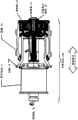
Fig. 1 is the lateral plan that comprises the cross-country car of dual wheel assembly;
Fig. 2 is the section-drawing that prior art is used to drive the wheel motor of cross-country car shown in Figure 1;
Fig. 3 is the section-drawing according to wheel motor of the present invention;
Fig. 4 is the part sectional view of the gear case of wheel motor embodiment;
Fig. 5 and Fig. 6 are the section-drawings of the additional embodiment of gear case; And
Fig. 7 A to Fig. 7 C is referred to as Fig. 7, has described the embodiment of prior art thrust baring.
The specific embodiment
The invention discloses and be used for the axially method and apparatus of displacement (also referring to " axial thrust " or " axial motion ") of limiting wheel motor (such as the wheel motor of cross-country car employing) gear case.Usually, said method and apparatus is supported rapid visual inspection, and the not too simplification M R or the displacement of effort.Therefore, the wheel motor that the present invention provides for the user, it is more economical many to operate than the prior art wheel motor.
Please refer to Fig. 1, the exemplary cross-country car 1 shown in it also can refer to " truck " perhaps " heavy wares " and similar with it other equipment.In this example, cross-country car 1 each side of corresponding rear axle has a wheel motor 10.In this embodiment, each wheel motor 10 provides propulsive force for cross-country car 1.Usually, the vehicle-mounted motor of cross-country car 1 provides electric current for each wheel motor 10.Certainly, the various aspects of the cross-country car 1 that this paper provided are only as exemplary embodiment, and unrestricted the present invention.
Can infer that cross-country car 1 can be any in the multiple vehicle.In addition, in certain embodiments, in some limited range, this vehicle can be used for road driving at least.The example of the heavy wares of wheel motor 10 be can use, mining truck, dump truck, wheel type loader, spading machine, bulldozer, excavating machine, rubbish tip-car, backhoe, carrying implement or the like comprised.
Please refer to Fig. 2, it is the part sectional view of the wheel motor 10 of prior art embodiment.In this example, wheel motor 10 comprises traction electric machine 5 (motive electro-motor normally is provided) and gear case 7.The prime power that gear case 7 conversion traction electric machines 5 provide also provides rotation energy for main shaft 6.Then, main shaft 6 rotation wheel hubs and vehicle wheel component (not shown) are with driving cars 1.
As shown in Figure 2, gear case 7 of the prior art comprises multiple axial-thrust bearing 8, comprises that promptly many circle bearings are with limit axial motion (that is, along moving on any direction of X axle).The axial motion that usually occurs in this vehicle is the component movement of non-expection, non-expectation.
Unfortunately, embodiment shown in Figure 2 is complicated design.More specifically, in whole gear case 7, introduce a plurality of thrust barings 8 and can bring many engineering challenges.For example, these challenges comprise the balance of accurate limit axial thrust, provide simultaneously to have the strong wheel motor 10 of tolerance that is fit to various service conditions.
In addition, this design require usually than the expection more on the spot the maintenance, and require a great deal of time with money to be used for daily service.For example, accomplish a plurality of axial-thrust bearings 20 are checked such simple task, require at least gear case 7 is dismantled.It is contemplated that this just requires car 1 not work for a long time.
Correspondingly, to simplify the prior art design and eliminate or reduce relevant issues needarousal proposition of the present invention.Or rather, through example, the distribution of available technology adopting thrust baring in whole gear case made loading or replacement bearing require great effort unusually.Owing to possibly stand radial weight, prior art design-calculated tight tolerance is unfavorable.In order to address this problem, trend of prior art design-calculated is in gear case, to introduce optional feature and characteristic.Certainly, this has caused more maintenance problem.Thereby improvement design of the present invention can bring lot of advantages.
Shown in Figure 3 for improving the embodiment of wheel motor 100.Improve wheel motor 100 and comprise traction electric machine 11, main shaft 12 and wheel hub 14 and other this parts.Improve wheel motor 100 and also comprise the gear case 15 that has significant improvement with respect to prior art.One of improvement of gear case 15 is that this is improved to the user and brings a lot of advantages with the form of " external thrust bearing assembly ".
In the gear case 15 of improvement wheel motor 100 external thrust baring 30 is installed.External thrust baring 30 can be by the user easily, obtain apace, and can be by maintenance apace.Advantageously, the thrust baring that is used for external thrust bearing assembly all is placed in " external " zone, perhaps is placed in certain zone of the gear case 15 that the user can simply obtain on the spot.
More carefully observe now and improve wheel motor 100.Like Fig. 3 and shown in Figure 4 for improving the exemplary embodiment of wheel motor 100.In this example, traction electric machine 11 comprises the axle that axially is connected to gear case through miniature gears input shaft 23.When input shaft 23 rotated, moment of torsion was passed to first order planetary gear set 21.First order planetary gear set 21 has amplified moment of torsion (also having reduced speed) and this moment of torsion has been delivered to second stage planetary gear set 22.Moment of torsion from second stage planetary gear set 22 is passed to the wheel hub 14 that rotates around main shaft 12.The tyre and rim (not shown) is secured to wheel hub 14.
As shown in Figure 4, the center of second stage planetary gear set 22 is a second stage miniature gears 24.Second stage miniature gears 24 comprises the outer end cap 42 outside placing inboard internal end cover 41 and placing.Draw bolt 51 is placed as the center through second stage miniature gears 24, and internal end cover 41 is fastened to outer end cap 42, and " clamping " power is provided in fact.
Each end cap 41,42 is secured to second stage miniature gears 24 through gripping power.In addition, in certain embodiments, a plurality of bolts 44 can be arranged in around the circumference of outer end cap 42, thereby are fastened to second stage miniature gears 24.Between the second stage of second stage planetary gear set 22 carriage 16 and outer end cap 42 and second stage miniature gears 24, be furnished with the external thrust baring 30 of at least one circle.External thrust baring 30 is secured to three appropriate locations between the parts usually.More specifically, external thrust baring 30 is set at around the circumference at terminal of second stage miniature gears 24, and is installed in the central area of second stage carriage 16, and is fastened on the appropriate location through outer end cap 42.Be provided at the certain translation degree of radial direction (for example, in the Y direction or around the X axle) can for when thinking fit external thrust baring 30.
Notice that in whole disclosure text, observing parts usually is that (initial point of directions X) begins from the left side, and ends at the right side.According to regular situation, left side or left part refer to " inboard ", and the right side that is exposed at work refers to " outside ".Being considered to " axial " along moving of X axle, maybe can be " inwardly " or " outside "; And be considered to " radially " along the motion of Y axle (being orthogonal to the axle of X axle).
Internal end cover 41, outer end cap 42, draw bolt 51 and external thrust baring 30 are referred to as " external thrust bearing assembly ".What certainly can understand is that said external thrust bearing assembly can also comprise some other parts (for example, second stage miniature gears 24).Correspondingly, this usual manner has ubiquity, is not to be limited to the present invention.
In this example, internal end cover 41 comprises the thread center that is used to receive draw bolt 51.Correspondingly, draw bolt 51 can pass the center of outer end cap 42 and insert and be tightened, such as using pipe wrench, so that apply an amount of moment.Internal end cover 41 can adopt casting, machine up or other similar technology manufacturings with outer end cap 42.In certain embodiments, like the discussion part of following Fig. 5 and Fig. 6, internal end cover 41 can comprise additional subassembly with outer end cap 42.
In addition, also comprise wheel hub cover 31.Wheel hub cover 31 is provided with supporting O shape ring usually, to prevent that lubricant in the gear case 15 is to the immersion of external leakage and foreign impurity.And as shown in Figure 4 in certain embodiments, wheel hub cover 31 can limit the axial motion of external thrust baring 30.
Usually, external thrust baring 30 adopts the bearing that can bear extreme loads.The example of thrust baring 30 is as shown in Figure 7, and further discusses in this article.
In certain embodiments, shown in Fig. 4 (and Fig. 6), external thrust bearing assembly comprises two circle thrust barings.Correspondingly, external thrust bearing assembly can absorb or limit inside or outside axial thrust well.Forward Fig. 5 and Fig. 6 now to, provided additional embodiment.
Please refer to Fig. 5, it has provided the additional embodiment of improving wheel motor 100.The key feature of this non-restrictive example is opposite shown in direction and Fig. 3 and Fig. 4 of draw bolt 51.Or rather, the nut head of draw bolt 51 is positioned at internal end cover 41 places, and the end of draw bolt 51 is fastened with nuts and washers 55 simultaneously.In the inboard, draw bolt 51 is surrounded by bearing distance piece 52 usually.The thickness of bearing distance piece 52 is equal to the thickness of the nut head of draw bolt 51 usually.Bearing distance piece 52 is commonly used to minimize the towing of draw bolt 51 on rotation direction, and keeps firm location.In certain embodiments, bearing distance piece is processed by copper or other metal with similar characteristics.Bearing distance piece 52 is that first order input pinion shaft 23 provides certain stop surface when the miniature gears axial float.Should be noted that towards the surface of bearing distance piece 52 and rotate (that is, the gear according to the first order compares) with different speed.Correspondingly, the embodiment of suitable bearing distance piece 52 needs to bear this dynamic force usually.
Bearing distance piece 52 is secured to axial location through interior dowel disc 53 usually with draw bolt 51.Interior dowel disc 53 is secured to second stage miniature gears 56 through the 53 peripheral bolts of dowel disc in passing usually.
Turn to external component now, draw bolt 51 from second stage miniature gears 56 across and into at least one group of external thrust baring 30.External thrust baring 30 or abbreviate " thrust baring " as and carry draw bolt 51, the longitudinal travel in the limiting gear case 15 simultaneously.Usually thrust baring 30 is arranged in the second stage planet carrier 16 with the mode of conventional mounting thrust baring.For example, thrust baring 30 can be assembled in the groove with package size of second stage planet carrier 16 securely.In case in place, thrust baring 30 uses outside fix dish 54 fastening usually.Outside fix dish 54 periphery or the central part office of dowel disc 54 is at least outside arrived second stage planet carrier 16 by bolt.Usually draw bolt 51 passes behind the center of outside fix dish 54 outwards outstandingly, and uses nut and that aural grommet 55 (or use connection of equivalent type fastener) is arranged is fastening.Wheel hub cover 31 is used for guard block and avoids the infringement that external force causes.In addition, O shape ring 57 can be placed under the wheel hub cover 31.
Fig. 6 has described the embodiment according to gear case 15 of the present invention, the embodiment that is similar among Fig. 5 to be provided.Notice that in Fig. 6 thrust baring 30 comprises two groups of bearings.In this embodiment, thrust baring 30 is configured to absorb or limit the axial thrust on the relative direction.
According to what embodiment provided, one group or two groups of thrust barings place the outer side (also can add many circle thrust barings as required) of gear case 15.Thrust baring is embedded in the planet carrier of the second stage, rather than is placed in the train of gears.Thereby, can obtain thrust baring 30 easily through removing wheel hub cover 31.In operation, the thrust that first group of planetary wheel 21 and second group of planetary wheel 22 produced is controlled by external thrust baring 30.Notice that according to the type of for example selected bearing, the load that is stood can be selected a circle or two circles (or more circles) thrust baring with other these type of factors.In operation, the axial thrust towards lateral wheel that is produced is delivered to external thrust baring 30 via second stage miniature gears.The axial thrust that is in the opposite direction produced is pulled bolt 51 and 53,54 of dowel discs bear.Draw bolt 51 is clamped together two groups of planets, and therefore the thrust on arbitrary direction is applied to external thrust baring 30.
Fig. 7 A is referred to as Fig. 7 to Fig. 7 C, has described the many aspects of prior art thrust baring, and these thrust barings can be used in the improved wheel motor 100.Fig. 7 A is depicted as the fluid type thrust baring.In fluid type thrust baring 81, axial thrust is supported on the thin layer of pressure fluid, and therefore realizes low towing.Fig. 7 B is depicted as spin type thrust baring 82.Spin type thrust baring is made up of the ball-bearing casing that is supported in the annulus, is generally used for having in the low-thrust application of less radial weight.Fig. 7 C is depicted as tapered roller bearing 83.Tapered roller bearing generally includes conical roller, and the axle of conical roller is a bit converging on bearing axis all.The diameter of wide end of the length of roller and roller and narrow end is through carefully calculating so that accurate taper to be provided, and makes each end of roller on bearing surface, roll reposefully and non-slip.
Usually, external thrust bearing assembly uses spin thrust baring and/or tapered roller bearing.Yet the thrust baring of other types also may be utilized.
The thrust towards lateral wheel that the input pinion shaft produces is transmitted through bearing distance piece, arrives external thrust baring 30 through second stage planetary wheel then; External then thrust baring 30 limit axial thrusts.Axial thrust on the inward direction is passed to internal end cover 41, and draw bolt 51 is inwardly spurred.Inside pulling is limited by outer end cap 42, and outer end cap 42 is delivered to external thrust baring 30 with inside thrust.In certain embodiments, the compare balancing force of train of gears of input thrust that pinion shaft produced is very little, can ignore usually.Usually the input pinion shaft axially floats on its position, to allow het expansion.Or rather, for example should be noted that input pinion shaft 23 generally includes axial float in a small amount, to avoid because of the caused harmful load of different het expansions to bearing.
Should be noted in the discussion above that based on being arranged at the property obtained that bring gear case 15 outer ends, should select this thrust baring that can dismantle easily and replace from the outside usually.In addition, the determining dimensions of thrust baring and miscellaneous part need consider that with selecting permission dismounting second stage miniature gears 56 together with external thrust bearing assembly, so, need not to start driving device and traction electric machine 11, and the cross-country car 1 that casts anchor just can be towed.Embodiment among this paper just provides the scheme that is suitable for this dismounting.
In certain embodiments, external thrust baring 30 floats (can reduce or avoid the radial weight of thrust baring) diametrically, but still is suitable for receiving the axial thrust along on arbitrary direction of X axle.In certain embodiments, the installation of draw bolt 51 can be reversed, and parts can fine be adjusted on every side; Can find the part difference that caused through comparison diagram 5, Fig. 6 and Fig. 3, Fig. 4.
Through the description of this invention, should be noted that advantages more of the present invention.These advantages comprise: the wearing and tearing of limit thrust bearing, because outboard bearing is because there is lower speed the position at its place; Be easier to make and the simple designs of cost still less.For example, because following factor, make and be simplified and more economically: needing to have avoided the introducing of the gear case dividing wall of bearing thrust, thereby simplified manufacturing process; Reduced the requirement of the accuracy of manufacture in the gear case; Realized the modular of planetary gear set; The parts in the whole gear case have been reduced; Has the simpler installation of group's dress risk of errors.In addition, make and obtain thrust baring from the outside and become feasible, thereby can more effectively detect the bearing situation, and make thrust baring not influenced by radial weight.
Certainly, the explanation of this paper only is to improving the introduction of wheel motor 100.Also can comprise other embodiment.For example, improve the thrust baring (such as fluid type thrust baring 81) that wheel motor 100 can comprise one or more groups replacement or be increased to bearing distance piece 52
The invention discloses low-maintenance wheel motor 100.Will be appreciated that the tire of any number can be mounted and and improvement wheel motor 100 supporting uses.Low-maintenance wheel motor 100 can be used in polytype vehicle.In addition, the various aspects of improvement wheel motor 100 disclosed herein can be used for the driving of other types.For example, the parts in the gear case 15 as herein described can be used for any driving type that needs limit axial thrust (such as differential, hydraulic pressure and other).
In one embodiment: vehicle comprises at least one wheel motor; Said wheel motor comprises: traction electric machine; The input shaft that is used for drive gear casing, said input shaft is used to drive first order planetary gear set, and said first order planetary gear set drives second stage planetary gear set then; And external thrust bearing assembly, be used for the axial thrust in the limiting gear case.
In one embodiment: external thrust bearing assembly comprises: internal end cover, outer end cap and a circle thrust baring; Draw bolt is used for said internal end cover is fastened to said outer end cap, and internal end cover is fastened to planetary miniature gears.This circle thrust baring can remain on original position through outer end cap, miniature gears, planetary gear carrier and wheel hub cover.
In one embodiment: wheel motor comprises: traction electric machine, be used for the input shaft of drive gear casing, and said input shaft is used to drive first order planetary gear set, and said first order planetary gear set drives second stage planetary gear set then; And external thrust bearing assembly, be used for the axial thrust in the limiting gear case.
In the embodiment that changes: (i) miniature gears and planetary gear carrier can comprise second stage planetary wheel; (ii) at least one in internal end cover and the outer end cap comprise straight-through portion with bolted connection to miniature gears; (iii) internal end cover can comprise at least one in bearing distance piece and the dowel disc; (iv) internal end cover can comprise the thread center that is used to receive draw bolt; (v) outer end cap can comprise dowel disc; (vi) outer end cap may further include and is used for the nuts and washers that the terminal of draw bolt is fastening; (vii) thrust baring can comprise the spin profile shaft hold with the roller-type bearing at least a; (viii) assembly may further include the O shape ring that is used to seal wheel hub cover; (ix) external thrust bearing assembly can comprise: internal end cover, outer end cap and a circle thrust baring; Draw bolt is used for said internal end cover is fastened to said outer end cap, and internal end cover is fastened to planetary miniature gears; Wherein, this circle thrust baring can remain on original position through outer end cap, miniature gears, planetary gear carrier and wheel hub cover; (x) thrust baring be suitable for obtaining on the spot, at least a in the cross-check sum dismounting; (xi) gear case is suitable for dismantling miniature gears and draw bolt, internal end cover, outer end cap and thrust baring on the spot; (xii) thrust baring of external thrust bearing assembly is suitable in the radial direction float; And/or (xiii) vehicle can comprise a kind of in mining truck, dump truck, wheel type loader, spading machine, bulldozer, excavating machine, rubbish tip-car, backhoe and the carrying implement.
Although reference example property embodiment has described the present invention, one skilled in the art will appreciate that without departing from the present invention, can make different the change, and substitute with equivalents.In addition, under the situation that does not break away from essential scope of the present invention, can make many remodeling so that specific situation or material are fit to the content of the present invention's explanation.Therefore, the present invention is intended to be not limited to the specific embodiment of the disclosed optimal mode of the present invention, and is intended to comprise all embodiment that drop in the accessory claim scope.
Claims (18)
1. external thrust bearing assembly comprises:
Internal end cover, outer end cap and a circle thrust baring; And
Draw bolt is used for said internal end cover is fastened to said outer end cap, and internal end cover is fastened to planetary miniature gears;
Wherein, this circle thrust baring remains on original position through outer end cap, miniature gears, planetary gear carrier and wheel hub cover.
2. assembly as claimed in claim 1 is characterized in that said miniature gears and planetary gear carrier are included in the planetary wheel of the second stage.
3. like each described assembly among the claim 1-2, it is characterized in that, at least one in said internal end cover and the outer end cap comprise straight-through portion with bolted connection to miniature gears.
4. like each described assembly among the claim 1-3, it is characterized in that said internal end cover comprises at least one in bearing distance piece and the dowel disc.
5. like each described assembly among the claim 1-4, it is characterized in that said internal end cover comprises the thread center that is used to receive draw bolt.
6. like each described assembly among the claim 1-5, it is characterized in that said outer end cap comprises dowel disc.
7. like each described assembly among the claim 1-6, it is characterized in that said outer end cap further comprises and is used for the nuts and washers that the terminal of draw bolt is fastening.
8. like each described assembly among the claim 1-7, it is characterized in that, this circle thrust baring comprise the spin profile shaft hold with the roller-type bearing at least a.
9. like each described assembly among the claim 1-8, further comprise the O shape ring that is used to seal wheel hub cover.
10. a wheel motor comprises each described external thrust bearing assembly among the claim 1-9.
11. a wheel motor comprises:
Traction electric machine is used for the input shaft of drive gear casing, and said input shaft is used to drive first order planetary gear set, and said first order planetary gear set drives second stage planetary gear set then; And external thrust bearing assembly, be used for the axial thrust in the limiting gear case.
12. wheel motor as claimed in claim 11 is characterized in that, said external thrust bearing assembly comprises:
Internal end cover, outer end cap and a circle thrust baring; And
Draw bolt is used for said internal end cover is fastened to said outer end cap, and internal end cover is fastened to planetary miniature gears; Wherein, this circle thrust baring can remain on original position through outer end cap, miniature gears, planetary gear carrier and wheel hub cover.
13., it is characterized in that the thrust baring of said external thrust bearing assembly is suitable for obtaining, at least a in the cross-check sum dismounting like each described wheel motor among the claim 11-12 on the spot.
14., it is characterized in that said gear case is suitable for dismantling external thrust bearing assembly on the spot like each described wheel motor among the claim 11-13.
15., it is characterized in that the thrust baring of said external thrust bearing assembly is suitable in the radial direction float like each described wheel motor among the claim 11-14.
16. a vehicle comprises each described wheel motor among the claim 11-15.
17. vehicle; Comprise wheel motor, said wheel motor comprises: traction electric machine is used for the input shaft of drive gear casing; Said input shaft is used to drive first order planetary gear set, and said first order planetary gear set drives second stage planetary gear set then; And external thrust bearing assembly, be used for the axial thrust in the limiting gear case.
18., comprise a kind of in mining truck, dump truck, wheel type loader, spading machine, bulldozer, excavating machine, rubbish tip-car, backhoe and the carrying implement like each described vehicle among the claim 16-17.
Applications Claiming Priority (3)
| Application Number | Priority Date | Filing Date | Title |
|---|---|---|---|
| US12/409,063 US8038570B2 (en) | 2009-03-23 | 2009-03-23 | Axial thrust control for gearing |
| US12/409,063 | 2009-03-23 | ||
| PCT/US2010/028288 WO2010111253A2 (en) | 2009-03-23 | 2010-03-23 | Axial thrust control for gearing |
Publications (2)
| Publication Number | Publication Date |
|---|---|
| CN102405148A true CN102405148A (en) | 2012-04-04 |
| CN102405148B CN102405148B (en) | 2015-09-09 |
Family
ID=42736520
Family Applications (1)
| Application Number | Title | Priority Date | Filing Date |
|---|---|---|---|
| CN201080017550.4A Active CN102405148B (en) | 2009-03-23 | 2010-03-23 | Axial thrust for driving device controls |
Country Status (6)
| Country | Link |
|---|---|
| US (2) | US8038570B2 (en) |
| CN (1) | CN102405148B (en) |
| AU (1) | AU2010229478A1 (en) |
| BR (1) | BRPI1014187A2 (en) |
| RU (1) | RU2011142781A (en) |
| WO (1) | WO2010111253A2 (en) |
Families Citing this family (9)
| Publication number | Priority date | Publication date | Assignee | Title |
|---|---|---|---|---|
| DE102011003765A1 (en) * | 2011-02-08 | 2012-08-09 | Schaeffler Technologies Gmbh & Co. Kg | Assembly of a planetary gear |
| DE112012000712T5 (en) * | 2011-02-08 | 2013-11-14 | General Electric Company | Cylindrical roller bearing device |
| JP5685111B2 (en) | 2011-03-07 | 2015-03-18 | Ntn株式会社 | Electric vehicle drive |
| US9074677B2 (en) * | 2011-03-14 | 2015-07-07 | Arvinmeritor Technology, Llc | Carrier assembly with threaded adjustment member |
| JP5799731B2 (en) * | 2011-10-12 | 2015-10-28 | 日産自動車株式会社 | Axle support structure |
| US9308811B2 (en) * | 2012-05-10 | 2016-04-12 | Goldhofer Aktiengesellschaft | Drive device for motor vehicles |
| US8727933B2 (en) * | 2012-08-13 | 2014-05-20 | Caterpillar Inc. | Bolt on carrier for integrated final drive with closed circuit hydrostatic motor |
| CN106092566A (en) * | 2016-06-30 | 2016-11-09 | 武汉理工大学 | A kind of by gear-box state of wear visual monitoring system and monitoring method thereof |
| CN110380556A (en) * | 2019-08-19 | 2019-10-25 | 抚顺煤矿电机制造有限责任公司 | A kind of double drive end bearing bracket structures of vertical installation motor |
Citations (6)
| Publication number | Priority date | Publication date | Assignee | Title |
|---|---|---|---|---|
| US3937293A (en) * | 1973-10-26 | 1976-02-10 | Siemens Aktiengesellschaft | Drive arrangement for a track-bound electric self-propelled vehicle |
| US4330045A (en) * | 1979-09-14 | 1982-05-18 | Reliance Electric Company | Vehicle wheel mechanism |
| CN2051318U (en) * | 1989-05-15 | 1990-01-17 | 武汉工业大学 | Rolling-bearing two-speed planetary speed-reducing machine |
| US20050250616A1 (en) * | 2004-05-05 | 2005-11-10 | Beltowski Mark F | Removable thrust washer retainer for a motorized wheel off-highway dump truck |
| JP2008037355A (en) * | 2006-08-09 | 2008-02-21 | Nissan Motor Co Ltd | Electro-motive drive device |
| CN201126005Y (en) * | 2007-12-17 | 2008-10-01 | 南京高速齿轮制造有限公司 | Low wind direction type wind power generator step-up gear box |
Family Cites Families (20)
| Publication number | Priority date | Publication date | Assignee | Title |
|---|---|---|---|---|
| US3770074A (en) * | 1972-04-24 | 1973-11-06 | Gen Motors Corp | Reduction drive for electric axle |
| US3969950A (en) * | 1974-03-04 | 1976-07-20 | Trw Inc. | Drive assembly |
| US4389586A (en) * | 1982-02-22 | 1983-06-21 | General Electric Company | Electric wheel with removable motor |
| US5087229A (en) * | 1991-05-06 | 1992-02-11 | General Motors Corporation | Independently suspended steerable motor wheel apparatus |
| DE4228746C2 (en) * | 1992-08-28 | 2000-11-02 | Linde Ag | Wheel hub drive |
| US5472059A (en) * | 1994-02-15 | 1995-12-05 | Dana Corporation | Wheel end assembly |
| US6588538B2 (en) * | 2001-07-12 | 2003-07-08 | Caterpillar Inc. | Wheel and final drive assembly for a ground driven work machine |
| GB2389827B (en) * | 2002-06-18 | 2005-12-14 | Magnetic Systems Technology Lt | Hub drive system |
| SE525626C2 (en) * | 2003-03-05 | 2005-03-22 | Volvo Constr Equip Holding Se | Device for driving a wheel of a vehicle |
| SE525092C2 (en) * | 2003-04-30 | 2004-11-30 | Volvo Constr Equip Holding Se | Annular means intended to form part of a laying unit, drive device and vehicle |
| US6890282B2 (en) * | 2003-06-11 | 2005-05-10 | Zf Friedrichshafen Ag | Driveline for mobile vehicles |
| JP4353735B2 (en) * | 2003-06-20 | 2009-10-28 | 株式会社ハーモニック・ドライブ・システムズ | Planetary gear set |
| JP4743819B2 (en) * | 2004-01-06 | 2011-08-10 | 株式会社 神崎高級工機製作所 | Reduction gear device |
| JP2007022386A (en) * | 2005-07-19 | 2007-02-01 | Ntn Corp | Electric wheel driving device |
| JP3960553B1 (en) * | 2006-03-31 | 2007-08-15 | 本田技研工業株式会社 | Wheel rotation device for in-wheel motor vehicle |
| JP4501911B2 (en) * | 2006-08-11 | 2010-07-14 | トヨタ自動車株式会社 | In-wheel motor structure |
| US7445067B2 (en) * | 2006-08-31 | 2008-11-04 | American Axle & Manufacturing, Inc. | Electric wheel motor assembly |
| JP4225342B2 (en) * | 2006-10-04 | 2009-02-18 | トヨタ自動車株式会社 | In-wheel motor structure |
| EP2148788B1 (en) * | 2007-04-19 | 2012-05-16 | BluWav Systems, LLC | Wheel motor |
| US8251861B2 (en) * | 2009-07-10 | 2012-08-28 | Arvinmeritor Technology, Llc | Planetary wheel end with piloted sun gear shaft |
-
2009
- 2009-03-23 US US12/409,063 patent/US8038570B2/en not_active Expired - Fee Related
-
2010
- 2010-03-23 RU RU2011142781/11A patent/RU2011142781A/en unknown
- 2010-03-23 CN CN201080017550.4A patent/CN102405148B/en active Active
- 2010-03-23 WO PCT/US2010/028288 patent/WO2010111253A2/en active Application Filing
- 2010-03-23 AU AU2010229478A patent/AU2010229478A1/en not_active Abandoned
- 2010-03-23 BR BRPI1014187A patent/BRPI1014187A2/en not_active IP Right Cessation
-
2011
- 2011-08-18 US US13/212,924 patent/US8365853B2/en active Active
Patent Citations (6)
| Publication number | Priority date | Publication date | Assignee | Title |
|---|---|---|---|---|
| US3937293A (en) * | 1973-10-26 | 1976-02-10 | Siemens Aktiengesellschaft | Drive arrangement for a track-bound electric self-propelled vehicle |
| US4330045A (en) * | 1979-09-14 | 1982-05-18 | Reliance Electric Company | Vehicle wheel mechanism |
| CN2051318U (en) * | 1989-05-15 | 1990-01-17 | 武汉工业大学 | Rolling-bearing two-speed planetary speed-reducing machine |
| US20050250616A1 (en) * | 2004-05-05 | 2005-11-10 | Beltowski Mark F | Removable thrust washer retainer for a motorized wheel off-highway dump truck |
| JP2008037355A (en) * | 2006-08-09 | 2008-02-21 | Nissan Motor Co Ltd | Electro-motive drive device |
| CN201126005Y (en) * | 2007-12-17 | 2008-10-01 | 南京高速齿轮制造有限公司 | Low wind direction type wind power generator step-up gear box |
Also Published As
| Publication number | Publication date |
|---|---|
| BRPI1014187A2 (en) | 2016-04-26 |
| AU2010229478A1 (en) | 2011-10-27 |
| CN102405148B (en) | 2015-09-09 |
| US8038570B2 (en) | 2011-10-18 |
| WO2010111253A2 (en) | 2010-09-30 |
| WO2010111253A3 (en) | 2011-02-17 |
| US20110306462A1 (en) | 2011-12-15 |
| US20100236848A1 (en) | 2010-09-23 |
| US8365853B2 (en) | 2013-02-05 |
| RU2011142781A (en) | 2013-04-27 |
Similar Documents
| Publication | Publication Date | Title |
|---|---|---|
| CN102405148B (en) | Axial thrust for driving device controls | |
| US4330045A (en) | Vehicle wheel mechanism | |
| CA2641532C (en) | Asymmetrical triple-row anti-friction bearing | |
| US5813938A (en) | Wheel mounting hub system | |
| US10513146B2 (en) | Axle assembly having a countershaft | |
| CA2641534C (en) | Multi-row symmetrical rolling bearing | |
| CA2641539C (en) | Asymmetric quadruple-row anti-friction bearing | |
| CN102574464B (en) | For the thrust plate of the bearing of engages drive assembly | |
| JP4490317B2 (en) | Dump truck travel drive device | |
| US5588931A (en) | Planetary reducer and wheel bearing unit | |
| US20160167431A1 (en) | Final Drive Assembly | |
| US6890039B2 (en) | Independently rotating wheels | |
| JP2007162914A (en) | Epicycle reduction gear | |
| US6872163B2 (en) | Planetary wheelend | |
| WO1995013198A1 (en) | Wheel bearing arrangements | |
| JP4610399B2 (en) | Traveling device | |
| US6419325B1 (en) | Wheel bearing arrangement for a dual wheel assembly | |
| CN201221572Y (en) | Triplex row rolling body shaft connecting bearing for automobile engine water pump | |
| US5401218A (en) | Outboard planetary gear assembly for tracked vehicles | |
| CN108473052B (en) | Hub unit | |
| CN201746230U (en) | Non-mandrel crane driven vehicle wheel set | |
| CN210661313U (en) | Wheel-side speed reducer of drive axle of loader | |
| EP2855165B1 (en) | Tapered stud used for connecting the ring gear flange to the axle housing in motor vehicles | |
| CN210454573U (en) | Power shaft transmission structure of chain wheel and flange type hydraulic motor combination | |
| CN112797069A (en) | Conical hub unit |
Legal Events
| Date | Code | Title | Description |
|---|---|---|---|
| C06 | Publication | ||
| PB01 | Publication | ||
| C10 | Entry into substantive examination | ||
| SE01 | Entry into force of request for substantive examination | ||
| ASS | Succession or assignment of patent right |
Owner name: CATERPILLAR GLOBAL MINING EQUIPMENT, LLC Free format text: FORMER OWNER: BUCYRUS MINING EQUIPMENT, INC. Effective date: 20121112 |
|
| C41 | Transfer of patent application or patent right or utility model | ||
| TA01 | Transfer of patent application right |
Effective date of registration: 20121112 Address after: Wisconsin Applicant after: Bucyrus Mining Equipment Inc. Address before: Wisconsin Applicant before: Bucyrus Mining Equipment Inc. |
|
| C14 | Grant of patent or utility model | ||
| GR01 | Patent grant |