CN102387684A - Electronic apparatus - Google Patents
Electronic apparatus Download PDFInfo
- Publication number
- CN102387684A CN102387684A CN2011102594015A CN201110259401A CN102387684A CN 102387684 A CN102387684 A CN 102387684A CN 2011102594015 A CN2011102594015 A CN 2011102594015A CN 201110259401 A CN201110259401 A CN 201110259401A CN 102387684 A CN102387684 A CN 102387684A
- Authority
- CN
- China
- Prior art keywords
- housing
- hinge
- rotating shaft
- notch portion
- face
- Prior art date
- Legal status (The legal status is an assumption and is not a legal conclusion. Google has not performed a legal analysis and makes no representation as to the accuracy of the status listed.)
- Pending
Links
Images


Classifications
-
- H—ELECTRICITY
- H05—ELECTRIC TECHNIQUES NOT OTHERWISE PROVIDED FOR
- H05K—PRINTED CIRCUITS; CASINGS OR CONSTRUCTIONAL DETAILS OF ELECTRIC APPARATUS; MANUFACTURE OF ASSEMBLAGES OF ELECTRICAL COMPONENTS
- H05K5/00—Casings, cabinets or drawers for electric apparatus
- H05K5/02—Details
- H05K5/0217—Mechanical details of casings
- H05K5/0226—Hinges
-
- G—PHYSICS
- G06—COMPUTING; CALCULATING OR COUNTING
- G06F—ELECTRIC DIGITAL DATA PROCESSING
- G06F1/00—Details not covered by groups G06F3/00 - G06F13/00 and G06F21/00
- G06F1/16—Constructional details or arrangements
- G06F1/1613—Constructional details or arrangements for portable computers
- G06F1/1633—Constructional details or arrangements of portable computers not specific to the type of enclosures covered by groups G06F1/1615 - G06F1/1626
- G06F1/1675—Miscellaneous details related to the relative movement between the different enclosures or enclosure parts
- G06F1/1681—Details related solely to hinges
-
- H—ELECTRICITY
- H05—ELECTRIC TECHNIQUES NOT OTHERWISE PROVIDED FOR
- H05K—PRINTED CIRCUITS; CASINGS OR CONSTRUCTIONAL DETAILS OF ELECTRIC APPARATUS; MANUFACTURE OF ASSEMBLAGES OF ELECTRICAL COMPONENTS
- H05K5/00—Casings, cabinets or drawers for electric apparatus
- H05K5/0017—Casings, cabinets or drawers for electric apparatus with operator interface units
Landscapes
- Engineering & Computer Science (AREA)
- Computer Hardware Design (AREA)
- Theoretical Computer Science (AREA)
- Microelectronics & Electronic Packaging (AREA)
- Human Computer Interaction (AREA)
- Physics & Mathematics (AREA)
- General Engineering & Computer Science (AREA)
- General Physics & Mathematics (AREA)
- Telephone Set Structure (AREA)
- Casings For Electric Apparatus (AREA)
- Pivots And Pivotal Connections (AREA)
Abstract
An electronic apparatus includes: a first casing; a second casing; a hinge section which includes a first turning shaft provided at one end portion of the first casing and a second turning shaft provided at one end portion of the second casing and connects the first and second casings so as to be able to be opened or closed in a range from a folded state to a back-to-back state through the first and second turning shafts; a display section provided on one face of the second casing; and a displacement section which displaces the display section to the other end side of the second casing in the folded state and the back-to-back state of the first and second casings and displaces the display section to one end side of the second casing in a spread state of the first and second casings.
Description
Technical field
Present disclosure relates to a kind of electronic equipment, and for example is applicable to through connecting first housing and second housing so that the Foldable electronic device that can open and close forms.
Background technology
In the Foldable electronic device of prior art, first member that is provided with operation keys interconnects through hinge means with second member that is provided with display.First shaft and second shaft are arranged in the hinge means each other side by side; First member (pivotally) rotationally is installed on first shaft so that can rotate, and second member also is installed in rotation on second shaft so that can rotate.
In addition, in hinge means, first rotation section and second rotation section of relative to each other rotating are arranged on first shaft and the second shaft place respectively.In addition, in hinge means, first rotation section and second rotation section interconnect through the interlocking binding.
Therefore, in hinge means, the rotation of first rotation section links through interlocking passes to second rotation section, and rotate with combining with one another first rotation section and second rotation section thus.Like this, electronic equipment is made into and makes win member and second member relative to each other turn over 360 degree (for example, with reference to the open 2008-75747 of japanese unexamined patent (the 8th to 10 page and Fig. 7 to Figure 13)) through hinge means.
Summary of the invention
In having the Foldable electronic device of this configuration, if open first member and second member and for example then operation keys is operated, then carry out various processing according to this operation, the information of the executing state handled of expression is presented on the display thus.
Therefore, in Foldable electronic device, under the situation of opening first member and second member and then operation keys being operated, suitably confirm executing state according to the processing of operation through display.
Incidentally, usually, in Foldable electronic device; When opening first member and second member and then operation keys being operated, operation keys and display the closer to, then the eye movement quantitative change between operation keys and the display must be more little; Thereby alleviated kopiopia, can improve availability thus.
Yet in the Foldable electronic device of prior art, because hinge means is between first member and second member, therefore, operation keys and display are correspondingly away from each other.For this reason, in Foldable electronic device, can not be in order to open first member and second member and when then operation keys to be operated alleviate kopiopia and make the eye movement quantitative change between operation keys and the display little, and have the problem that is difficult to improve availability.
Expectation proposes a kind of electronic equipment that can improve availability.
Embodiment according to present disclosure; A kind of electronic equipment is provided; In this electronic equipment; First housing and second housing interconnect through hinge; This hinge comprises first rotating shaft at first housing, the one end place that is arranged on first housing and second rotating shaft at the place, second housing, one end that is arranged on second housing, so that can pass through first rotating shaft and second rotating shaft open and close in the scope from folded state to state back-to-back, and passes through displaced portions; Be arranged on second housing one side of second housing display part the folded state of first housing and second housing be shifted to the second housing other end side under the state back-to-back, and under the deployed condition of first housing and second housing to the one distolateral displacement of second housing.
Therefore; Embodiment according to present disclosure; Under the deployed condition of first housing and second housing under the situation of visually observing display surface or operation keys and second housing display surface in simultaneously in first housing one side; Reduce the eye movement amount between the interior display surface of display surface or operation keys and second housing one side in first housing one side, thereby can alleviate kopiopia.
Embodiment according to present disclosure; In electronic equipment; Through following configuration; Under the deployed condition of first housing and second housing under the situation of visually observing display surface or operation keys and second housing display surface in simultaneously in first housing one side; Reduced the eye movement amount between the interior display surface of display surface or operation keys and second housing one side in first housing one side; Thereby can alleviate kopiopia, can realize the electronic equipment that availability can be improved thus: first housing and second housing interconnect through hinge, and this hinge comprises first rotating shaft at the place, first housing, one end that is arranged on first housing and is arranged on second rotating shaft at the place, second housing, one end of second housing; So that can be through first rotating shaft and second rotating shaft open and close in scope from folded state to state back-to-back; And through displaced portions, be arranged on second housing one side of second housing display part the folded state of first housing and second housing be shifted to the second housing other end side under the state back-to-back, and under the deployed condition of first housing and second housing to the one distolateral displacement of second housing.
Description of drawings
Fig. 1 is the general perspective that illustrates according to an embodiment of the outward appearance configuration of the Foldable electronic device of present disclosure.
Fig. 2 is the general view of configuration that the notch portion that is used for hinge of first housing is shown.
Fig. 3 is the summary sectional view that the axle formation configuration partly of first housing is shown.
Fig. 4 illustrates the notch portion that is used for hinge of second housing and the general view of the configuration of the notch portion that is used to be shifted.
Fig. 5 is the summary sectional view that the axle formation configuration partly of second housing is shown.
Fig. 6 is the general perspective that the outward appearance configuration of first hinge is shown.
Fig. 7 is the summary sectional view of internal configurations (1) that first hinge is shown.
Fig. 8 is the summary sectional view of internal configurations (2) that first hinge is shown.
Fig. 9 is used to explain first housing and the general perspective that be connected of second housing through first hinge.
Figure 10 is the general perspective that the outward appearance configuration of second hinge is shown.
Figure 11 is the summary sectional view of internal configurations (1) that second hinge is shown.
Figure 12 is the summary sectional view of internal configurations (2) that second hinge is shown.
Figure 13 is used to explain first housing and the general perspective that be connected of second housing through second hinge.
Figure 14 A and Figure 14 B are the skeleton diagrams that is used to explain the variation (1) of the position of first hinge and second hinge when open and close first housing and second housing.
Figure 15 A and Figure 15 B are the skeleton diagrams that is used to explain the variation (2) of the position of first hinge and second hinge when open and close first housing and second housing.
Figure 16 A and Figure 16 B are the skeleton diagrams that is used to explain the variation (3) of the position of first hinge and second hinge when open and close first housing and second housing.
Figure 17 A and Figure 17 B are the skeleton diagrams that is used to explain the variation (4) of the position of first hinge and second hinge when open and close first housing and second housing.
Figure 18 A and Figure 18 B are the skeleton diagrams that is used to explain the variation (5) of the position of first hinge and second hinge when open and close first housing and second housing.
Figure 19 A and Figure 19 B are the general perspectives that is used to explain the open and close (1) of first housing and second housing.
Figure 20 A and Figure 20 B are the general perspectives that is used to explain the open and close (2) of first housing and second housing.
Figure 21 A and Figure 21 B are the general perspectives that is used to explain the open and close (3) of first housing and second housing.
Figure 22 A and Figure 22 B are the general perspectives that is used to explain the open and close (4) of first housing and second housing.
Figure 23 A and Figure 23 B are the general perspectives that is used to explain the open and close (5) of first housing and second housing.
Figure 24 A and Figure 24 B are used to explain the general perspective of second display part according to the displacement (1) of the open and close of first housing and second housing.
Figure 25 A and Figure 25 B are used to explain the general perspective of second display part according to the displacement (2) of the open and close of first housing and second housing.
Figure 26 A and Figure 26 B are used to explain the general perspective of second display part according to the displacement (3) of the open and close of first housing and second housing.
Figure 27 A and Figure 27 B are used to explain the general perspective of second display part according to the displacement (4) of the open and close of first housing and second housing.
Figure 28 A and Figure 28 B are used to explain the general perspective of second display part according to the displacement (5) of the open and close of first housing and second housing.
Figure 29 A and Figure 29 B are used to explain the general perspective of second display part according to the displacement (6) of the open and close of first housing and second housing.
Figure 30 A and Figure 30 B are used to explain the general perspective of second display part according to the displacement (7) of the open and close of first housing and second housing.
Figure 31 A and Figure 31 B are the general perspectives that illustrates according to the shape of the bottom surface of the left cut notch portion of first cam face of another embodiment and second cam face and maintaining part and right cut notch portion.
Embodiment
The embodiment of present disclosure relates to a kind of electronic equipment, comprising: first housing; Second housing; Hinge; Second rotating shaft that it comprises first rotating shaft at the place, an end that is arranged on first housing and is arranged on the place, an end of second housing; And be connected first housing and second housing with second rotating shaft through first rotating shaft, so that can in scope, open or closed from folded state to state back-to-back; Display part, it is arranged on the one side of second housing; And displaced portions, it is at the folded state of first housing and second housing and under the state display part is shifted to the other end side of second housing back-to-back, and under the deployed condition of first housing and second housing, makes the distolateral displacement of display part to second housing.
Hereinafter, with using accompanying drawing to describe the optimal mode (hereinafter, this is also referred to as embodiment) that is used to realize present disclosure.In addition, will describe by following order.
1. embodiment
2. modified example
1. embodiment
1-1. the outward appearance of Foldable electronic device configuration
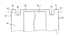
In Fig. 1, Reference numeral 1 overall expression is according to the Foldable electronic device of present disclosure.In such electronic equipment 1, an end of an end of first housing 2 of approximate flattened rectangular and second housing 3 of approximate flattened rectangular interconnects through first hinge 4 and second hinge 5 that each all has the twin shaft configuration.
Therefore, electronic equipment 1 is formed and win housing 2 and second housing 3 can be spent in the scope of 360 degree at 0 of state back-to-back that the folded state that matees each other from one side 2A and one side 3A matees to another side 2B and another side 3B each other open or closure.
Incidentally, in following explanation, also the end with first housing 2 is called first housing, one end, and the other end in the side relative with first housing, one end in first housing 2 is called the first housing other end.
In addition, in following explanation, also with in first housing 2 from first housing, one end towards the direction of the first housing other end and with above-mentioned in the opposite direction, be referred to as the first housing depth direction from the first housing other end towards the direction of first housing, one end.
In addition, in following explanation, also the one side 2A with first housing 2 is called first housing one side 2A, and the another side 2B of first housing 2 is called the first housing another side 2B.
In addition; In following explanation, also with in first housing 2 from first housing one side 2A towards the direction of the first housing another side 2B and with above-mentioned in the opposite direction, be referred to as the first thickness of shell direction from the first housing another side 2B towards the direction of first housing one side 2A.
In addition, in following explanation, also the side 2C with a side of first housing 2 is called the first housing left surface 2C, and the side 2D of the opposite side of first housing 2 is called the first housing right flank 2D.
In addition; In following explanation, also with in first housing 2 from the first housing left surface 2C towards the direction of the first housing right flank 2D and with above-mentioned in the opposite direction, be referred to as the first housing Width from the first housing right flank 2D towards the direction of the first housing left surface 2C.
In addition, in following explanation, also the end with second housing 3 is called second housing, one end, and the other end in the side relative with second housing, one end in second housing 3 is called the second housing other end.
In addition, in following explanation, also with in second housing 3 from second housing, one end towards the direction of the second housing other end and with above-mentioned in the opposite direction, be referred to as the second housing depth direction from the second housing other end towards the direction of second housing, one end.
In addition, in following explanation, also the one side 3A with second housing 3 is called second housing one side 3A, and the another side 3B of second housing 3 is called the second housing another side 3B.
In addition; In following explanation, also with in second housing 3 from second housing one side 3A towards the direction of the second housing another side 3B and with above-mentioned in the opposite direction, be referred to as the second thickness of shell direction from the second housing another side 3B towards the direction of second housing one side 3A.
In addition, in following explanation, also the side 3C with a side of second housing 3 is called the second housing left surface 3C, and the side 3D of the opposite side of second housing 3 is called the second housing right flank 3D.
In addition; In following explanation, also with in second housing 3 from the second housing left surface 3C towards the direction of the second housing right flank 3D and with above-mentioned in the opposite direction, be referred to as the second housing Width from the second housing right flank 3D towards the direction of the second housing left surface 3C.
In this case, first housing 2 and second housing 3 are selected as shape, size and thickness and are equal to each other.Incidentally, in following explanation, also the thickness with first housing 2 and second housing 3 all is called thickness of shell.
In addition; Central portion office at first housing of first housing 2 one side 2A; Under the first display surface 6A exposed state; First display part 6 of approximate flattened rectangular is arranged near first housing, one end (for example, towards the position of the first housing other end away from several millimeters at first housing, one end) on the zone of another distolateral given position of first housing.
Incidentally, in following explanation, in the first display surface 6A of first display part 6, first housing, one a distolateral end also is called as first display surface, one end, and another distolateral other end of first housing also is called as the first display surface other end.
Promptly; In first housing 2; Distance from first housing, one end to first display surface, one end in the middle body of first housing one side 2A is selected as above-mentioned several millimeters, so that first display part 6 is with the state arrangement of first display surface, one end near first housing, one end.
In addition, first transparent touch panel 7 is arranged on the first display surface 6A of first display part 6, to cover the first display surface 6A.Incidentally, first display part 6 that is arranged on first housing one side 2A of first housing 2 is LCD, organic EL (electroluminescence) display etc.
On the other hand; In second housing one side 3A of second housing 3; Approximate rectangular notch portion (hereinafter, this is also referred to as the notch portion that the is used to be shifted) 3E that is used for the display part displacement is formed on from second housing, one end on the zone of another distolateral given position of second housing.
In addition, the notch portion 3E that is used for being shifted in second housing one side 3A of second housing 3, the maintaining part 8 that forms approximate rectangular frame shape is configured to and can on the second housing depth direction, slides.
In addition, maintaining part 8 keeps second display part 9 of approximate flattened rectangular, surrounding the side of this second display part 9 in whole periphery, thereby in second housing one side 3A, exposes the second display surface 9A of second display part 9.
Incidentally, in following explanation, in the second display surface 9A of second display part 9, second housing, one a distolateral end also is called as second display surface, one end, and another distolateral other end of second housing also is called as the second display surface other end.
Then; In maintaining part 8; Four the frame part 8A of side that surround second display part 9 in whole periphery are in the middle of 8D; The degree of depth at the frame part 8A of second housing one distolateral (that is, contacting second display surface, one end) is selected as several millimeters, and it equals the distance from first housing, one end to first display surface, one end.Incidentally, in following explanation, in the middle of 8D, also be called as a distolateral frame part 8A at second housing, one distolateral frame part 8A at four frame part 8A of maintaining part 8.
Therefore; For example; Open with the angle of 180 degree so that first housing one side 2A and second housing one side 3A are when coming into line when first housing 2 and second housing 3, it is distolateral that maintaining part 8 slides into second housing one, thereby can make second display surface, one end near first display surface, one end.
That is, for example, when first housing 2 and second housing 3 were opened with the angle of 180 degree, maintaining part 8 made the second display surface 9A near the first display surface 6A, thereby makes these display surfaces be arranged to as a display surface.
In addition, on the second display surface 9A of second display part 9, be provided with second transparent touch panel 10 to cover the second display surface 9A.Incidentally, second display part 9 that is arranged on the one side 3A of second housing 3 also is LCD, OLED display etc.
Then, the inside of at least one in first housing 2 and second housing 3 accommodate the various circuit parts (not shown) such as control part, storage part etc., and control part is electrically connected to other circuit parts.
In addition, control part also suitably is electrically connected to first display part 6, second display part 9, first touch panel 7 and second touch panel 10.Therefore, for example, control part can show dissimilar images respectively on the second display surface 9A of the first display surface 6A of first display part 6 and second display part 9.
In addition, for example, control part can also be divided into two with single image, and on the second display surface 9A of the first display surface 6A of first display part 6 and second display part 9, shows two images being cut apart.
Promptly; For example; Reach about 180 when spending when first housing 2 and second housing 3 are opened, control part can show single image through using the first display surface 6A and the second display surface 9A as a display surface on the first display surface 6A and the second display surface 9A.
In addition; If under the state of display image on the second display surface 9A of the first display surface 6A of first display part 6 and second display part 9, touch operation is carried out on the surface of first touch panel 7 and second touch panel 10, then control part is carried out according to touch operation and is handled.
In fact, control part can show the image (hereinafter, this also is called as keyboard image) with the various operation keyss that are configured to icon on the first display surface 6A of first display part 6.
Then; If be presented at keyboard image under the state on the first display surface 6A of first display part 6; Touch operation is carried out on surface to first touch panel 7, thus the indication icon, and then control part is carried out the processing of allocating in advance to the icon of being indicated by touch operation.
That is, control part makes the first display surface 6A work as hardware keyboards together with first touch panel 7, thereby according to the image of operation switching displayed on the second display surface 9A to keyboard (keyboard image), and the content of update image.
1-2. the detailed configuration of Foldable electronic device
Next, with the configuration of describing Foldable electronic device 1 in detail.As shown in Figures 2 and 3; In first housing, one end of first housing 2; The notch portion 2E that is used for hinge as follows is formed near the given position of the first housing left surface 2C: the width of this notch portion approximates the width of first hinge 4, and it approximates thickness of shell from first housing, one end to another distolateral degree of depth of first housing.
Incidentally, in following explanation, the notch portion 2E that is used for hinge that also will in first housing, one end, be formed near the given position the first housing left surface 2C is called the first housing left cut notch portion 2E.
In addition; In first housing, one end of first housing 2; Near the first housing right flank 2D given position also is formed with the notch portion 2F that is used for hinge as follows: the width of this notch portion approximates the width of second hinge 5, and it approximates thickness of shell from first housing, one end to another distolateral degree of depth of first housing.
Incidentally, in following explanation, the notch portion 2F that is used for hinge that also will in first housing, one end, be formed near the given position the first housing right flank 2D is called the first housing right cut notch portion 2F.
Then; Part in first housing, one end between the first housing left cut notch portion 2E and the first housing right cut notch portion 2F is formed the even shape of end face (that is the end face of first housing, one end) 2G with right angle contact first housing one side 2A and the first housing another side 2B.
Incidentally; In following explanation; Also the part between the first housing left cut notch portion 2E and the first housing right cut notch portion 2F in first housing, one end is called first housing, one end middle body, and the end face 2G of first housing, one end middle body is called first housing, one end face 2G.
In addition; In first housing, one end, more become axle formation part as describing after a while near the part 2H of the first housing left surface 2C side than the first housing left cut notch portion 2E; Form in the part at this axle, be formed with the rotating shaft when rotating first housing 2 with respect to second housing 3.
Incidentally, in following explanation, also will in first housing, one end, more be called first left-hand axis formation part 2H near the part 2H (that is, axle forms part) of the first housing left surface 2C side than the first housing left cut notch portion 2E.
Form among the part 2H in first left-hand axis; Its first housing, one distolateral end face form along be that center, radius are the circular arc of the corresponding side of the semicircle of cylinder of distance of thickness of shell 1/2 with dummy line VL1, wherein this dummy line VL1 is parallel with the first housing Width and be 1/2 of thickness of shell apart from the distance at the center of end face.
In addition; In first housing, one end, more also become axle formation part as describing after a while near the part 2J of the first housing right flank 2D side than the first housing right cut notch portion 2F; Form in the part rotating shaft when being formed with respect to second housing, 3 rotations, first housing 2 at this axle.
Incidentally, in following explanation, also will in first housing, one end, more be called first right-hand axis formation part 2J near the part 2J (that is, axle forms part) of the first housing right flank 2D side than the first housing right cut notch portion 2F.
In addition; Be similar to first left-hand axis and form part 2H; Form among the part 2J in first right-hand axis, its first housing, one distolateral end face form along be that center, radius are the circular arc of the corresponding side of the semicircle of cylinder of distance of thickness of shell 1/2 with above-mentioned dummy line VL1.
On the other hand, like Fig. 4 and shown in Figure 5, in second housing one side 3A of second housing 3, be formed with aforesaid, the wide notch portion 3E that is used to be shifted of the ratio second display surface 9A.
Yet another is distolateral at second housing, is formed with the notch portion 3E that is used to be shifted, so that reserve the base plate 3K of second housing 3.In addition, distolateral at second housing one, be formed with the notch portion 3E that is used to be shifted, so that the base plate 3K of second housing 3 is so that another distolateral approximate U-shaped is removed from second housing, one end to second housing.
In second housing, one end of second housing 3; Near the second housing left surface 3C given position is formed with towards first housing left cut notch portion notch portion 3F 2E, that be used for hinge; Wherein, This notch portion 3F has the width of the width that approximates first hinge 4, and it approximates thickness of shell from second housing, one end to another distolateral degree of depth of second housing.
Incidentally, in following explanation, also the notch portion 3F that is used for hinge that is formed near the given position the second housing left surface 3C in second housing, one end is called the second housing left cut notch portion 3F.
In this case, the second housing left cut notch portion 3F is formed in the actual part that is cut off in second housing, one end and the part place relevant with the left side of the notch portion 3E that is used to be shifted towards the first above-mentioned housing left cut notch portion 2E.
In addition; In second housing, one end of second housing 3; Near the second housing right flank 3D given position also is formed with towards above-mentioned first housing right cut notch portion notch portion 3G 2F, that be used for hinge, and wherein this notch portion 3G approximates thickness of shell from second housing, one end to another distolateral degree of depth of second housing.
Incidentally, in following explanation, the notch portion 3G that is used for hinge that also will in second housing, one end, be formed near the given position the second housing right flank 3D is called the second housing right cut notch portion 3G.
In this case, the second housing right cut notch portion 3G is formed in the actual part that is cut off in second housing, one end and the part place relevant with the right side of the notch portion 3E that is used to be shifted towards the first above-mentioned housing right cut notch portion 2F.
Then; In second housing, one end, more become axle formation part as describing after a while near the part 3H of the second housing left surface 3C side than the second housing left cut notch portion 3F; Form in the part at this axle, be formed with the rotating shaft when rotating second housing 3 with respect to first housing 2.
Incidentally, in following explanation, also will in second housing, one end, more be called second left-hand axis formation part 3H near the part 3H (that is, axle forms part) of the second housing left surface 3C side than the second housing left cut notch portion 3F.
Form among the part 3H in second left-hand axis; Its second housing, one distolateral end face form along be that center, radius are the circular arc of the corresponding side of the semicircle of cylinder of distance of thickness of shell 1/2 with dummy line VL2, wherein this dummy line VL2 is parallel with the second housing Width and be 1/2 of thickness of shell apart from the distance at the center of end face.
In addition; In second housing, one end, more also become axle formation part as describing after a while near the part 3J of the second housing right flank 3D side than the second housing right cut notch portion 3G; Form in the part at this axle, be formed with the rotating shaft when rotating second housing 3 with respect to first housing 2.
Incidentally, in following explanation, also will in second housing, one end, more be called second right-hand axis formation part 3J near the part 3J (that is, axle forms part) of the second housing right flank 3D side than the second housing right cut notch portion 3G.
In addition; Be similar to second left-hand axis and form part 3H; Form among the part 3J in second right-hand axis, its second housing, one distolateral end face form along be that center, radius are the circular arc of the corresponding side of the semicircle of cylinder of distance of thickness of shell 1/2 with above-mentioned dummy line VL2.
In addition, in maintaining part 8, at one end be formed with 1/2 notch portion (hereinafter, this also the is called the left cut notch portion) 8AX that the degree of depth equals thickness of shell among the body side frame part 8A in the left part of said first shell left cut notch portion 2E.
In addition, in maintaining part 8, at one end also be formed with 1/2 notch portion (hereinafter, this also the is called the right cut notch portion) 8AY that the degree of depth equals thickness of shell among the body side frame part 8A in the right part of said first shell right cut notch portion 2F.
In addition, in maintaining part 8, the end face of a distolateral frame part 8A (that is the end face that first housing one is distolateral, and hereinafter, also be called maintaining part one end face) 8AZ forms with the upper surface of right angle contact one distolateral frame part 8A and the even shape of lower surface.
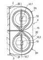
As shown in Figure 6, first hinge 4 has first hinge casing 15, and wherein, the thickness from one side 15A to another side 15B equals thickness of shell, and the distance from the side 15C of a side to the side 15D of opposite side is the width of above-mentioned first hinge 4.
Incidentally, in following explanation, also the one side 15A in first hinge casing 15 is called first hinge one side 15A, and the another side 15B in first hinge casing 15 is called the first hinge another side 15B.
In addition, in following explanation, also the thickness from first hinge one side 15A to the first hinge another side 15B in first hinge casing 15 of first hinge 4 is called the first hinge thickness.
Then; In following explanation, also with in first hinge 4 from first hinge one side 15A towards the direction of the first hinge another side 15B and with above-mentioned in the opposite direction, be referred to as the first hinge thickness direction from the first hinge another side 15B towards the direction of first hinge one side 15A.
In addition, in following explanation, also will be called the first hinge left surface 15C, and will be called the first hinge right flank 15D at the side 15D of the opposite side in first hinge casing 15 at the side 15C of the side in first hinge casing 15.
Then; In following explanation, also with in first hinge 4 from the first hinge left surface 15C towards the direction of the first hinge right flank 15D and with above-mentioned in the opposite direction, be referred to as the first hinge Width from the first hinge right flank 15D towards the direction of the first hinge left surface 15C.
In first hinge casing 15; The end face 15E of one end form along be that center, radius are the circular arc of the corresponding side of the semicircle of cylinder of distance of thickness of shell 1/2 with dummy line VL3, wherein this dummy line VL3 is parallel with the first hinge Width and be 1/2 of thickness of shell apart from the distance at the center of end face 15E.
In addition; In first hinge casing 15; The end face 15F of the other end form along be that center, radius are the circular arc of the corresponding side of the semicircle of cylinder of distance of thickness of shell 1/2 with dummy line VL4, wherein this dummy line VL4 is parallel with the first hinge Width and be 1/2 of thickness of shell apart from the distance at the center of end face 15F.
Incidentally, in following explanation, also the end with first hinge casing 15 is called first hinge, one end, and the other end of first hinge casing 15 is called the first hinge other end.
Then, in following explanation, also with to be referred to as first hinge vertical from the top of the end face 15E of first hinge, one end towards the direction at the top of the end face 15F of the first hinge other end and with this direction in the opposite direction in first hinge 4.
Then, in first hinge casing 15, the length from the top of the circular arc end face 15E of first hinge, one end to the top of the circular arc end face 15F of the first hinge other end is selected as the length that approximates the thickness of shell twice.
Incidentally, in following explanation, also the length from the top of the circular arc end face 15E of first hinge, one end to the top of the circular arc end face 15F of the first hinge other end in first hinge casing 15 is called first hinge length.
In addition, in first hinge casing 15,1/2 the notch portion that equals thickness of shell from the first hinge other end to first hinge, the one distolateral degree of depth is formed on the first hinge right flank 15D side first hinge the other end.
In this case; The part of the first hinge right flank 15D side in first hinge casing 15 becomes cam portion (hereinafter; This also is called first cam portion) 15G, this cam portion is used for making maintaining part 8 displacements according to the open and close of first housing 2 and second housing 3.
That is in first hinge casing 15, be the first cam portion 15G to 1.5 times part bottom surface (hereinafter, this also the is called first cam face) 15GX of notch portion, that length is about thickness of shell, from the top of the circular arc end face 15E of first hinge, one end.Then, the width of the first cam portion 15G (width of the first cam face 15GX) is selected as the width of the left cut notch portion 8AX that equals maintaining part 8.
In addition, in first hinge casing 15, more be selected as than the first cam portion 15G and approximate the actual width that is cut off as the part of the second housing left cut notch portion 3F in second housing, one end of second housing 3 near the width of the part in left side.
In addition, in the first hinge left surface 15C of first hinge casing 15, be a distolateral bore portion 15CX of center and circle with given radius first hinge, one distolateral penetrating with dummy line VL3.
In addition, in the first hinge left surface 15C of first hinge casing 15, be the other end side opening part 15CY of center and the radius circle identical with a distolateral bore portion 15CX another distolateral penetrating of first hinge with dummy line VL4.
Then, to shown in Figure 9, first hinge 4 has columniform first rotating shaft 16 and second rotating shaft, 17 these two rotating shafts like Fig. 7, and the radius of each rotating shaft all approximates the radius of a distolateral bore portion 15CX.In addition, first hinge 4 also has discoidal first pulley 18 and second pulley, 19 these two pulleys that are contained in first hinge casing 15.
Incidentally, Fig. 7 illustrates that first housing 2 and second housing 3 are opened with the angle of 180 degree so that the state (hereinafter, this also is called deployed condition) that first housing one side 2A and second housing one side 3A come into line.In addition, Fig. 8 and Fig. 9 illustrate the state that first housing 2 and second housing 3 are opened with the angle of about 120 degree.
In first hinge casing 15, first rotating shaft 16 is inserted among the distolateral bore portion 15CX of first hinge casing 15, so that can rotate around dummy line VL3.
Then, under the dummy line VL3 and the corresponding state of dummy line VL1 of the center of rotation that becomes first rotating shaft 16, be projected into the inwall that first hinge casing, 15 outside ends are fixed in first left-hand axis formation part 2H of first housing 2 in first rotating shaft 16.
In addition, under the corresponding state of central axis of the dummy line VL3 and first pulley 18, the other end that in first rotating shaft 16, enters into first hinge casing 15 is fixed in the middle body of the one side of first pulley 18.
In addition, in first hinge casing 15, second rotating shaft 17 and first rotating shaft 16 are inserted among the other end side opening part 15CY of first hinge casing 15 abreast, so that can rotate around dummy line VL4.
Under the dummy line VL4 and the corresponding state of dummy line VL2 of the center of rotation that becomes second rotating shaft 17, be projected into the inwall that first hinge casing, 15 outside ends are fixed in second left-hand axis formation part 3H of second housing 3 in second rotating shaft 17.
In addition, under the corresponding state of central axis of the dummy line VL4 and second pulley 19, the other end that enters into first hinge casing 15 in second rotating shaft 17 is fixed in the middle body of the one side of second pulley 19.
Like this, in first hinge 4, when open and close first housing 2 and second housing 3, combine with open and close, first pulley 18 in first hinge casing 15, rotates with first rotating shaft 16 and second pulley 19 also rotates with second rotating shaft 17.
In addition, in first hinge 4, line 20 twines with splayed to the side of second pulley 19 from the side of first pulley 18.Then, the part of line 20 is directed and is fixed in the another side of first pulley 18, and another part is directed and is fixed in the another side of second pulley 19.
Incidentally; When assembling electronic equipment 1; For example; Open first left-hand axis thus with the angle of 180 degree at first housing 2 and second housing 3 and form under the state that the end face of part 2H and end face that second left-hand axis forms part 3H be in contact with one another, line 20 is twined also is fixed in first pulley 18 and second pulley 19.
Like this; In first hinge 4; When open and close first housing 2 and second housing 3, first pulley 18 and second pulley 19 relative to each other rotate synchronously with one another in opposite direction, and line 20 is slided on the side of first pulley 18 and second pulley 19.
That is, in first hinge 4, when open and close first housing 2 and second housing 3, prevent that only second rotating shaft 17 and second pulley 19 from rotating with respect to first rotating shaft 16 and first pulley 18.
In addition, in first hinge 4, when open and close first housing 2 and second housing 3, prevent that also only first rotating shaft 16 and first pulley 18 from rotating with respect to second rotating shaft 17 and second pulley 19.
Like this, the left side of the left side of first housing, one end of first hinge, 4 connections, first housing 2 and second housing, one end of second housing 3, thus make win housing 2 and second housing, 3 open and closes.
On the other hand, shown in figure 10, first hinge casing 15 that second hinge 5 has the shape and first hinge 4 is second hinge casing 25 of plane symmetry.That is, in second hinge casing 25, the thickness from one side 25A to another side 25B is selected as and equals thickness of shell, and the distance from the side 25C of a side to the side 25D of opposite side is the width of above-mentioned second hinge 5.
Incidentally, in following explanation, also the one side 25A in second hinge casing 25 is called second hinge one side 25A, and the another side 25B in second hinge casing 25 is called the second hinge another side 25B.
In addition, in following explanation, also the thickness from second hinge one side 25A to the second hinge another side 25B in second hinge casing 25 of second hinge 5 is called the second hinge thickness.
Then; In following explanation, also with in second hinge 5 from second hinge one side 25A towards the direction of the second hinge another side 25B and with above-mentioned in the opposite direction, be referred to as the second hinge thickness direction from the second hinge another side 25B towards the direction of second hinge one side 25A.
In addition, in following explanation, also the side 25C with the side in second hinge casing 25 is called the second hinge left surface 25C, and the side 25D of the opposite side in second hinge casing 25 is called the second hinge right flank 25D.
Then; In following explanation, also with in second hinge 5 from the second hinge left surface 25C towards the direction of the second hinge right flank 25D and with above-mentioned in the opposite direction, be referred to as the second hinge Width from the second hinge right flank 25D towards the direction of the second hinge left surface 25C.
In second hinge casing 25; The end face 25E of one end form along be that center, radius are the circular arc of the corresponding side of the semicircle of cylinder of distance of thickness of shell 1/2 with dummy line VL5, wherein this dummy line VL5 is parallel with the second hinge Width and be 1/2 of thickness of shell apart from the distance at the center of end face 25E.
In addition; In second hinge casing 25; The end face 25F of the other end forms along being that center, radius are the circular arc of the corresponding side of the semicircle of cylinder of distance of thickness of shell 1/2 with dummy line VL6, and wherein this dummy line VL6 is parallel with the second hinge Width and be 1/2 of thickness of shell apart from the distance at the center of end face 25F.
Incidentally, in following explanation, also the end with second hinge casing 25 is called second hinge, one end, and the other end of second hinge casing 25 is called the second hinge other end.
Then, in following explanation, also with to be referred to as second hinge vertical from the top of the end face 25E of second hinge, one end towards the direction at the top of the end face 25F of the second hinge other end and with this direction in the opposite direction in second hinge 5.
Then, in second hinge casing 25, be selected as the length of the twice that approximates thickness of shell to the length at the top of the circular arc end face 25F of the second hinge other end from the top of the circular arc end face 25E of second hinge, one end.
Incidentally, in following explanation, also the length from the top of the circular arc end face 25E of second hinge, one end to the top of the circular arc end face 25F of the second hinge other end in second hinge casing 25 is called second hinge length.
In addition, in second hinge casing 25,1/2 the notch portion that equals thickness of shell from the second hinge other end to second hinge, the one distolateral degree of depth is formed on the second hinge left surface 25C side in second hinge the other end.
In this case; The part of the second hinge left surface 25C side in second hinge casing 25 becomes cam portion (hereinafter; This also is called second cam portion) 25G, this cam portion is used for making maintaining part 8 displacements according to the open and close of first housing 2 and second housing 3.
That is, in second hinge casing 25, become the second cam portion 25G from the top of the circular arc end face 25E of second hinge, one end to 1.5 times part bottom surface (hereinafter, this also the is called second cam face) 25GX of notch portion, that length is about thickness of shell.Then, the width of the second cam portion 25G (width of the second cam face 25GX) is selected as the width of the right cut notch portion 8AY that equals maintaining part 8.
In addition, in second hinge casing 25, more be selected as than the second cam portion 25G and approximate the actual width that is cut off as the part of the second housing right cut notch portion 3G in second housing, one end of second housing 3 near the width of the part on right side.
In addition, in the second hinge right flank 25D of second hinge casing 25, be a distolateral bore portion 25DX of center and the radius circle identical with above-mentioned one distolateral bore portion 15CX second hinge, one distolateral penetrating with dummy line VL5.
In addition, in the second hinge right flank 25D of second hinge casing 25, be the other end side opening part 25DY of center and the radius circle identical with an above-mentioned distolateral bore portion 15CX another distolateral penetrating of second hinge with dummy line VL6.
Then, to shown in Figure 13, second hinge 5 has columniform first rotating shaft 26 and second rotating shaft, 27 these two rotating shafts like Figure 11, and the radius of each rotating shaft all approximates the radius of above-mentioned one distolateral bore portion 15CX.In addition, second hinge 5 also has discoidal first pulley 28 and second pulley, 29 these two pulleys that are contained in second hinge casing 25.
Incidentally, Figure 11 illustrates the deployed condition of first housing 2 and second housing 3, and Figure 12 and Figure 13 illustrate the state that first housing 2 and second housing 3 are opened with the angle of about 120 degree.
In second hinge casing 25, first rotating shaft 26 is inserted among the distolateral bore portion 25DX of second hinge casing 25, so that can rotate around dummy line VL5.
Then, under the dummy line VL5 and the corresponding state of dummy line VL1 of the center of rotation that becomes first rotating shaft 26, be projected into the inwall that second hinge casing, 25 outside ends are fixed in first right-hand axis formation part 2J of first housing 2 in first rotating shaft 26.
In addition, under the dummy line VL5 state corresponding with the central axis of first pulley 28, the other end that enters into second hinge casing 25 in first rotating shaft 26 is fixed in the middle body of the one side of first pulley 28.
In addition, in second hinge casing 25, second rotating shaft 27 and first rotating shaft 26 are inserted among the other end side opening part 25DY of second hinge casing 25 abreast, so that can rotate around dummy line VL6.
Under the dummy line VL6 and the corresponding state of dummy line VL2 of the center of rotation that becomes second rotating shaft 27, be projected into the inwall that second hinge casing, 25 outside ends are fixed in second right-hand axis formation part 3J of second housing 3 in second rotating shaft 27.
In addition, under the corresponding state of central axis of the dummy line VL6 and second pulley 29, the other end that enters into second hinge casing 25 in second rotating shaft 27 is fixed in the middle body of the one side of second pulley 29.
Like this; In second hinge 5, when open and close first housing 2 and second housing 3, combine with open and close; First pulley 28 rotates with first rotating shaft 26 in second hinge casing 25, and second pulley 29 also rotates with second rotating shaft 27.
In addition, in second hinge 5, line 30 twines with splayed to the side of second pulley 29 from the side of first pulley 28.In addition, the part of line 30 is directed and is fixed in the another side of first pulley 28, and another part is directed and is fixed in the another side of second pulley 29.
Incidentally; When assembling electronic equipment 1; For example; Open first right-hand axis thus with the angle of 180 degree at first housing 2 and second housing 3 and form under the state that the end face of part 2J and end face that second right-hand axis forms part 3J be in contact with one another, line 30 is twined also is fixed in first pulley 28 and second pulley 29.
Like this; In second hinge 5; When open and close first housing 2 and second housing 3, first pulley 28 and second pulley 29 relative to each other rotate synchronously with one another in opposite direction, and line 30 is slided on the side of first pulley 28 and second pulley 29.
That is, in second hinge 5, be similar to the situation of the first above-mentioned hinge 4, when open and close first housing 2 and second housing 3, prevent that only second rotating shaft 27 and second pulley 29 from rotating with respect to first rotating shaft 26 and first pulley 28.
In addition, in second hinge 5, when open and close first housing 2 and second housing 3, prevent that also only first rotating shaft 26 and first pulley 28 from rotating with respect to second rotating shaft 27 and second pulley 29.
Like this, the right side of the right side of first housing, one end of second hinge, 5 connections, first housing 2 and second housing, one end of second housing 3, thus make win housing 2 and second housing, 3 open and closes.
In fact, shown in Figure 14 A to Figure 18 B, in first housing 2, each end face in the end face that the end face of first left-hand axis formation part 2H and first right-hand axis form part 2J all forms circular arc to describe semicircle, as stated.
In addition, in second housing 3, each end face in the end face that the end face of second left-hand axis formation part 3H and second right-hand axis form part 3J all forms circular arc to describe semicircle, as stated.
Then; In first hinge 4; As stated, in assembling during electronic equipment 1, line 20 forms state that the end face of part 2H and end face that second left-hand axis forms part 3H contact with each other down by winding and be fixed in first pulley 18 and second pulley 19 in first left-hand axis.
In addition; In second hinge 5; As stated, in assembling during electronic equipment 1, line 30 forms state that the end face of part 2J and end face that second right-hand axis forms part 3J contact with each other down by winding and be fixed in first pulley 28 and second pulley 29 in first right-hand axis.
In addition, in first housing 2, plane symmetry ground forms the left side and the right side of first housing, one end, and same, and in second housing 3, plane symmetry ground forms the left side and the right side of second housing, one end.In addition, also plane symmetry ground forms first hinge 4 and second hinge 5.
Correspondingly; If operate first housing 2 and second housing 3 with when using electronic equipment 1 from external opening or closure; Then form that part 2H and second left-hand axis form that part 3H contacts with each other and first right-hand axis forms part 2J and second right-hand axis and forms under the state that part 3J also contacts with each other in first left-hand axis, first hinge 4 and second hinge 5 change the position synchronously with one another.
Like this, first hinge 4 and second hinge 5 are freely being opened or closed win housing 2 and second housing 3 in the scope of the angle of angle to 360 degree of 0 degree.
That is, when using electronic equipment 1, first hinge 4 and second hinge 5 make the housing 2 and second housing 3 is freely opened or closure of winning, and first housing, one end can not hung on (catch) second housing one end at all.
In addition, in first hinge 4, the line 20 that is wrapped on first pulley 18 and second pulley 19 is intersecting under the state away from these pulleys between first pulley 18 and second pulley 19.
Then, open or the situation of closed first housing 2 and second housing 3 under, first hinge 4 makes the cross section displacement of line 20 between first pulley 18 and second pulley 19, and does not make line 20 with respect to first pulley 18 and 19 slips of second pulley.
In addition, in second hinge 5, the line 30 that is wrapped on first pulley 28 and second pulley 29 is intersecting under the state away from these pulleys between first pulley 28 and second pulley 29 equally.
Then, open or the situation of closed first housing 2 and second housing 3 under, second hinge 5 makes the cross section displacement of line 30 between first pulley 28 and second pulley 29, and does not make line 30 with respect to first pulley 28 and 29 slips of second pulley.
Like this; Opening or when closed first housing 2 and second housing 3, first hinge 4 and second hinge 5 can make first housing 2 and second housing 3 around first rotating shaft 16 and 26 and second rotating shaft 17 and 27, rotation relatively in opposite direction synchronously with one another.
That is, the coupling part that first hinge 4 and second hinge 5 prevent first housing 2 and second housing 3 ladder occurs owing to any rotation only, thereby win housing 2 and second housing 3 are opened or closed as interconnecting through an axle.
Then, in first hinge 4, first rotating shaft 16 and second rotating shaft 17 are rotated in distolateral bore portion 15CX of first hinge casing 15 and other end side opening part 15CY respectively.
In addition, in first hinge 4, as stated, first hinge length is selected as the length of the twice that approximates thickness of shell, and the first hinge thickness also is selected as and approximates thickness of shell.
Correspondingly; Opening or when closed first housing 2 and second housing 3; In the first housing left cut notch portion 2E and the second housing left cut notch portion 3F, first hinge 4 changes the position under vertically parallel with the dummy line VL7 that is orthogonal to two dummy line VL1 and the VL2 state of first hinge.
In addition, equally in second hinge 5, first rotating shaft 26 and second rotating shaft 27 are rotated in distolateral bore portion 25DX of second hinge casing 25 and other end side opening part 25DY respectively.
In addition, in second hinge 5, as stated, second hinge length is selected as the length of the twice that approximates thickness of shell equally, and the second hinge thickness also is selected as and approximates thickness of shell.
Correspondingly; Opening or when closed first housing 2 and second housing 3; In the first housing right cut notch portion 2F and the second housing right cut notch portion 3G, second hinge 5 also changes the position under vertically parallel with the dummy line VL7 that is orthogonal to two dummy line VL1 and the VL2 state of second hinge.
Especially; First hinge 4 and second hinge 5 have been avoided under the folded state (Figure 14 A) of first housing 2 and second housing 3, and first housing, one end and second housing, one end or first housing the other end and second housing the other end are outstanding from the first housing another side 2B or the second housing another side 3B.
In addition; Same under the state back-to-back (Figure 18 B) of first housing 2 and second housing 3, first hinge 4 and second hinge 5 avoided first housing, one end and second housing, one end or first housing the other end and second housing the other end from first housing one side 2A or second housing simultaneously 3A give prominence to.
Promptly; At the folded state of first housing 2 and second housing 3 or back-to-back under the state; First hinge 4 and second hinge 5 and first housing 2 and second housing 3 are integral, so that form the single cuboid that thickness is the twice of thickness of shell with the first overlapping housing 2 and second housing 3.
In addition, first hinge 4 and second hinge 5 have been avoided under the deployed condition (Figure 16 B) of first housing 2 and second housing 3, and first hinge one side 15A and second hinge one side 25A are outstanding from first housing one side 2A and second housing one side 3A.
In addition, first hinge 4 and second hinge 5 have also been avoided under the deployed condition (Figure 16 B) of first housing 2 and second housing 3, and the first hinge another side 15B and the second hinge another side 25B are outstanding from the first housing another side 2B and the second housing another side 3B.
That is, under the deployed condition of first housing 2 and second housing 3, first hinge 4 and second hinge 5 and first housing 2 and second housing 3 are integral, to form the single cuboid with thickness of shell with first housing 2 that comes into line and second housing 3.
Like this, like Figure 19 A to shown in Figure 23 B, in electronic equipment 1, first housing 2 and second housing 3 can from 0 the degree (folded state shown in Figure 19 A) to 360 the degree (state back-to-back shown in Figure 23 B) scope in free open and close.
Incidentally, in second housing 3, at the notch portion 3E that is used for being shifted, another is distolateral to be arranged on second housing for one or more springs (coil spring, flat spring etc.).Like this, in second housing 3, it is distolateral to make second display part 9 be partial to second housing one with maintaining part 8 at the notch portion 3E that is used for being shifted through spring.
Then; Shown in Figure 24 A and Figure 24 B; Under first housing 2 and second housing 3 situation (situation of folded state) with the angle closure of 0 degree, the bottom surface that first hinge 4 makes near the part the first hinge right flank 15D of first hinge one side 15A meet the left cut notch portion 8AX of maintaining part 8.
In addition, at this moment, the bottom surface that second hinge 5 makes near the part the second hinge left surface 25C of second hinge one side 25A meet the right cut notch portion 8AY of maintaining part 8.
Like this; First hinge 4 and second hinge 5 make the aligned in position of bottom surface of the second housing left cut notch portion 3F and the second housing right cut notch portion 3G of position and second housing 3 of the bottom surface of left cut notch portion 8AX and right cut notch portion 8AY, and second display part 9 is shifted to the second housing other end side with maintaining part 8.
That is, in maintaining part 8, as stated, the degree of depth of the bottom surface of each from maintaining part one end face 8AZ to left cut notch portion 8AX and the right cut notch portion 8AY is selected as 1/2 of about thickness of shell.
In addition, in first housing 2, as stated, the degree of depth of the bottom surface of each from first housing, the one end face 2G of first housing, one end middle body to the first housing left cut notch portion 2E and the first housing right cut notch portion 2F is selected as and approximates thickness of shell.In addition, in first hinge 4 and second hinge 5, as stated, the first hinge thickness and the second hinge thickness are selected as and approximate thickness of shell.
Then; Under the folded state of first housing 2 and second housing 3; Make the hinge of winning vertically parallel with the first thickness of shell direction (and second thickness of shell direction), first hinge 4 is positioned at the first housing left cut notch portion 2E inside from first housing 2 on the zone of the second housing left cut notch portion 3F inside of second housing 3 thus.
Correspondingly; At this moment; The bottom surface that first hinge 4 makes near the part of the first cam portion 15G in first hinge one side 15A (that is, the first hinge right flank 15D from the center to the part at the edge of the first cam face 15GX) meet the left cut notch portion 8AX of maintaining part 8.
In addition; Under the folded state of first housing 2 and second housing 3; Make second hinge vertically parallel with the first thickness of shell direction (and second thickness of shell direction), second hinge 5 is positioned at the first housing right cut notch portion 2F inside from first housing 2 on the zone of the second housing right cut notch portion 3G inside of second housing 3 thus.
Correspondingly; At this moment; The bottom surface that second hinge 5 makes near the part of the second cam portion 25G in second hinge one side 25A (that is, the second hinge left surface 25C from the center to the part at the edge of the second cam face 25GX) meet the right cut notch portion 8AY of maintaining part 8.
Like this; First hinge 4 and second hinge 5 make second display part 9 be shifted to the second housing other end side with maintaining part 8 at the notch portion 3E that is used for being shifted, so that make the maintaining part one end face 8AZ of maintaining part 8 be positioned at apart from another distolateral distance of 1/2 for thickness of shell of second housing.
That is, under the folded state of first housing 2 and second housing 3, when first housing, one end face 2G and maintaining part one end face 8AZ formed even shape, first hinge 4 and second hinge 5 made first housing, one end face 2G and maintaining part one end face 8AZ away from each other.
Correspondingly, first hinge 4 and second hinge 5 make win housing 2 and second housing 3 open from folded state, and the edge of first housing, one end face 2G can not hung on the edge of maintaining part one end face 8AZ at all.
To shown in Figure 29 B, if first housing 2 and second housing, 3 actual beginnings are opened from folded state, then first hinge, 4 change positions are so that first hinge vertically little by little tilts with respect to the first thickness of shell direction like Figure 25 A.
Correspondingly; First hinge 4 is little by little separated the part (near first hinge right flank 15D middle body) of the first cam portion 15G in first hinge one side 15A with the bottom surface of the left cut notch portion 8AX of maintaining part 8, thus the bottom surface that makes the edge of the cam face 15GX that wins meet left cut notch portion 8AX.
Then; First hinge 4 changes the edge of first cam face 15GX contact position mind-set second housing one side 3A side from the bottom surface for the bottom surface of the left cut notch portion 8AX of maintaining part 8, simultaneously according to the increase change position of the open angle of first housing 2 and second housing 3.
In addition, at this moment, second hinge, 5 change positions are so that second hinge vertically little by little tilts with respect to the first thickness of shell direction.Correspondingly; Second hinge 5 makes the part (near second hinge left surface 25C middle body) of the second cam portion 25G in second hinge one side 25A little by little separate with the bottom surface of the right cut notch portion 8AY of maintaining part 8, thereby makes the edge of the second cam face 25GX run into the bottom surface of right cut notch portion 8AY.
Then; Second hinge 5 changes the edge of second cam face 25GX contact position mind-set second housing one side 3A side from the bottom surface for the bottom surface of the right cut notch portion 8AY of maintaining part 8, simultaneously according to the increase change position of the open angle of first housing 2 and second housing 3.
Like this; The open angle of first housing 2 and second housing 3 is big more; First hinge 4 and second hinge 5 make second display part 9 many more to the one distolateral displacement of second housing at the notch portion 3E that is used for being shifted with maintaining part 8, thereby make maintaining part one end face 8AZ near first housing one side 2A.
Then; When first housing 2 and second housing 3 with the angle (Figure 27 A and Figure 27 B) of for example 90 degree when opening, first hinge 4 and second hinge 5 make the maintaining part one end face 8AZ of maintaining part 8 be in a little away from first housing simultaneously under near the state of the position first housing, one end of 2A.
Yet; If the open angle of first housing 2 and second housing 3 becomes greater than the for example angle (Figure 28 A and Figure 29 B) of 120 degree, then first hinge 4 and second hinge 5 make maintaining part one end face 8AZ run into the bight between first housing one side 2A and first housing, the one end face 2G.
That is, further open at first housing 2 and second housing 3 and to surpass 120 when spending, maintaining part 8 is in a little the state away from the first cam face 15GX and the second cam face 25GX.
At this moment, maintaining part 8 further to the one distolateral displacement of second housing, makes maintaining part one end face 8AZ change to second housing one side 3A side near the contact position at the edge first housing, one end of first housing one side 2A with second display part 9 simultaneously.
Then, shown in Figure 30 A and Figure 30 B, under the deployed condition of first housing 2 and second housing 3, first hinge, 4 change positions are so that first hinge is vertically parallel with the second housing depth direction with the first housing depth direction.
Correspondingly; At this moment; First hinge 4 is positioned on the inner zone of the second housing left cut notch portion 3F from the first housing left cut notch portion 2E inside of first housing 2 to second housing 3, thereby makes the cam face 15GX that wins run into the bottom surface of the left cut notch portion 8AX of maintaining part 8.
In addition, under the deployed condition of first housing 2 and second housing 3, second hinge, 5 change positions are so that second hinge is vertically parallel with the second housing depth direction with the first housing depth direction.
Correspondingly; At this moment; Second hinge 5 is positioned on the inner zone of the second housing right cut notch portion 3G from the first housing right cut notch portion 2F inside of first housing 2 to second housing 3, thereby makes the second cam face 25GX run into the bottom surface of the right cut notch portion 8AY of maintaining part 8.
Like this; First hinge 4 and second hinge 5 make second display part 9 be shifted to the second housing other end side to greatest extent at the notch portion 3E that is used for being shifted with maintaining part 8, thereby make the maintaining part one end face 8AZ of maintaining part 8 meet first housing, the one end face 2G of first housing, one end middle body.
That is, if first housing one side 2A and second housing one side 3A come into line under the deployed condition of first housing 2 and second housing 3, then first hinge 4 and second hinge 5 make the second display surface 9A near the first display surface 6A.
Therefore; In this way; Under the deployed condition (Figure 21 B) of first housing 2 and second housing 3, first hinge 4 and second hinge 5 can be arranged to the second display surface 9A of the first display surface 6A of first display part 6 and second display part 9 seemingly that they are that single display surface is the same.
Then, at this moment, maintaining part 8 makes that smooth maintaining part one end face 8AZ meets smooth first housing, the one end face 2G of first housing 2 under the distolateral state of maintaining part 8 deflection second housing one.
In addition; As stated; First hinge 4 and second hinge 5 make the first smooth cam face 15GX run into the planar bottom surface of the left cut notch portion 8AX of maintaining part 8, and make the second smooth cam face 25GX run into the planar bottom surface of the right cut notch portion 8AY of maintaining part 8.
Like this, first hinge 4 and second hinge 5 lock (fixing) under deployed condition with first housing 2 and second housing 3.Correspondingly, first hinge 4 and second hinge 5 can keep deployed condition, even also be not easy to change so that for example under deployed condition, lift the open angle of first housing 2 and second housing, 3, the first housings 2 and second housing 3.
In addition; If first housing 2 and second housing 3 are further opened from deployed condition; Then maintaining part one end face 8AZ is on the bight between the first housing another side 2B and first housing, the one end face 2G, so that the state that maintaining part 8 gets into away from the first cam face 15GX and the second cam face 25GX.
Then; At this moment; Once more maintaining part 8 is shifted to the second housing other end side with second display part 9 at the notch portion 3E that is used for being shifted, simultaneously maintaining part one end face 8AZ is changed to second housing one side 3A side for the contact position in the bight between the first housing another side 2B and first housing, the one end face 2G.
At this moment, first hinge 4 and second hinge, 5 change positions are so that first hinge vertically vertically little by little tilts with respect to the first housing depth direction with second hinge, thereby near the first thickness of shell direction.
The result; For example reach 240 degree if first housing 2 and second housing 3 are opened, then first hinge 4 makes near the part of the cam face 15GX that wins meeting the second housing another side 3B on the bottom surface of the left cut notch portion 8AX of maintaining part 8 at the edge on the first hinge another side 15B.
Then, first hinge 4 changes the position according to the increase of the open angle of first housing 2 and second housing 3.Correspondingly, first hinge 4 edge that makes the first cam face 15GX changes from the second housing another side 3B side direction center side in the bottom surface of left cut notch portion 8AX for the contact position of the bottom surface of the left cut notch portion 8AX of maintaining part 8.
In addition; For example reach 240 degree if second housing 3 opened with respect to first housing 2, then second hinge 5 makes near the part of the second cam face 25GX meeting the second housing another side 3B on the bottom surface of the right cut notch portion 8AY of maintaining part 8 at the edge on the second hinge another side 25B.
Then, second hinge 5 also changes the position according to the increase of the open angle of first housing 2 and second housing 3.Correspondingly, second hinge 5 edge that makes the second cam face 25GX changes from the second housing another side 3B side direction center side in the bottom surface of right cut notch portion 8AY for the contact position of the bottom surface of the right cut notch portion 8AY of maintaining part 8.
Like this; When first housing 2 and second housing 3 so that for example the angle of 270 degree is opened, first hinge 4 and second hinge 5 make the maintaining part one end face 8AZ of maintaining part 8 be in a little the state away near the position first housing, one end of the first housing another side 2B.
Then; If first hinge 4 further changes the position according to the increase of the open angle of first housing 2 and second housing 3, then first hinge 4 further changes the edge of the first cam face 15GX center side of contact position to this bottom surface for the bottom surface of the left cut notch portion 8AX of maintaining part 8.
In addition; At this moment; Second hinge 5 further changes the edge of the second cam face 25GX center side of contact position to this bottom surface for the bottom surface of the right cut notch portion 8AY of maintaining part 8, further changes the position according to the increase of the open angle of first housing 2 and second housing 3 simultaneously.
Like this; The open angle of first housing 2 and second housing 3 is big more; First hinge 4 and second hinge 5 are many more to the displacement of the second housing other end side with maintaining part 8 at the notch portion 3E that is used for being shifted with second display part 9, thereby make maintaining part one end face 8AZ separate with the first housing another side 2B.
Like this; First hinge 4 according to the increase of the open angle of first housing 2 and second housing 3 make the first cam portion 15G in the part on the first hinge another side 15B (that is near the middle body the first hinge right flank 15D) little by little near the bottom surface of the left cut notch portion 8AX of maintaining part 8.
In addition; Second hinge 5 according to the increase of the open angle of first housing 2 and second housing 3 make the second cam portion 25G in the part on the second hinge another side 25B (that is near the middle body the second hinge left surface 25C) little by little near the bottom surface of the right cut notch portion 8AY of maintaining part 8.
Then; Under the state back-to-back of first housing 2 and second housing 3; First hinge 4 makes first hinge vertically parallel with the first thickness of shell direction (and second thickness of shell direction), thereby is positioned at the first housing left cut notch portion 2E inside from first housing 2 on the zone of the second housing left cut notch portion 3F inside of second housing 3.
Correspondingly; At this moment; The bottom surface that first hinge 4 makes the part (that is, part near first hinge right flank 15D center to the edge of first cam face 15GX) of cam portion 15G in the first hinge another side 15B of winning meet the left cut notch portion 8AX of maintaining part 8.
In addition; Under the state back-to-back of first housing 2 and second housing 3; Second hinge 5 makes second hinge vertically parallel with the first thickness of shell direction (and second thickness of shell direction), thereby is positioned at the first housing right cut notch portion 2F inside from first housing 2 on the zone of the second housing right cut notch portion 3G inside of second housing 3.
Correspondingly; At this moment; Second hinge 5 makes the bottom surface that the part (that is, part near second hinge left surface 25C center to the edge of second cam face 25GX) of the second cam portion 25G in the second hinge another side 25B met the right cut notch portion 8AY of maintaining part 8.
Like this; First hinge 4 and second hinge 5 make second display part 9 be shifted to the second housing another side side with maintaining part 8 at the notch portion 3E that is used for being shifted, so that the maintaining part of maintaining part 8 an end face 8AZ is positioned at 1/2 distance apart from the second housing other end side body thickness.
That is, under the state back-to-back of first housing 2 and second housing 3, first hinge 4 and second hinge 5 make even shape first housing, one end face 2G and even shape maintaining part one end face 8AZ each other away from.
Correspondingly, first hinge 4 and second hinge 5 can be so that first housing 2 and second housing 3 be closed from state back-to-back, and the edge of first housing, one end face 2G can not hung on the edge of maintaining part one end face 8AZ at all.
Promptly; If executable operations is so that first housing 2 and second housing 3 are closed from state back-to-back; Then first hinge 4 and second hinge 5 make the maintaining part 8 and second display part 9 be shifted, change the position simultaneously in the process opposite with said process, and can finally turn back to folded state.
1-3. the operation of embodiment and effect
In above-mentioned configuration; In electronic equipment 1; First housing 2 and second housing 3 interconnect through first hinge 4 and second hinge 5; So that can open and close, wherein, first hinge 4 and second hinge 5 have first rotating shaft 16 that is arranged on place, first housing, one end and 26 and be arranged on second rotating shaft 17 and 27 that second housing, one end is located.
Then; In electronic equipment 1; At the folded state of first housing 2 and second housing 3 with back-to-back under the state; Second display part 9 that is arranged on second housing one side 3A of second housing 3 is shifted to the second housing other end side, and under the deployed condition of first housing 2 and second housing 3, second display part 9 is to the one distolateral displacement of second housing.
Therefore; In electronic equipment 1; Under the situation of the second display surface 9A among first display surface 6A under the deployed condition of first housing 2 and second housing 3 from visually observe first housing one side 2A and second housing one side 3A, can reduce the eye movement amount between the first display surface 6A and the second display surface 9A.
Therefore, in electronic equipment 1, under the situation of the second display surface 9A among first display surface 6A under the deployed condition of first housing 2 and second housing 3 from visually observe first housing one side 2A and second housing one side 3A, can alleviate kopiopia.
According to above-mentioned configuration; Electronic equipment 1 is made into win housing 2 and second housing 3 is interconnected through first hinge 4 and second hinge 5; So that can be in scope from folded state to state back-to-back open and close; And make at the folded state of first housing 2 and second housing 3 with back-to-back under the state; Second display part 9 that is arranged on second housing one side 3A is shifted to the second housing other end side, and under the deployed condition of first housing 2 and second housing 3, second display part 9 is to the one distolateral displacement of second housing; Wherein, first hinge 4 and second hinge 5 have first rotating shaft 16 that is arranged on first housing, one end place and 26 and be arranged on second rotating shaft 17 and 27 that second housing, one end is located.Correspondingly; In electronic equipment 1; Under the situation of the second display surface 9A among first display surface 6A under the deployed condition of first housing 2 and second housing 3 from visually observe first housing one side 2A and second housing one side 3A; The eye movement amount between the first display surface 6A and the second display surface 9A can be reduced, thereby kopiopia can be alleviated.Therefore, in electronic equipment 1, can improve availability.
In addition; In electronic equipment 1, first hinge 4 and second hinge 5 are provided in second housing, one end of first housing, one end and second housing 3 of first housing 2 near the first housing left surface 2C and the second housing left surface 3C and the first housing right flank 2D and the second housing right flank 3D.In addition, in electronic equipment 1, second display part 9 is arranged on the central portion office of second housing one side 3A of second housing 3.
Correspondingly, in electronic equipment 1, under the deployed condition of first housing 2 and second housing 3, can make second display part 9, and can not interrupted by first hinge 4 and second hinge 5 to the one distolateral displacement of second housing.
For this reason, in electronic equipment 1, under the deployed condition of first housing 2 and second housing 3, second display surface, one end that can make second display part 9 is near first display surface, one end that is arranged on first display part 6 on first housing one side 2A.
Correspondingly, in electronic equipment 1, under the deployed condition of first housing 2 and second housing 3, can significantly reduce the eye movement amount between the first display surface 6A and the second display surface 9A, thereby significantly alleviate kopiopia.
In addition, in electronic equipment 1, the thickness of the thickness of first housing 2 and second housing 3 and first hinge 4 and second hinge 5 is selected as identical.Then; In electronic equipment 1; First hinge 4 and second hinge 5 are with respect to first housing 2 and second housing 3 and be provided with; So that under deployed condition, first hinge 4 and second hinge 5 are not outstanding from first housing one side 2A and second housing one side 3A and the first housing another side 2B and the second housing another side 3B.
Correspondingly, in electronic equipment 1, be opened and be under the situation of deployed condition at first housing 2 and second housing 3, can be so that first housing 2 and second housing 3 be single tabular housing on the whole.
Then; In electronic equipment 1; At this moment, can be to go forward side by side to exercise and use in central portion office that a big display surface is arranged in a big display surface that is made up of one side 2A of first housing in first housing 2 and second housing 3 and second housing one side 3A as them with the first display surface 6A and the second display surface 9A.
In addition; In electronic equipment 1; In first hinge 4 and second hinge 5, win rotating shaft 16 and 26 and second rotating shaft 17 and 27 are contained in first hinge casing 15 and second hinge casing 25 with first pulley 18 and 28, second pulley 19 and 29 etc.
Therefore; In electronic equipment 1; In first hinge 4 and second hinge 5, can protect first rotating shaft 16 and 26, second rotating shaft 17 and 27, first pulley 18 and 28, second pulley 19 and 29 etc. not influenced by dust etc., thereby make them move with optimum state always.
In addition, in electronic equipment 1, make that through spring second display part, 9 deflections, second housing one on second housing one side 3A that is arranged on second housing 3 is distolateral.In addition, in electronic equipment 1, make win cam portion 15G and the second cam portion 25G be arranged on first hinge casing 15 of first hinge 4 and second hinge casing, 25 places of second hinge 5.
Then; In electronic equipment 1; Change the position of first hinge 4 and second hinge 5 through the open and close according to first housing 2 and second housing 3, another is distolateral and also to the one distolateral displacement of second housing to second housing to make second display part 9 through the first cam portion 15G and the second cam portion 25G.
Therefore; In electronic equipment 1; Through only to the simple operations of first housing 2 and second housing, 3 open and closes; Can and make second display part 9 easily to the displacement of the second housing other end side under the state, and under deployed condition, make second display part 9 back-to-back at folded state easily to the one distolateral displacement of second housing.
Yet; In electronic equipment 1; When beginning closed first housing 2 and second housing 3 with when deployed condition folds them; Maintaining part one end face 8AZ through making maintaining part 8 makes second display part 9 be shifted to the second housing other end side on the bight between first housing one side 2A and first housing, the one end face 2G.
Promptly; In electronic equipment 1; When with first housing 2 and second housing 3 from deployed condition when closed; Do not use the first cam portion 15G and the second cam portion 25G through using the bight between first housing one side 2A and first housing, the one end face 2G, second display part 9 is shifted to the second housing other end side with maintaining part 8.
In addition; In electronic equipment 1; When beginning is further opened first housing 2 and second housing 3 so that when making them back-to-back from deployed condition; Maintaining part one end face 8AZ through making maintaining part 8 is shifted second display part 9 on the bight between the first housing another side 2B and first housing, the one end face 2G to the second housing other end side.
Promptly; In electronic equipment 1; When further with first housing 2 and second housing 3 when deployed condition is opened; Do not use the first cam portion 15G and the second cam portion 25G through using the bight between the first housing another side 2B and first housing, the one end face 2G, second display part 9 is shifted to the second housing other end side with maintaining part 8.
Correspondingly; In electronic equipment 1; Even under the bigger situation of the coefficient of friction between the planar bottom surface of the left cut notch portion 8AX of the first smooth cam face 15GX and the second cam face 25GX and maintaining part 8 and right cut notch portion 8AY, also can make 9 displacements of second display part reliably.
Promptly; In electronic equipment 1; When beginning that first housing 2 and second housing 3 are opened or when closed from deployed condition; Avoid the engagement of bottom surface of left cut notch portion 8AX and the right cut notch portion 8AY of the first cam face 15GX and the second cam face 25GX and maintaining part 8, make second display part 9 is shifted to the second housing other end side with maintaining part 8.
Correspondingly, in electronic equipment 1, can easily and reliably make second display part 9 to the one distolateral and second housing other end side displacement of second housing according to the open and close of first housing 2 and second housing 3.
In addition; In electronic equipment 1; Line 20 and 30 is wrapped in splayed respectively in first hinge 4 and second hinge 5 on first pulley 18 and 28 and second pulley 19 and 29, and wherein first pulley 18 and 28 and second pulley 19 and 29 are fixed in an end of first rotating shaft 16 and 26 and an end of second rotating shaft 17 and 27.
Therefore, in electronic equipment 1, can reduce the size of first hinge 4 and second hinge 5 as much as possible.The result; In electronic equipment 1; To form part 3H close to each other and make first right-hand axis form part 2J and second right-hand axis forms under the part 3J state also close to each other making first left-hand axis form part 2H and second left-hand axis, can be at folded state and freely open and close first housing 2 and second housing 3 between the state back-to-back.
In this way, under the folded state of first housing 2 and second housing 3, the size of electronic equipment 1 reduces generally, thereby can carry easily.Then, at this moment, in electronic equipment 1, can hide from the outside and protect the first display surface 6A and the second display surface 9A, and prevent faulty operation first touch panel 7 and second touch panel 10.
In addition; In electronic equipment 1; Under the deployed condition of first housing 2 and second housing 3; The first display surface 6A and the second display surface 9A flush each other and make them close to each other, thereby make that they are that a big display surface is the same seemingly, and then can show one or more images above that.In addition, at this moment, in electronic equipment 1, can carry out touch operation as the display surface of a big display surface to making.
In addition, even under the state back-to-back of first housing 2 and second housing 3, the size of electronic equipment 1 also reduces generally, thereby can carry easily.Then, in electronic equipment 1, at this moment, for example,, also can expose the first display surface 6A and the second display surface 9A and then show various images, and can carry out touch operation the first display surface 6A and the second display surface 9A even during carrying.
Like this; In electronic equipment 1; Can be through the opening or closed single operation of first housing 2 and second housing 3, easily realize state-transition and the first display surface 6A and the second display surface 9A from the folded state of first housing 2 and second housing 3 to state back-to-back under deployed condition near layout.
2. modified example
2-1. modified example 1
In addition; In the above-described embodiments, to being described under the following situation: the left cut notch portion 8AX of the first cam face 15GX of first hinge 4 and second cam face 25GX of second hinge 5 and maintaining part 8 and the bottom surface of right cut notch portion 8AY have planar in form.
Yet present disclosure is not limited thereto, and among the second cam face 41A of the first cam face 40A of first hinge 40 and second hinge 41 each all can form convex shape, shown in Figure 31 A and Figure 31 B.
In addition, in this disclosure, each in the bottom surface of the left cut notch portion 42A of maintaining part 42 and right cut notch portion 42B all can form with the first cam face 40A and the second cam face 41A in each the concave of form fit.
In this disclosure; According to such configuration; When beginning first housing 2 and second housing 3 from deployed condition when closed, can make the bossing at the center of the first cam face 40A and the second cam face 41A run into the bossing of end of bottom surface of left cut notch portion 42A and the right cut notch portion 42B of maintaining part 42.
Promptly; In this disclosure; When with first housing 2 and second housing 3 from deployed condition when closed; The maintaining part one end face 42C that can not make maintaining part 42 through only using the first cam face 40A and the second cam face 41A is shifted with maintaining part 42 second display part 9 on the bight between first housing one side 2A and first housing, the one end face 2G to the second housing other end side.
In addition; In this disclosure; Equally when beginning first housing 2 and second housing 3 when deployed condition is further opened, can make the bossing at the center of the first cam face 40A and the second cam face 41A run into the bossing of end of bottom surface of left cut notch portion 42A and the right cut notch portion 42B of maintaining part 42.
Promptly; In this disclosure; Equally when with first housing 2 and second housing 3 when deployed condition is further opened; The maintaining part one end face 42C that can not make maintaining part 42 through only using the first cam face 40A and the second cam face 41A is shifted with maintaining part 42 second display part 9 on the bight between first housing one side 2A and first housing, the one end face 2G to the second housing other end side.
That is to say; In this disclosure; Through such configuration; Can not use the bight between the first housing another side 2B and first housing, the one end face 2G through using the first cam face 40A and the second cam face 41A, according to the open and close of first housing 2 and second housing 3 and easily and reliably with second display part 9 to the one distolateral and second housing other end side displacement of second housing.
2-2. modified example 2
In addition, in the above-described embodiments, the situation on first housing one side 2A that first display part 6 is arranged on first housing 2 has been described.Yet present disclosure is not limited to this, and can upward make the housing 2 of winning play the effect of keyboard through first housing one side 2A that a plurality of operation keyss is arranged in first housing 2.
In this disclosure; Same through such configuration; Be similar to the situation of the foregoing description; Under the situation of the second display surface 9A among a plurality of operation keyss under the deployed condition of first housing 2 and second housing 3 from visually observe first housing one side 2A and second housing one side 3A, can reduce the eye movement amount.
Therefore; In this disclosure; Same through such configuration; Alleviate under the deployed condition of first housing 2 and second housing 3 kopiopia under the situation of a plurality of operation keyss and the second display surface 9A among second housing one side 3A from visually observe first housing one side 2A, can improve availability thus.
2-3. modified example 3
In addition, in the above-described embodiments, described following situation: first housing 2 and second housing 3 interconnect through first hinge 4 and second hinge, 5 these two hinge, so that can open and close.
Yet present disclosure is not limited thereto, and first housing 2 and second housing 3 can interconnect through single hinge, so that can open and close.Then; In this disclosure; Under the situation of such configuration, for example hinge can be arranged to the side near the first housing left surface 2C and the second housing left surface 3C and the first housing right flank 2D and the second housing right flank 3D of first housing, one end and second housing, one end.
2-4. modified example 4
In addition; In the above-described embodiments, in order to arrange that first hinge 4 and second hinge, 5, the first housing left cut notch portion 2E form near the first housing left surface 2C in first housing, one end; And in addition, the first housing right cut notch portion 2F forms near the first housing right flank 2D.
In addition; In the above-described embodiments; Following situation has been described: in order to arrange first hinge 4 and second hinge 5; The second housing left cut notch portion 3F forms near the second housing left surface 3C in second housing, one end, and in addition, the second housing right cut notch portion 3G forms near the second housing right flank 3D.
Yet; Present disclosure is not limited to this; And in order to arrange first hinge 4 and second hinge 5, in first housing, the left cut notch portion is formed in first housing, one end of the first housing left surface; And right cut notch portion in addition, is formed in first housing, one end of the first housing right flank.
In addition, in this disclosure, in order to arrange first hinge 4 and second hinge 5; In second housing; The left cut notch portion is formed in second housing, one end of the second housing left surface, and in addition, the right cut notch portion is formed in second housing, one end of the second housing right flank.
Then; In this disclosure; In first housing; First rotating shaft laterally arranges at the inwall place and the first housing Width of the left cut notch portion of the first housing left surface, and in addition, second rotating shaft laterally arranges at the inwall place and the first housing Width of the right cut notch portion of the first housing right flank.
In addition; In this disclosure; In second housing; First rotating shaft laterally arranges at the inwall place and the second housing Width of the left cut notch portion of the second housing left surface, and in addition, second rotating shaft laterally arranges at the inwall place and the second housing Width of the right cut notch portion of the second housing right flank.
Correspondingly, in this disclosure, first hinge with first rotating shaft and second rotating shaft is arranged on the left cut notch portion of left cut notch portion and the second housing left surface of the first housing left surface.
In addition, in this disclosure, second hinge with first rotating shaft and second rotating shaft is arranged on the right cut notch portion of right cut notch portion and the second housing right flank of the first housing right flank.Like this, in this disclosure, first housing and second housing can interconnect through first hinge and second hinge, so that can open and close.
In this disclosure, be similar to above description, under the situation of such configuration, first cam portion and second cam portion can also be arranged on first hinge and the second hinge place.Then; In this disclosure; Under the situation of such configuration; Through narrowed width that makes first housing and second housing than the foregoing description or the width widen that makes maintaining part, can assign to make second display part to be shifted through using first cam portion and second cam part with maintaining part.
2-5. modified example 5
In addition, in the above-described embodiments, electronic apparatus application according to present disclosure has been described in above situation referring to figs. 1 through the described electronic equipment 1 of Figure 31 B.
Yet present disclosure is not limited to this, and electronic equipment can be applied to folded form PDA (personal digital assistant), folded form personal computer (that is notebook computer), Foldable mobile phone or Collapsible mobile game machine.
Promptly; Present disclosure can be widely used in the Foldable electronic device with various other configurations, as being connected the electronic equipment that forms through first housing that will be provided with display part or operating portion rotationally through hinge with second housing that is provided with display part.
2-6. modified example 6
In addition, in the above-described embodiments, the situation of above first housing 2 referring to figs. 1 through the described approximate flattened rectangular of Figure 31 B as first housing of using described.
Yet; Present disclosure is not limited to this; And can use first housing widely, all form track shape, ellipse or trapezoidal first housing, have first housing of the thickness different etc. with the thickness of second housing like one side and another side with various other configurations.
2-7. modified example 7
In addition, in the above-described embodiments, the situation of second housing 3 of the approximate flattened rectangular of describing referring to figs. 1 through Figure 31 B more than using as second housing described.
Yet; Present disclosure is not limited to this; And can use second housing widely, all form track shape, ellipse or trapezoidal second housing, have second housing of the thickness different etc. with the thickness of first housing like one side and another side with various other configurations.
2-8. modified example 8
In addition; In the above-described embodiments; Following situation has been described: use above referring to figs. 1 through described first hinge 4 of Figure 31 B and second hinge 5 as hinge; Wherein, Second rotating shaft that first rotating shaft that each hinge all has first housing, one an end place that is arranged on first housing and second housing, one end that is arranged on second housing are located, and be connected first housing and second housing with second rotating shaft through first rotating shaft, so as can be in scope from folded state to state back-to-back open and close.
Yet; Present disclosure is not limited to this; And can use following hinge: only be arranged on the hinge at the side place of one of first housing 2 and second housing 3, the hinge that perhaps do not have hinge casing and first rotating shaft 16 and 26 and second rotating shaft 17 and 27 are exposed with first pulley 18 and 28 and second pulley 19 and 29.
In addition; In this disclosure; Can use hinge widely with various other configurations; As hinge etc.: it has at least two gears of an end of the end that is individually fixed in first rotating shaft and second rotating shaft, and through making the directly engagement or be meshing with each other through the even number gear each other of at least two gears, first rotating shaft and second rotating shaft is rotated in the opposite direction.
2-9. modified example 9
In addition, in the above-described embodiments, described more than using referring to figs. 1 through the situation of described second display part 9 of Figure 31 B as the display part on second housing one side that is arranged on second housing.
Yet present disclosure is not limited to this, and can extensive use has the display part of various other configurations, as with touch panel all-in-one-piece display floater, sheet display part etc.
2-10. modified example 10
In addition; In the above-described embodiments; Described following situation: the first cam portion 15G at first described referring to figs. 1 through Figure 31 B more than using, as the to be arranged on first hinge 4 hinge shell 15 and second hinge casing, 25 places of second hinge 5 and the second cam portion 25G are as displaced portions; Wherein, This displaced portions is at the folded state of first housing and second housing and make the second housing other end side displacement of display part to second housing under the state back-to-back, and under the deployed condition of first housing and second housing, makes display part to the one distolateral displacement of second housing.
Yet; Present disclosure is not limited to this; And can use displaced portions, like displaced portions of constituting by spring and line etc., wherein with various other configurations; This spring makes second display part 9 deflection, second housing one that is arranged on second housing, 3 places distolateral, and this line is connected to another the distolateral end of second housing in second display part 9 with a side of first pulley 18 and 28 and second pulley 19 and 29.
Incidentally; In this disclosure; Under the situation that displaced portions is made up of spring and line, under the deployed condition of first housing 2 and second housing 3, come to make second display part 9 deflection, second housing one distolateral and to the one distolateral displacement of second housing through spring through making the line bending.
In addition; In this disclosure; Under the situation that displaced portions is made up of spring and line; At the folded state of first housing 2 and second housing 3 with back-to-back under the state, twine specified rate through near a side of first pulley 18 and 28 and second pulley 19 and 29, making line, second display part 9 is shifted to the second housing other end side.
That is, in this disclosure, in this way, be similar to the foregoing description,, also can make 9 displacements of second display part according to the open and close of first housing 2 and second housing 3 even under the situation that displaced portions is made up of spring and line.
2-11. modified example 11
In addition; In the above-described embodiments; Following situation has been described: use above referring to figs. 1 through described first hinge casing 15 of Figure 31 B and second hinge casing 25 as hinge casing, the thickness of this hinge casing equals the thickness of first housing and second housing and holds first rotating shaft and second rotating shaft.
Yet present disclosure is not limited thereto, and can use the hinge casing with various other configurations, the hinge casing that forms as not comprising cam portion etc. widely.
2-12. modified example 12
In addition, in the above-described embodiments, following situation has been described: arrive described first display part 6 of Figure 31 B about Fig. 1 more than using, as the display part of first housing that is arranged on first housing central portion office simultaneously.
Yet present disclosure is not limited thereto, and can use the display part with various other configurations widely, as with touch panel all-in-one-piece display floater, sheet display part etc.
Present disclosure comprises and on the September 6th, 2010 of relevant subject content of disclosed subject content in the japanese priority patent application JP 2010-199346 that Japan Patent office submits to, and its full content is herein incorporated by reference.
It will be understood by those of skill in the art that in the scope of accompanying claims or its equivalent,, can carry out various modifications, combination, son combination and change according to design demand and other factors.
Claims (7)
1. electronic equipment comprises:
First housing;
Second housing;
Hinge; Second rotating shaft that it comprises first rotating shaft at the place, first housing, one end that is arranged on said first housing and is arranged on the place, second housing, one end of said second housing; And be connected said first housing and said second housing with said second rotating shaft through said first rotating shaft, so that can in scope, open or closed from folded state to state back-to-back;
Display part, it is arranged on second housing one side of said second housing; And
Displaced portions; It is at the folded state of said first housing and said second housing and make the second housing other end side displacement of said display part to said second housing under the state back-to-back, and under the deployed condition of said first housing and said second housing, makes said display part to the one distolateral displacement of second housing.
2. electronic equipment according to claim 1; Wherein, Said hinge is included in said first rotating shaft that is provided with near first side in said first housing one end of said first housing and said second rotating shaft that in said second housing one end of said second housing, is provided with near second side, and
Said display part is arranged on the central portion office of said second housing one side of said second housing.
3. electronic equipment according to claim 2, wherein, said first housing has identical thickness with said second housing, and
Said hinge has the identical thickness of thickness with said first housing and said second housing; Open and close according to said first housing and said second housing changes the position, and is provided under the deployed condition of said first housing and said second housing outstanding from first housing one side, said second housing one side, the first housing another side and the second housing another side.
4. electronic equipment according to claim 3, wherein, said hinge comprises hinge casing, said hinge casing has the identical thickness of thickness with said first housing and said second housing, and holds said first rotating shaft and said second rotating shaft.
5. electronic equipment according to claim 4 also comprises making said display part be partial to the distolateral spring of said second housing one, and
Wherein, Said displaced portions comprises cam portion; Said cam portion is arranged on the said hinge casing place of said hinge, with the open and close according to said first housing and said second housing, makes through said spring and is partial to the distolateral said display part displacement of said second housing one.
6. electronic equipment according to claim 5, wherein, said hinge comprises:
First pulley is contained in the said hinge casing and is fixed in said first rotating shaft,
Second pulley is contained in the said hinge casing and is fixed in said second rotating shaft, and
Line is contained in the said hinge casing, and twines with splayed to the side of said second pulley from the side of said first pulley.
7. electronic equipment according to claim 6 also comprises the display part of the central portion office of said first housing one side that is arranged on said first housing.
Applications Claiming Priority (2)
| Application Number | Priority Date | Filing Date | Title |
|---|---|---|---|
| JP2010199346A JP2012057662A (en) | 2010-09-06 | 2010-09-06 | Electronic apparatus |
| JP2010-199346 | 2010-09-06 |
Publications (1)
| Publication Number | Publication Date |
|---|---|
| CN102387684A true CN102387684A (en) | 2012-03-21 |
Family
ID=44674350
Family Applications (2)
| Application Number | Title | Priority Date | Filing Date |
|---|---|---|---|
| CN201120336309XU Expired - Fee Related CN202396094U (en) | 2010-09-06 | 2011-08-30 | Electric device |
| CN2011102594015A Pending CN102387684A (en) | 2010-09-06 | 2011-08-30 | Electronic apparatus |
Family Applications Before (1)
| Application Number | Title | Priority Date | Filing Date |
|---|---|---|---|
| CN201120336309XU Expired - Fee Related CN202396094U (en) | 2010-09-06 | 2011-08-30 | Electric device |
Country Status (5)
| Country | Link |
|---|---|
| US (2) | US8638546B2 (en) |
| EP (1) | EP2426573A2 (en) |
| JP (1) | JP2012057662A (en) |
| CN (2) | CN202396094U (en) |
| TW (1) | TW201232230A (en) |
Cited By (8)
| Publication number | Priority date | Publication date | Assignee | Title |
|---|---|---|---|---|
| CN103982532A (en) * | 2013-02-08 | 2014-08-13 | 富世达股份有限公司 | Combined device of double-rotating-shaft synchronous movement device |
| CN103982533A (en) * | 2013-02-08 | 2014-08-13 | 富世达股份有限公司 | Synchronous movement device with double rotating shafts |
| CN103982534A (en) * | 2013-02-08 | 2014-08-13 | 富世达股份有限公司 | Rotating shaft transmission structure |
| CN104074863A (en) * | 2013-03-27 | 2014-10-01 | 富世达股份有限公司 | Double-shaft type rotating shaft pivoting and positioning structure |
| CN104100629A (en) * | 2013-04-15 | 2014-10-15 | 富世达股份有限公司 | Synchronous motion device for double rotating shafts |
| CN109830903A (en) * | 2019-03-29 | 2019-05-31 | 上海交通大学 | A kind of full folding type distribution box |
| CN112228445A (en) * | 2019-07-15 | 2021-01-15 | 深圳市柔宇科技有限公司 | Linkage mechanism, folding device and electronic equipment |
| CN113672034A (en) * | 2020-05-14 | 2021-11-19 | 苹果公司 | Electronic device with adjustable hinge |
Families Citing this family (44)
| Publication number | Priority date | Publication date | Assignee | Title |
|---|---|---|---|---|
| TWI395879B (en) * | 2009-11-03 | 2013-05-11 | Pegatron Corp | Electronic device |
| US8687351B2 (en) | 2011-03-31 | 2014-04-01 | Patientsafe Solutions, Inc. | Scanning jacket for a handheld device |
| USD717304S1 (en) * | 2012-03-26 | 2014-11-11 | Patientsafe Solutions, Inc. | Scanning jacket for a handheld device |
| US8787016B2 (en) * | 2011-07-06 | 2014-07-22 | Apple Inc. | Flexible display devices |
| US8842057B2 (en) * | 2011-09-27 | 2014-09-23 | Z124 | Detail on triggers: transitional states |
| WO2014010458A1 (en) | 2012-07-10 | 2014-01-16 | ソニー株式会社 | Operation processing device, operation processing method, and program |
| US8971031B2 (en) | 2012-08-07 | 2015-03-03 | Creator Technology B.V. | Display system with a flexible display |
| CN104620188A (en) | 2012-09-12 | 2015-05-13 | 惠普发展公司,有限责任合伙企业 | Latch for a computer case |
| KR101986762B1 (en) * | 2012-10-19 | 2019-06-10 | 삼성디스플레이 주식회사 | Foldable display device |
| US9477261B1 (en) * | 2013-02-14 | 2016-10-25 | Google Inc. | Portable computer with cylinders providing friction in hinge |
| KR102249715B1 (en) * | 2013-04-24 | 2021-05-10 | 가부시키가이샤 한도오따이 에네루기 켄큐쇼 | Display device |
| US20150154730A1 (en) | 2013-12-02 | 2015-06-04 | Semiconductor Energy Laboratory Co., Ltd. | Data processing device |
| JP6081960B2 (en) * | 2014-06-09 | 2017-02-15 | レノボ・シンガポール・プライベート・リミテッド | Portable information processing apparatus, calling method thereof, and computer-executable program |
| USD719166S1 (en) * | 2014-08-22 | 2014-12-09 | Patientsafe Solutions, Inc. | Scanning jacket for a handheld phone device |
| USD719167S1 (en) * | 2014-08-22 | 2014-12-09 | Patientsafe Solutions, Inc. | Scanning jacket for a handheld personal digital assistant (PDA) device |
| KR102281845B1 (en) * | 2014-11-11 | 2021-07-26 | 삼성디스플레이 주식회사 | Apparatus for supporting display panel |
| KR102313066B1 (en) * | 2014-11-17 | 2021-10-15 | 삼성디스플레이 주식회사 | Portable display device |
| KR102333557B1 (en) * | 2014-12-30 | 2021-12-01 | 엘지디스플레이 주식회사 | Foldable display apparatus |
| KR102322377B1 (en) | 2014-12-31 | 2021-11-05 | 엘지디스플레이 주식회사 | Foldable display apparatus |
| US10227808B2 (en) | 2015-11-20 | 2019-03-12 | Microsoft Technology Licensing, Llc | Hinged device |
| US9740240B1 (en) | 2016-03-21 | 2017-08-22 | Google Inc. | Base with rotating mount that increases friction of rotation when portable computing device is placed onto mount |
| JP6797393B2 (en) * | 2016-06-02 | 2020-12-09 | 株式会社ナチュラレーザ・ワン | 2-axis hinge and terminal equipment using this 2-axis hinge |
| KR102520552B1 (en) * | 2016-06-24 | 2023-04-12 | 삼성전자주식회사 | Electronic device including a plurality of display |
| US10474203B2 (en) | 2016-09-01 | 2019-11-12 | Microsoft Technology Licensing, Llc | Hinged device |
| US10364598B2 (en) | 2016-09-02 | 2019-07-30 | Microsoft Technology Licensing, Llc | Hinged device |
| KR102605289B1 (en) | 2016-09-05 | 2023-11-24 | 엘지전자 주식회사 | Display apparatus |
| US10241548B2 (en) | 2016-12-09 | 2019-03-26 | Microsoft Technology Licensing, Llc | Computing device employing a self-spacing hinge assembly |
| US10641318B2 (en) | 2016-12-09 | 2020-05-05 | Microsoft Technology Licensing, Llc | Hinged device |
| TWI633413B (en) * | 2016-12-15 | 2018-08-21 | 宏碁股份有限公司 | Portable electronic device |
| US10253804B2 (en) | 2017-01-24 | 2019-04-09 | Microsoft Technology Licensing, Llc | Hinged device |
| US10732677B2 (en) | 2017-04-26 | 2020-08-04 | Intel Corporation | Close clearance hinge systems |
| US10296044B2 (en) | 2017-06-08 | 2019-05-21 | Microsoft Technology Licensing, Llc | Hinged device |
| US10344510B2 (en) | 2017-06-16 | 2019-07-09 | Microsoft Technology Licensing, Llc | Hinged device |
| JP7170164B2 (en) * | 2018-02-05 | 2022-11-14 | パナソニックIpマネジメント株式会社 | Range food |
| US10732679B2 (en) * | 2018-11-30 | 2020-08-04 | Dell Products L.P. | Portable information handling system low height mono barrel hinge |
| KR102661194B1 (en) | 2019-02-15 | 2024-04-29 | 삼성전자 주식회사 | Housing, manufacturing method thereof, and electronic device including the same |
| CN109992054B (en) * | 2019-03-30 | 2021-04-13 | 联想(北京)有限公司 | Electronic equipment and connecting device |
| US12069827B2 (en) | 2019-10-22 | 2024-08-20 | Huawei Technologies Co., Ltd. | Hinge assembly for controlled folding of an electronic device |
| KR20220012147A (en) * | 2020-07-22 | 2022-02-03 | 삼성전자주식회사 | Cover for electronic devcie |
| US11720151B2 (en) | 2020-08-03 | 2023-08-08 | Microsoft Technology Licensing, Llc | Hinged device |
| US11567543B2 (en) * | 2020-09-29 | 2023-01-31 | Microsoft Technology Licensing, Llc | Hinge assembly for mobile computing device |
| US11669132B2 (en) * | 2020-09-29 | 2023-06-06 | Microsoft Technology Licensing, Llc | Hinge assembly for mobile computing device |
| TWI746217B (en) * | 2020-10-20 | 2021-11-11 | 宏碁股份有限公司 | Hinge structure for flexible display and portable electronic device |
| CN114633431B (en) * | 2022-03-02 | 2024-03-19 | 东莞长盈精密技术有限公司 | Folding screen mobile phone middle frame processing method, folding screen mobile phone middle frame and folding screen mobile phone |
Citations (3)
| Publication number | Priority date | Publication date | Assignee | Title |
|---|---|---|---|---|
| TW200520666A (en) * | 2003-12-09 | 2005-06-16 | Hewlett Packard Development Co | Electronic device with improved hinge |
| CN1787558A (en) * | 2004-12-09 | 2006-06-14 | Lg电子株式会社 | Hinge unit and mobile terminal having the same |
| US20070127199A1 (en) * | 2005-12-06 | 2007-06-07 | Arneson Theodore R | Electronic device hinge mechanism |
Family Cites Families (8)
| Publication number | Priority date | Publication date | Assignee | Title |
|---|---|---|---|---|
| JP2004198472A (en) * | 2002-12-16 | 2004-07-15 | Sharp Corp | Display apparatus and information equipment using the same |
| US7512426B2 (en) * | 2003-04-23 | 2009-03-31 | Nokia Corporation | Mobile communications device with synchronising hinge |
| JP4594936B2 (en) * | 2005-02-15 | 2010-12-08 | スガツネ工業株式会社 | Hinge device |
| JP2008025827A (en) * | 2006-06-20 | 2008-02-07 | Sekai Saisoku Shisaku Center:Kk | Parallel biaxial hinge module |
| JP4560024B2 (en) * | 2006-09-21 | 2010-10-13 | 株式会社ストロベリーコーポレーション | HINGE DEVICE AND ELECTRONIC DEVICE USING HINGE DEVICE |
| US8353082B2 (en) * | 2008-12-29 | 2013-01-15 | Nokia Corporation | Method and apparatus for a hinge |
| JP2010199346A (en) | 2009-02-26 | 2010-09-09 | Kyocera Corp | Wiring board, and manufacturing method thereof |
| JP2011061692A (en) | 2009-09-14 | 2011-03-24 | Sony Corp | Electronic equipment |
-
2010
- 2010-09-06 JP JP2010199346A patent/JP2012057662A/en active Pending
-
2011
- 2011-07-26 US US13/190,851 patent/US8638546B2/en not_active Expired - Fee Related
- 2011-08-23 TW TW100130099A patent/TW201232230A/en unknown
- 2011-08-30 CN CN201120336309XU patent/CN202396094U/en not_active Expired - Fee Related
- 2011-08-30 EP EP11179292A patent/EP2426573A2/en not_active Withdrawn
- 2011-08-30 CN CN2011102594015A patent/CN102387684A/en active Pending
-
2013
- 2013-12-26 US US14/141,302 patent/US20140104765A1/en not_active Abandoned
Patent Citations (3)
| Publication number | Priority date | Publication date | Assignee | Title |
|---|---|---|---|---|
| TW200520666A (en) * | 2003-12-09 | 2005-06-16 | Hewlett Packard Development Co | Electronic device with improved hinge |
| CN1787558A (en) * | 2004-12-09 | 2006-06-14 | Lg电子株式会社 | Hinge unit and mobile terminal having the same |
| US20070127199A1 (en) * | 2005-12-06 | 2007-06-07 | Arneson Theodore R | Electronic device hinge mechanism |
Cited By (11)
| Publication number | Priority date | Publication date | Assignee | Title |
|---|---|---|---|---|
| CN103982532A (en) * | 2013-02-08 | 2014-08-13 | 富世达股份有限公司 | Combined device of double-rotating-shaft synchronous movement device |
| CN103982533A (en) * | 2013-02-08 | 2014-08-13 | 富世达股份有限公司 | Synchronous movement device with double rotating shafts |
| CN103982534A (en) * | 2013-02-08 | 2014-08-13 | 富世达股份有限公司 | Rotating shaft transmission structure |
| CN103982532B (en) * | 2013-02-08 | 2016-09-14 | 富世达股份有限公司 | Assembling device and assembling method for synchronous motion device with double rotating shafts |
| CN103982534B (en) * | 2013-02-08 | 2016-09-28 | 富世达股份有限公司 | Rotating shaft transmission structure |
| CN104074863A (en) * | 2013-03-27 | 2014-10-01 | 富世达股份有限公司 | Double-shaft type rotating shaft pivoting and positioning structure |
| CN104100629A (en) * | 2013-04-15 | 2014-10-15 | 富世达股份有限公司 | Synchronous motion device for double rotating shafts |
| CN104100629B (en) * | 2013-04-15 | 2016-09-28 | 富世达股份有限公司 | Synchronous movement device for double rotating shafts |
| CN109830903A (en) * | 2019-03-29 | 2019-05-31 | 上海交通大学 | A kind of full folding type distribution box |
| CN112228445A (en) * | 2019-07-15 | 2021-01-15 | 深圳市柔宇科技有限公司 | Linkage mechanism, folding device and electronic equipment |
| CN113672034A (en) * | 2020-05-14 | 2021-11-19 | 苹果公司 | Electronic device with adjustable hinge |
Also Published As
| Publication number | Publication date |
|---|---|
| US20140104765A1 (en) | 2014-04-17 |
| CN202396094U (en) | 2012-08-22 |
| EP2426573A2 (en) | 2012-03-07 |
| US8638546B2 (en) | 2014-01-28 |
| TW201232230A (en) | 2012-08-01 |
| US20120057280A1 (en) | 2012-03-08 |
| JP2012057662A (en) | 2012-03-22 |
Similar Documents
| Publication | Publication Date | Title |
|---|---|---|
| CN202396094U (en) | Electric device | |
| US10480227B1 (en) | Hinge device with dual shaft | |
| CN114779889B (en) | Hinge module and foldable electronic device including the same | |
| CN108803779B (en) | Folding mechanism for flexible screen | |
| TWM562989U (en) | Linkage positioning structure and flexible electronic device | |
| JP5979313B2 (en) | Multi-divided housing coupling device and electronic device including the coupling device | |
| CN100525326C (en) | Folding electronic apparatus with vertical and horizontal axis | |
| JP2009071588A (en) | Mobile communication terminal | |
| US9826647B2 (en) | Connecting system of multi-section housing and electronic device provided with that connecting system | |
| JP2020159429A (en) | Biaxial hinge device and electronic apparatus using the same | |
| JP4930916B2 (en) | Electronic information display device | |
| JP5998907B2 (en) | Multi-divided housing connecting device and electronic device including the connecting device | |
| JP5225397B2 (en) | Mobile communication terminal | |
| JP2010021711A (en) | Portable electronic apparatus | |
| JP6981642B2 (en) | Pachinko machine | |
| JP2007060059A (en) | Open/close structure of portable telephone | |
| KR20130051863A (en) | Hinge apparatus and the device having it | |
| JP2013042338A (en) | Electronic apparatus | |
| KR101078270B1 (en) | Swing Hinge Device and the Electronic Equipment having it | |
| JP2010130264A (en) | Openable small electronic apparatus | |
| JP5504242B2 (en) | Mobile communication terminal | |
| KR20100119412A (en) | Hinge apparatus in both-directions and electronic appliance having it | |
| JP2018201973A (en) | Game machine | |
| JP2018201980A (en) | Game machine | |
| JP2018201974A (en) | Game machine |
Legal Events
| Date | Code | Title | Description |
|---|---|---|---|
| C06 | Publication | ||
| PB01 | Publication | ||
| C10 | Entry into substantive examination | ||
| SE01 | Entry into force of request for substantive examination | ||
| C02 | Deemed withdrawal of patent application after publication (patent law 2001) | ||
| WD01 | Invention patent application deemed withdrawn after publication |
Application publication date: 20120321 |