CN102338928B - Zoom lens system and image pickup apparatus including the same - Google Patents
Zoom lens system and image pickup apparatus including the same Download PDFInfo
- Publication number
- CN102338928B CN102338928B CN2011101976949A CN201110197694A CN102338928B CN 102338928 B CN102338928 B CN 102338928B CN 2011101976949 A CN2011101976949 A CN 2011101976949A CN 201110197694 A CN201110197694 A CN 201110197694A CN 102338928 B CN102338928 B CN 102338928B
- Authority
- CN
- China
- Prior art keywords
- lens unit
- zoom
- lens
- refracting power
- image
- Prior art date
- Legal status (The legal status is an assumption and is not a legal conclusion. Google has not performed a legal analysis and makes no representation as to the accuracy of the status listed.)
- Expired - Fee Related
Links
- 230000003287 optical effect Effects 0.000 claims description 60
- 238000003384 imaging method Methods 0.000 claims description 7
- 241000219739 Lens Species 0.000 description 342
- 210000000695 crystalline len Anatomy 0.000 description 342
- 230000004075 alteration Effects 0.000 description 52
- 238000010586 diagram Methods 0.000 description 13
- 238000012937 correction Methods 0.000 description 6
- 206010010071 Coma Diseases 0.000 description 5
- 238000005452 bending Methods 0.000 description 5
- 238000006073 displacement reaction Methods 0.000 description 5
- 206010073261 Ovarian theca cell tumour Diseases 0.000 description 3
- 238000006243 chemical reaction Methods 0.000 description 3
- 229910052709 silver Inorganic materials 0.000 description 3
- 239000004332 silver Substances 0.000 description 3
- -1 silver halide Chemical class 0.000 description 3
- 208000001644 thecoma Diseases 0.000 description 3
- 208000003443 Unconsciousness Diseases 0.000 description 2
- 238000013459 approach Methods 0.000 description 2
- 108010022579 ATP dependent 26S protease Proteins 0.000 description 1
- 230000000295 complement effect Effects 0.000 description 1
- 239000013078 crystal Substances 0.000 description 1
- 230000000694 effects Effects 0.000 description 1
- 238000005516 engineering process Methods 0.000 description 1
- 238000004519 manufacturing process Methods 0.000 description 1
- 239000000463 material Substances 0.000 description 1
- 229910044991 metal oxide Inorganic materials 0.000 description 1
- 150000004706 metal oxides Chemical class 0.000 description 1
- 238000000034 method Methods 0.000 description 1
- 238000012986 modification Methods 0.000 description 1
- 230000004048 modification Effects 0.000 description 1
- 230000005693 optoelectronics Effects 0.000 description 1
- 230000002093 peripheral effect Effects 0.000 description 1
- 230000001915 proofreading effect Effects 0.000 description 1
- 238000012797 qualification Methods 0.000 description 1
- 239000004065 semiconductor Substances 0.000 description 1
Images


Classifications
-
- G—PHYSICS
- G02—OPTICS
- G02B—OPTICAL ELEMENTS, SYSTEMS OR APPARATUS
- G02B15/00—Optical objectives with means for varying the magnification
- G02B15/14—Optical objectives with means for varying the magnification by axial movement of one or more lenses or groups of lenses relative to the image plane for continuously varying the equivalent focal length of the objective
- G02B15/142—Optical objectives with means for varying the magnification by axial movement of one or more lenses or groups of lenses relative to the image plane for continuously varying the equivalent focal length of the objective having two groups only
-
- G—PHYSICS
- G02—OPTICS
- G02B—OPTICAL ELEMENTS, SYSTEMS OR APPARATUS
- G02B15/00—Optical objectives with means for varying the magnification
- G02B15/14—Optical objectives with means for varying the magnification by axial movement of one or more lenses or groups of lenses relative to the image plane for continuously varying the equivalent focal length of the objective
- G02B15/143—Optical objectives with means for varying the magnification by axial movement of one or more lenses or groups of lenses relative to the image plane for continuously varying the equivalent focal length of the objective having three groups only
- G02B15/1431—Optical objectives with means for varying the magnification by axial movement of one or more lenses or groups of lenses relative to the image plane for continuously varying the equivalent focal length of the objective having three groups only the first group being positive
- G02B15/143105—Optical objectives with means for varying the magnification by axial movement of one or more lenses or groups of lenses relative to the image plane for continuously varying the equivalent focal length of the objective having three groups only the first group being positive arranged +-+
Landscapes
- Physics & Mathematics (AREA)
- General Physics & Mathematics (AREA)
- Optics & Photonics (AREA)
- Lenses (AREA)
- Structure And Mechanism Of Cameras (AREA)
Abstract
The invention relates to a zoom lens system and an image pickup apparatus including the same. The zoom lens system includes, in order from an object side to an image side: a first lens unit having positive refractive power; a second lens unit having negative refractive power; a prism for bending an optical path; and a rear group including a plurality of lens units, in which the first lens unit is moved to the object side while the second lens unit is moved to the image side with respect to an imaging plane at a telephoto end compared to at a wide angle end, and movement amounts M1 and M2 of the first lens unit and the second lens unit with respect to an image plane in zooming from the wide angle end to the telephoto end, a focal length f2 of the second lens unit, and a focal length ft of an entire system at the telephoto end are respectively set appropriately.
Description
Technical field
The present invention relates to zoom-lens system and the image pick-up device that comprises zoom-lens system.The present invention is applicable to for example video camera, digital still camera, monitor camera, silver halide film camera or broadcast camera.
Background technology
In recent years, use the image pick-up device of solid-state image pickup device become more complicated and become dimensionally less on function.As the photographing optical system of using, need to there is high zoom ratios and undersized zoom-lens system in these image pick-up devices.
For the miniaturization that realizes camera and the high zoom ratios of zoom-lens system, knownly there is a retractable zoom-lens system, in retractable zoom-lens system, interval between lens unit becomes than medium and small in the shooting time section in non-shooting time section, makes during zoom-lens system is contained in camera body in non-shooting time section.In addition, the known crooked zoom-lens system of light path that exists, the crooked zoom-lens system of light path comprises reflection part for crooked 90 degree of the light path by photographing optical system to reduce camera thickness.
U.S. Patent No. 7382548 and Japanese Patent Application Publication No.2007-279541 disclose the zoom-lens system of the zoom ratio that has approximately 6~10.Particularly, this zoom-lens system comprises positive refracting power lens unit, negative refracting power lens unit, positive refracting power lens unit and positive refracting power lens unit from the object side to image side successively.First lens unit and the 3rd lens unit move for zoom.Be provided for the bending unit of crooked light path between the second lens unit and the 3rd lens unit.Japanese Patent Application Publication No.2008-191291 discloses the zoom-lens system that comprises successively from the object side to image side positive refracting power lens unit, negative refracting power lens unit, positive refracting power lens unit, negative refracting power lens unit and positive refracting power lens unit (five lens units).Reflector element for crooked light path is arranged on first lens unit or the second lens unit.
Usually, can form the refracting power (inverse of focal power or focal length) of each lens unit of zoom-lens system and realize the miniaturization of zoom-lens system by the quantity that reduces lens by increase.But the zoom-lens system with this structure has the edge thickness increased in order to ensure the refracting power of following lens surface and the shortcoming that increases the thickness of lens and particularly increase the front lens effective diameter.As a result of, be difficult to reduce the lens overall length.In addition, simultaneously, the more aberration that comprises aberration appears in the far-end that is visible, and is difficult to thus proofread and correct these aberrations.
Therefore, it is important suitably setting the lens arrangement of zoom-lens system and suitably set position and the lens unit amount of movement in zoom of reflection part in light path.Especially, if the refracting power of lens unit or zoom with lens unit the amount of movement in zoom operation suitably do not set, the fluctuation of aberration increases in zoom operation so.In addition, become difficult to achieve the miniaturization of whole lens combination.
Summary of the invention
The purpose of this invention is to provide and can easily with high zoom ratio, obtain the image of good quality and can reduce the zoom-lens system of camera thickness and the image pick-up device of this zoom-lens system of use.
Zoom-lens system according to the present invention comprises from the object side to image side successively:
First lens unit with positive refracting power;
The second lens unit with negative refracting power;
Prism for crooked light path; With
Comprise a plurality of lens units rear group,
Wherein, and compare at the wide-angle side place, the far-end that is visible, with respect to imaging surface, the first lens unit is to the thing side shifting, and the second lens unit is to the picture side shifting, and meet following conditional:
0.1<|M1/M2|<20.0
0.050<|f2/ft|<0.175
Wherein, M1 and M2 mean respectively first lens unit and the second lens unit amount of movement with respect to image planes in the zoom from the wide-angle side to the telescope end, and f2 means the focal length of the second lens unit, and ft means the focal length of the far-end that is visible of whole system.
Read the following explanation of exemplary embodiment with reference to accompanying drawing, it is clear that further feature of the present invention will become.
The accompanying drawing explanation
Fig. 1 is the lens sectional view according to the wide-angle side place of example 1 of the present invention.
Fig. 2 A, Fig. 2 B and Fig. 2 C are respectively the aberration diagrams according to wide-angle side, middle zoom position and the telescope end place of the numerical example 1 corresponding with example 1 of the present invention.
Fig. 3 is the lens sectional view according to the wide-angle side place of example 2 of the present invention.
Fig. 4 A, Fig. 4 B and Fig. 4 C are respectively the aberration diagrams according to wide-angle side, middle zoom position and the telescope end place of the numerical example 2 corresponding with example 2 of the present invention.
Fig. 5 is the lens sectional view according to the wide-angle side place of example 3 of the present invention.
Fig. 6 A, Fig. 6 B and Fig. 6 C are respectively the aberration diagrams according to wide-angle side, middle zoom position and the telescope end place of the numerical example 3 corresponding with example 3 of the present invention.
Fig. 7 is the lens sectional view according to the wide-angle side place of example 4 of the present invention.
Fig. 8 A, Fig. 8 B and Fig. 8 C are respectively the aberration diagrams according to wide-angle side, middle zoom position and the telescope end place of the numerical example 4 corresponding with example 4 of the present invention.
Fig. 9 is the lens sectional view according to the wide-angle side place of example 5 of the present invention.
Figure 10 A, Figure 10 B and Figure 10 C are respectively the aberration diagrams according to wide-angle side, middle zoom position and the telescope end place of the numerical example 5 corresponding with example 5 of the present invention.
Figure 11 is the lens sectional view according to the zoom-lens system of example 1 of the present invention.
Figure 12 is the schematic diagram according to the major part of image pick-up device of the present invention.
Embodiment
To describe with reference to the accompanying drawings the preferred embodiments of the present invention in detail now.
Below, describe according to zoom-lens system of the present invention and the image pick-up device that comprises zoom-lens system.Zoom-lens system according to the present invention comprises from the object side to image side successively: the first lens unit with positive refracting power; The second lens unit with negative refracting power; Prism for crooked light path; With rear group that comprises a plurality of lens units.With at the wide-angle side place, compare, the far-end that is visible, with respect to imaging surface, the first lens unit is to the thing side shifting, and the second lens unit is to the picture side shifting.
Rear group comprises successively from the object side to image side the 3rd lens unit, the 4th lens unit with positive refracting power with negative refracting power, has the 5th lens unit of negative refracting power and has the 6th lens unit of positive refracting power.The 3rd lens unit and the 5th lens unit do not move for zoom, and the 4th lens unit and the 6th lens unit move for zoom.As an alternative, rear group comprises the 3rd lens unit with positive refracting power and the 4th lens unit with positive refracting power from the object side to image side successively.The 3rd lens unit and the 4th lens unit move for zoom.As an alternative, wherein, described rear group comprises successively from the object side to image side the 3rd lens unit with positive refracting power, has the 4th lens unit of negative refracting power and has the 5th lens unit of positive refracting power.The 4th lens unit does not move for zoom, and the 3rd lens unit and the 5th lens unit move for zoom.
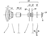
Fig. 1 is the lens sectional view of locating according to the wide-angle side of the zoom-lens system of example 1 of the present invention (short focal length extremity).Fig. 2 A, Fig. 2 B and Fig. 2 C are respectively the aberration diagrams that the wide-angle side according to the zoom-lens system of example 1, middle zoom position and telescope end (long focal length extremity) are located.Fig. 3 is the lens sectional view according to the wide-angle side place of the zoom-lens system of example 2 of the present invention.Fig. 4 A, Fig. 4 B and Fig. 4 C are respectively the aberration diagrams at the wide-angle side according to the zoom-lens system of example 2, middle zoom position and telescope end place.Fig. 5 is the lens sectional view according to the wide-angle side place of the zoom-lens system of example 3 of the present invention.Fig. 6 A, Fig. 6 B and Fig. 6 C are respectively the aberration diagrams at the wide-angle side according to the zoom-lens system of example 3, middle zoom position and telescope end place.Fig. 7 is the lens sectional view according to the wide-angle side place of the zoom-lens system of example 4 of the present invention.Fig. 8 A, Fig. 8 B and Fig. 8 C are respectively the aberration diagrams at the wide-angle side according to the zoom-lens system of example 4, middle zoom position and telescope end place.Fig. 9 is the lens sectional view according to the wide-angle side place of the zoom-lens system of example 5 of the present invention.Figure 10 A, Figure 10 B and Figure 10 C are respectively the aberration diagrams at the wide-angle side according to the zoom-lens system of example 5, middle zoom position and telescope end place.In each example, light path, by being arranged on the inner reflection surface bending in prism, still, for convenient, illustrates the light path in each lens sectional view with the state launched.Figure 11 be according to example 1 of the present invention pass through to be arranged on the crooked light path of inner reflection surface in reflector element (prism) time the lens sectional view.
Figure 12 is the schematic diagram that comprises the major part of the camera (image pick-up device) according to zoom-lens system of the present invention.The zoom-lens system of each example is the capture lens system for the image pick-up device such as video camera, digital camera and silver halide film camera.In the lens sectional view, left side is corresponding with object side (thing side) (the place ahead), and right side is corresponding with picture side (rear).In the lens sectional view, the order of lens unit from the thing side meaned by i, and i lens unit meaned by Li.Zoom-lens system comprises: the rear group of LR that comprises a plurality of lens units; The aperture diaphragm SP of confine optical beam; Solar flare (flare) the diaphragm FP that ends undesirable light; There is inner reflection surface so that crooked 90 degree of light path or about prism (reflector element) PR of 90 degree; With the optical block G corresponding with light filter, panel, crystal low-pass filter, infrared cutoff filter etc.
As image planes IP, when zoom-lens system is used as the photographing optical system of video camera or digital still camera, the imaging surface such as the solid-state image pickup device (photo-electric conversion element) of charge-coupled image sensor (CCD) sensor or complementary metal oxide semiconductor (CMOS) (CMOS) sensor is set.As an alternative, when for the silver halide film camera, using zoom-lens system, the photosensitive surface corresponding with the film surface is set.In aberration diagram, d and g mean respectively d line and g line.Δ M and Δ S mean respectively meridianal image surface and sagittal image surface.Lateral chromatic aberration is expressed by the g line.Symbol " w " means half rink corner (taking the half value (half value) of rink corner), and Fno means the F number.And, in each example described below, wide-angle side and telescope end refer to the zoom position when zoom is positioned at each end of mechanical movable range with lens unit along optical axis.
Zoom-lens system in each example comprises the first lens unit L1 with positive refracting power, the second lens unit L2 with negative refracting power from the object side to image side successively, for the prism PR that makes the light path bending and the rear group of LR that comprises a plurality of lens units.With at the wide-angle side place, compare, the far-end that is visible, first lens unit L1 with respect to imaging surface to the thing side shifting, and the second lens unit L2 with respect to imaging surface to the picture side shifting, to carry out zoom.
In each example, in zoom, and compare at the wide-angle side place, the far-end that is visible, first lens unit L1 moves as more approaching the thing side.Therefore, the lens overall length at wide-angle side place reduces, and reduces thus the front lens effective diameter, and, obtain high zoom ratios.Especially, in each example, there is the first lens unit L1 of positive refracting power to the thing side shifting, make the second lens unit L2 there is large zoom effect.Therefore, in the situation that the refracting power of not many increase first lens unit L1 and the second lens unit L2 obtains approximately 10 high zoom ratios.
First lens unit L1 and the second lens unit L2 amount of movement with respect to image planes in the zoom from the wide-angle side to the telescope end is meaned by M1 and M2 respectively.The focal length of the second lens unit L2 means by f2, and the focal length of the far-end that is visible of whole system is meaned by ft.Then, meet following conditional:
0.1<|M1/M2|<20.0...(1)
0.050<|f2/ft|<0.175...(2)
Wherein, each in rate of travel M1 and M2 is to compare the displacement on optical axis direction (difference position between) of each lens unit of telescope end place about image planes with the wide-angle side place, and, its symbol the thing side for negative and in the picture side for just.
Conditional (1) limits the M1 of the rate of travel with respect to image planes that contributes to zoom in the zoom from the wide-angle side to the telescope end of first lens unit L1 and the second lens unit L2 and the suitable scope of M2, when reducing the front lens diameter, to realize high zoom ratios.Usually, can by increase contribute to zoom lens unit refracting power and obtain angle, wide field and high zoom ratios by increasing amount of movement.But, if refracting power increases too much, becoming so and be difficult to aberration correction, result is to obtain good performance.In addition, if increase the quantity that forms lens for aberration correction, become difficult to achieve so thin camera.And too large if amount of movement is set as, the lens overall length also becomes greatly so, result is the miniaturization that is difficult to realize camera.If the amount of movement M1 of first lens unit L1 and the second lens unit L2 and the ratio between M2 become lower than the lower limit of conditional (1), realize high zoom ratios for the amount of movement with little so, need to increase the refracting power of first lens unit L1.As a result of, the front lens effective diameter increases.In addition, the far-end that mainly is visible of becoming is difficult to correcting spherical aberration and axial chromatic aberration, and is difficult to the positive coma zoom intermediate range lieutenant colonel.In addition, due to the refracting power increase of first lens unit L1, therefore, the inclination of each lens unit/parallel eccentric susceptibility increases.As a result of, due to the bias that the space by mechanical part or gap cause, become and be difficult to obtain good optical property when the assembling camera and in normal the shooting.
The upper limit of greater than condition formula (1) if the amount of movement M1 of first lens unit L1 and the second lens unit L2 and the ratio between M2 become, so, for the amount of movement with little is realized high zoom ratios, need to increase the refracting power of the second lens unit L2.Thereby, become and mainly at the wide-angle side place, be difficult to proofread and correct filed curvature and lateral chromatic aberration, the far-end that is difficult to be visible is proofreaied and correct axial chromatic aberration and be difficult to suppress in whole zooming range at the picture periphery image planes fluctuation.In addition, because the refracting power that mainly contains the second lens unit L2 that helps zoom increases, so the inclination of each lens unit/parallel eccentric susceptibility increases.Therefore, due to the bias that the space by mechanical part or gap cause, become and be difficult to obtain good optical property when the assembling camera and in normal the shooting.And, when the amount of movement M1 of first lens unit L1 increases, image blurringly in zoom, increasing, result is to become to be difficult to obtain good optical property when the taking moving image.
For the suitable ratio that the focal distance f 2 of setting the second lens unit L2 and whole system are visible between the focal distance f t of far-end, qualifications formula (2) to realize high zoom ratios, obtains good optical property simultaneously on whole zooming range.The lower limit lower than conditional (2) with the focal distance f t with respect to whole system if the focal length of the second lens unit L2 diminishes, become so and mainly be difficult to proofread and correct filed curvature and lateral chromatic aberration at the wide-angle side place, and be difficult to suppress in whole zooming range at the picture periphery image planes fluctuation.In addition, because the refracting power that mainly contains the second lens unit L2 that helps zoom increases, so the inclination of each lens unit/parallel eccentric susceptibility increases.As a result of, due to the bias that the space by mechanical part or gap cause, become and be difficult to obtain good optical property when the assembling camera and in normal the shooting.If the focal length of the second lens unit L2 becomes the upper limit that exceeds greatly conditional (2) with the focal distance f t with respect to whole system, so in order to realize that high zoom ratios need to increase the amount of movement of the second lens unit L2.As a result of, the lens overall length increases, and it is large that camera becomes.In addition, the effective diameter of first lens unit and the second lens unit increases, and this is bad.
As mentioned above, the refracting power of the first lens unit L1 at wide-angle side place and telescope end place and the amount of movement of the second lens unit L2 and the second lens unit L2 is suitably set, and makes the formula of satisfying condition (1) and (2).Therefore, provide the little zoom-lens system that there is high zoom ratio and little front lens effective diameter, keeps high optical property simultaneously on whole zooming range.
Note, more preferably the numerical range of conditional (1) and (2) is set as follows.
0.2<|M1/M2|<15.0···(1a)
0.100<|f2/ft|<0.175···(2a)
More preferably conditional (1a) and numerical range (2a) are set as follows.
0.36<|M1/M2|<12.00···(1b)
0.120<|f2/ft|<0.170···(2b)
By above-mentioned structure, can obtain and there is angle, wide field and high zoom ratio and the little zoom-lens system that there is high optical property on whole zooming range.
In the present invention, one or more in more preferably meeting the following conditions.The focal length of first lens unit L1 is meaned by f1.Whole system is meaned by fw at the focal length at wide-angle side place.The second lens unit L2 is meaned by β 2w and β 2t respectively in the horizontal multiplying power at wide-angle side place and telescope end place.
The interval of the telescope end between the second lens unit L2 and the 3rd mobile lens unit (the 3rd mobile lens unit is the 3rd mobile unit of counting from the thing side and moves for zoom) is meaned by DM23t.The focal length of the 3rd mobile lens unit (the 3rd mobile lens unit is the 3rd mobile unit of counting from the thing side and moves for zoom) is meaned by fM3.Then, preferably meet one or more in following conditional.
4.5<f1/fw<10.0···(3)
3.0<β2t/β2w<6.0···(4)
0.02<M2/ft<0.20···(5)
1.0<DM23t/fw<10.0···(6)
0.1<|f2/f
M3|<0.6···(7)
Conditional (3) limits focal distance f 1 and the suitable ratio of whole system between the focal distance f w at wide-angle side place of first lens unit L1, to reduce the size of whole system, realizes high zoom ratio simultaneously.If the focal distance f 1 of first lens unit L1 become too little with respect to whole system at the focal distance f w at wide-angle side place the lower limit lower than conditional (3), become so and mainly be difficult to proofread and correct at the wide-angle side place lateral chromatic aberration when realizing the angle, wide field.In addition, when realizing high zoom ratios, axial chromatic aberration and the lateral chromatic aberration far-end that is visible increases.In addition, become and be difficult to guarantee form the edge thickness of the positive lens of first lens unit L1.As a result of, in order to manufacture, need to increase effective diameter, and the front lens effective diameter increases, this is bad.And, in assembling process, the eccentric susceptibility of first lens unit L1 increases, thereby causes deteriorated optical property, this is bad.If the focal distance f of first lens unit L1 1 becomes greatly so that with respect to whole system, the focal distance f w at the wide-angle side place exceeds the upper limit of conditional (3), when realizing high zoom ratios, the amount of movement of first lens unit L1 increases in zoom operation so.Therefore, whole system becomes large.In addition, become and be difficult to be visible the far-end correcting spherical aberration.In addition, the amount of movement of first lens unit L1 increases in zoom operation, thus the image blurring increase in zoom.As a result of, become and be difficult to obtain good optical property when the taking moving image.
In order in whole system hour, to obtain high zoom ratios, conditional (4) limits suitable horizontal multiplying power β 2w and the β 2t of the second lens unit L2 at wide-angle side place and telescope end place.If the horizontal multiplying power β 2w of the second lens unit L2 at wide-angle side place is the lower limit lower than conditional (4) with the horizontal multiplying power β 2t with respect to the telescope end place too greatly, the mobile quantitative change of the second lens unit L2 in zoom is large so.Therefore, the lens overall length is increased to large size, and this is bad.If becoming too little, the horizontal multiplying power β 2w of the second lens unit L2 at wide-angle side place is difficult in whole zooming range colonel positive coma and image planes fluctuation to compare with the horizontal multiplying power β 2t at telescope end place the higher limit that exceeds conditional (4), to become so.In addition, because the front lens effective diameter increases, therefore become difficult to achieve the miniaturization of whole system.
In order in whole system hour, to obtain high zoom ratios, conditional (5) limits the suitable ratio that the amount of movement M2 of the second lens unit L2 in zoom and whole system are visible between the focal distance f t of far-end.If the amount of movement M2 of the second lens unit L2 is too little of with the be visible focal distance f t of far-end of whole system, to compare the lower limit lower than conditional (5), so, in order to realize high zoom ratio, must increase the refracting power that mainly contains the second lens unit L2 that helps zoom.As a result of, become and mainly be difficult to proofread and correct filed curvature and lateral chromatic aberration at the wide-angle side place, and be difficult to suppress in whole zooming range at the picture periphery image planes fluctuation.In addition, the inclination of each lens unit/parallel eccentric susceptibility increases.As a result of, due to the bias that the space by mechanical part or gap cause, therefore become and be difficult to obtain good optical property when the assembling camera and in normal the shooting.Compare if the amount of movement M2 of the second lens unit L2 becomes the large focal distance f t with the far-end that is visible with whole system the upper limit that exceeds conditional (5), so in order to realize high zoom ratios, the lens overall length increases, thereby causes the size of whole camera large.In addition, the effective diameter of first lens unit and the second lens unit increases, and this is bad.
In order in whole system hour, to obtain high zoom ratio, the second mobile lens unit L2 that conditional (6) restriction is counted from the thing side and the distance B M23t on optical axis and the suitable ratio of whole system at the focal distance f w at wide-angle side place of the telescope end between the 3rd mobile lens unit LM3.Wherein, the 3rd mobile lens unit LM3 and the 4th lens unit L4 in example 1~3, the 3rd lens unit L3 and the 3rd lens unit L3 in example 5 in example 4 are corresponding.Be less than whole system at the focal distance f w at wide-angle side place and, lower than the lower limit of conditional (6), the vignetting (vignetting) of peripheral light amount occur so due to the prism for crooked light path if the distance B M23t on optical axis of the telescope end between the second mobile lens unit L2 of counting from the thing side and the 3rd mobile lens unit LM3 becomes.As a result of, become and be difficult to obtain good optical property.If the distance B M23t on the optical axis of the telescope end between the second mobile lens unit of counting from the thing side and the 3rd mobile lens unit becomes, the focal distance f w at the wide-angle side place than whole system exceeds greatly the upper limit of conditional (6), and the lens overall length increases so.As a result of, become difficult to achieve the miniaturization of whole system.In addition, in order to obtain high zoom ratios, must increase the refracting power of the second mobile lens unit L2 and the 3rd mobile lens unit LM3.As a result of, the inclination of each lens unit/parallel eccentric susceptibility increases.As a result of, due to the bias that the space by mechanical part or gap cause, become and be difficult to obtain good optical property when the assembling camera and in normal the shooting.
In order in whole system hour, to obtain high zoom ratio, conditional (7) limits the second mobile lens unit L2 and the focal distance f 2 of the 3rd mobile lens unit LM3 and the suitable ratio between fM3 of counting from the thing side.Mainly be difficult to proofread and correct filed curvature and lateral chromatic aberration at the wide-angle side place to compare the lower limit lower than conditional (7) with focal distance f M3, to become so if focal distance f 2 is too little, and be difficult to suppress in whole zooming range at the picture periphery image planes fluctuation.In addition, by prism, make light path bending lens overall length afterwards elongated, result is the miniaturization that becomes difficult to achieve camera.And the inclination of each lens unit/parallel eccentric susceptibility increases.As a result of, due to the bias that the space by mechanical part or gap cause, therefore become and be difficult to obtain good optical property when the assembling camera and in normal the shooting.If focal distance f 2 becomes too greatly with focal distance f M3, to compare the upper limit that exceeds conditional (7), so, in order to obtain high zoom ratios, the lens overall length is elongated, and becomes difficult to achieve thus the miniaturization of camera.
Note, in order further in the miniaturization that realizes whole lens combination, to reduce the aberration fluctuation in aberration correction and zoom operation, preferably the numerical range of conditional (3)~(6) is set as follows.
4.6<f1/fw<9.0···(3a)
3.0<β2t/β2w<5.0···(4a)
0.04<M2/ft<0.18···(5a)
1.5<DM23t/fw<6.0···(6a)
0.20<|f2/f
M3|<0.55···(7a)
In each example, in order to reduce the effective lens diameter of first lens unit L1, the quantity that forms the lens of first lens unit L1 is set to few as much as possible.In each example, first lens unit L1 comprises negative lens, positive lens and positive lens (three lens) from the object side to image side successively.
Especially, first lens unit L1 comprises balsaming lens (in this balsaming lens, positive lens and negative lens are glued together) and positive lens.Therefore, the spherical aberration occurred when realizing high zoom ratios and aberration are suitably proofreaied and correct.
The second lens unit L2 in each example has one or more non-spherical surface.Especially, in each example, the one or both sides of the lens that approach the thing side most in the second lens unit L2 form non-spherical surface.Therefore, mainly in the lateral chromatic aberration of wide-angle side and the filed curvature in whole zooming range, suitably proofreaied and correct.
Example 1~3 shown in Fig. 1, Fig. 3 and Fig. 5 is described now.In the lens sectional view of example 1~3, the first lens unit with positive refracting power is meaned by L1, and the second lens unit with negative refracting power is meaned by L2.Rear group of LR comprise the 3rd lens unit L3, the 4th lens unit L4 with positive refracting power with negative refracting power, have the 5th lens unit L5 of negative refracting power and have the 6th lens unit L6 of positive refracting power.Six unit zoom-lens systems are described in example 1~3.For the zoom from the wide-angle side to the telescope end, first lens unit L1, the second lens unit L2, the 4th lens unit L4 and the 6th lens unit L6 movement as arrow means.
Especially, for the zoom from the wide-angle side to the telescope end, with respect to image planes, first lens unit L1 is to the thing side shifting, and the second lens unit L2 is to the picture side shifting, and the 4th lens unit L4 is to the thing side shifting.Therefore, when realizing high zoom ratios, the zoom of the second lens unit L2 burden reduces, and the second lens unit L2 is miniaturized, with the thickness of the whole camera that reduces to apply zoom-lens system.In addition, the filed curvature in whole zooming range reduces, and obtains high optical property on whole zooming range simultaneously.In the track with two flex points, the 6th lens unit L6 is to the picture side shifting, then to the thing side shifting, and then to the picture side shifting.In addition, adopt in order to focus on the back focus type of mobile the 6th lens unit L6 on optical axis.Therefore, with the situation for focusing on the front group (first lens unit L1 and the second lens unit L2) of use, compare, whole system is miniaturized.
When the far-end that is visible is carried out the focusing from the infinity object to closer object, as shown in arrow 6c, the 6th lens unit L6 is sent the place ahead.Block curve 6a and dashed curve 6b about the 6th lens unit L6 mean respectively for proofread and correct the motion track of the image planes fluctuation caused due to the zoom from the wide-angle side to the telescope end when on the infinity object and on closer object, carrying out focusing.In addition, in example 1~3, for focusing on, can use the 5th lens unit L5 with negative refracting power.In this case, by being passed out to back, the 5th lens unit L5 carries out the focusing from the infinity object to closer object.
In example 1~3, prism PR, the 3rd lens unit L3 and the 5th lens unit L5 do not move for zoom.Note, the 3rd lens unit L3 and the 5th lens unit L5 can move for zoom is independent of other lens unit ground as required.Each in the 3rd lens unit L3 and the 5th lens unit L5 consists of single negative lens, makes the lens overall length reduce and whole system is miniaturized.The 4th lens unit L4 at least comprises a negative lens and two positive lenss, makes and suitably carries out aberration correction.
Especially, the 4th lens unit L4 comprises positive lens, negative lens and balsaming lens (in this balsaming lens, positive lens and negative lens are glued together) from the object side to image side successively.Therefore, the spherical aberration in whole zooming range and coma aberration and the coma aberration and the lateral chromatic aberration that cause due to the bias in anti-shake operation are suitably proofreaied and correct.In addition, the 4th lens unit L4 has one or more non-spherical surface.The fluctuation of the spherical aberration therefore, caused due to zoom is suitably proofreaied and correct.In example 1 and example 2, in the 4th lens unit L4, aperture diaphragm SP is set, and the 4th lens unit L4 as side, solar flare diaphragm FP is set, and two diaphragms integrally move for zoom and the 4th lens unit L4.In example 3, aperture diaphragm SP is arranged on the thing side of the 4th lens unit L4 and moves independently for zoom.Solar flare diaphragm FP is arranged on integrally moving with the 4th lens unit L4 as side and for zoom of the 4th lens unit L4.
In example 1~3, part or all of the 4th lens unit L4 with positive refracting power moves to have the composition along the direction vertical with optical axis, makes thus image along the direction displacement vertical with optical axis.Therefore, the fuzzy of photographic images caused due to the shake (inclination) of whole optical system (zoom-lens system) is corrected, and result is to obtain good optical property.Note, as part or all substitute of the 4th lens unit L4, the 5th lens unit L5 is removable to have along the composition of the direction vertical with optical axis, fuzzy with correcting captured image.
In this example and following each example, in the situation that newly do not add such as the optics of variable angle prism or carry out anti-shake operation for the lens unit of anti-shake operation, to prevent whole optical system, become large.Note, in this example and following each example, all or part of of lens unit moves along the direction vertical with optical axis for anti-shake operation, still, and can be fuzzy to have along the correcting image that becomes to assign to of the direction vertical with optical axis by all or part of of mobile lens unit.For example, if allow the complicated of lens barrel structure, so can be for anti-shake operation relay lens unit all or part of (rotation center is on optical axis).
Example 4 shown in Fig. 7 is described.In the lens sectional view of example 4, the first lens unit with positive refracting power is meaned by L1, and the second lens unit with negative refracting power is meaned by L2.Rear group of LR comprises the 3rd lens unit L3 with positive refracting power and the 4th lens unit L4 with positive refracting power.Four unit zoom-lens systems are described in example 4.For the zoom from the wide-angle side to the telescope end, first lens unit L1, the second lens unit L2, the 3rd lens unit L3 and the 4th lens unit L4 movement as arrow means.Especially, for the zoom from the wide-angle side to the telescope end, first lens unit L1 is to the thing side shifting, and the second lens unit L2 is to the picture side shifting, and the 3rd lens unit L3 is to the thing side shifting.The second lens unit L2, to the picture side shifting, makes and carries out main zoom.And the 4th lens unit L4 moves to have the track towards thing side projection, to proofread and correct the image planes fluctuation caused due to zoom.In addition, carry out and focus on by the 4th lens unit L4.Due to the motion track of the 4th lens unit L4, towards thing side projection, therefore the space between the 3rd lens unit L3 and the 4th lens unit L4 is effectively used, and can effectively reduce the lens overall length thus.
Block curve 4a and dashed curve 4b about the 4th lens unit L4 mean respectively for proofread and correct the motion track of the image planes fluctuation caused due to zoom when on the infinity object and on closer object, carrying out focusing.In addition, when the far-end that is visible is carried out the focusing from the infinity object to closer object, the 4th lens unit L4 is meaned by arrow 4c is sent the place ahead like that.In example 4, prism PR does not move for zoom.Aperture diaphragm SP is arranged in the 3rd lens unit L3, and solar flare diaphragm FP is arranged on the picture side of the 3rd lens unit L3, and two diaphragms integrally move with the 3rd lens unit L3 in zoom operation.In example 4, part or all of the 3rd lens unit L3 moves to have the composition along the direction vertical with optical axis, makes thus image along the direction displacement vertical with optical axis.Therefore, the fuzzy of photographic images caused due to the shake (inclination) of whole optical system (zoom-lens system) is corrected, and result is to obtain good optical property.
The 3rd lens unit L3 at least comprises a negative lens and two positive lenss and makes and suitably carry out aberration correction.Especially, the 3rd lens unit L3 comprises positive lens, negative lens and balsaming lens (in this balsaming lens, positive lens and negative lens are glued together).Therefore, the spherical aberration in whole zooming range and coma aberration and the coma aberration and the lateral chromatic aberration that cause due to the bias in anti-shake operation are suitably proofreaied and correct.The 3rd lens unit L3 has one or more non-spherical surface.The fluctuation of the spherical aberration therefore, caused due to zoom is suitably proofreaied and correct.
Example 5 shown in Fig. 9 is described.In the lens sectional view of example 5, the first lens unit with positive refracting power is meaned by L1, and the second lens unit with negative refracting power is meaned by L2.Rear group of LR comprise the 3rd lens unit L3 with positive refracting power, have the 4th lens unit L4 of negative refracting power and have the 5th lens unit L5 of positive refracting power.Five unit zoom-lens systems are described in example 5.In example 5, for the zoom from the wide-angle side to the telescope end, first lens unit L1, the second lens unit L2, the 3rd lens unit L3 and the 5th lens unit L5 movement as arrow means.Therefore, the zoom of the second lens unit is partly shared, and result is when realizing high zoom ratios, to make the second lens unit thin and reduce camera thickness.In addition, the filed curvature in whole zooming range is corrected, and result is to obtain good optical property.
In example 5, as shown by arrows, with respect to image planes, for the zoom from the wide-angle side to the telescope end, first lens unit L1 is to the thing side shifting, and the second lens unit L2 is to the picture side shifting, and the 3rd lens unit L3 is to the thing side shifting.In the track with two flex points, the 5th lens unit L5 for zoom to the picture side shifting, then to the thing side shifting, and then to the picture side shifting.Employing is in order to focus on the back focus type of mobile the 5th lens unit L5 on optical axis.Therefore, block curve 5a and the dashed curve 5b about the 5th lens unit L5 means respectively for proofread and correct the motion track of the image planes fluctuation caused due to the zoom from the wide-angle side to the telescope end when on the infinity object and on closer object, carrying out focusing.
In each example, for example, when the far-end that is visible is carried out the focusing from the infinity object to closer object, the 5th lens unit L5 is sent the place ahead as arrow 5c means.In addition, can carry out and focus on by the 4th lens unit L4 with negative refracting power.In this case, by being passed out to rear, the 4th lens unit L4 carries out the focusing from the infinity object to closer object.Aperture diaphragm SP is arranged in the 3rd lens unit L3, and solar flare diaphragm FP is arranged on the picture side of the 3rd lens unit L3, and these two diaphragms integrally move with the 3rd lens unit L3 in zoom operation.In example 5, prism PR and the 4th lens unit L4 do not move for zoom.Note, for the 4th lens unit L4 of zoom, can be independent of as required other lens unit ground movement.In example 5, the 3rd lens unit L3 moves to have the composition along the direction vertical with optical axis, makes thus image along the direction displacement vertical with optical axis.Therefore, the fuzzy of photographic images caused due to the shake (inclination) of whole optical system (zoom-lens system) is corrected, and makes and obtains good optical property.In example 5, the 4th lens unit L4 is used in the shake of the shooting rink corner that can cause for the vibration of proofreading and correct due to zoom-lens system.The 3rd lens unit L3 at least comprises a negative lens and two positive lenss, and result is suitably to carry out aberration correction.Especially, the 3rd lens unit L3 comprises positive lens, negative lens and balsaming lens (in this balsaming lens, positive lens and negative lens are glued together).
Therefore, the spherical aberration in whole zooming range and coma aberration and the coma aberration and the lateral chromatic aberration that cause due to the bias in anti-shake operation are suitably proofreaied and correct.The 3rd lens unit L3 has one or more non-spherical surface.The fluctuation of the spherical aberration therefore, caused due to zoom is suitably proofreaied and correct.In example 5, the 4th lens unit L4 consists of single negative lens.Therefore, reduce the lens overall length, and realize thus the miniaturization of camera.The 5th lens unit L5 consists of single positive lens.According to each example, by above-mentioned structure, can provide the size of whole optical system little, there is approximately 10 high zoom ratios and the zoom-lens system that there is high optical property on whole zooming range.In addition, because the zoom-lens system of each example comprises for bending the reflection of light parts PR from the thing side as shown in Figure 11 between the second lens unit L2 and the 3rd lens unit L3, therefore, can easily reduce the size of the thickness direction of camera.
The Reference numeral of the expression parts in Figure 11 is with shown in the drawings those are identical.Then, in each example, with reference to Figure 12, describe and use the digital still camera as photographing optical system according to the zoom-lens system of each example.In example 12, digital still camera comprises camera body 20 and any photographing optical system formed 21 in the zoom-lens system of describing in example 1~5.Digital still camera also comprises camera body 20 and any photographing optical system formed 21 in the above zoom-lens system of describing in example 1~5.PR refers to prism.Digital still camera also comprises the solid-state image pickup device such as ccd sensor or cmos sensor (photo-electric conversion element) 22 of the image that is merged in the subject formed by photographing optical system 21 for reception in camera body.Digital still camera also comprises the storer 23 of the information corresponding with the image of the subject that has been performed opto-electronic conversion by solid-state image pickup device 22 for record.Digital still camera also comprises the view finder 24 for the image of observing the subject formed on solid-state image pickup device 22 consisted of display panels etc.By this way, by use be used for such as the image pick-up device of digital still camera according to zoom-lens system of the present invention, the pick device of the small-sized image with high optical property can be provided.
Corresponding with example 1~5 of the present invention respectively numerical example 1~5 is described below.In each numerical example, i means the order of the optical surface counted from the thing side, ri means the radius-of-curvature on i optical surface (i surface), di means the distance between i surface and (i+1) individual surface, and ndi and vdi mean respectively about the refractive index of the material of i optics of d line and Abbe number.In addition, k means degree of eccentricity (eccentricity), and A4, A6, A8 and A10 mean asphericity coefficient, and the position that is h apart from the optical axis height is meaned by x about the displacement along optical axis direction of surface vertices.Then, aspherical shape is expressed by following formula.
X=(h
2/ R)/[1,+[1 mono-(1+k) is (h/R)
2]
1/2]+A4h
4+ A6h
6+ A8h
8
Wherein, R means the paraxonic radius-of-curvature.In addition, for example, expression way " E-Z " means 10
-Z.Latter two surface in numerical example is the surface such as the optical block of wave filter, panel etc.In each example, back focal length (BF) means the distance as the air characteristic chamber length between lens end surfaces and paraxonic image planes.The lens overall length is to approach the surface of thing side most and the distance between last surface adds back focal length.In addition, the corresponding relation between each numerical example shown in table 1 and above-mentioned conditional.
Numerical example 1
Unit: mm
Surface data


The non-spherical surface data
The 7th surface
K=-1.71269e-001 A4=-2.50781e-005
The 16 surface
K=-1.71698e+000 A4=9.69184e-005 A6=-1.01040e-006 A8=1.76003e-008
The 17 surface
K=1.79790e+001 A4=5.87754e-006
The 21 surface
K=6.18823e+000 A4=-7.36522e-005
Various data
Zoom ratio 9.50

The Zoom lens unit data

Numerical example 2
Unit: mm
Surface data


The non-spherical surface data
The 7th surface
K=-1.28711e-001 A4=-1.40311e-005 A6=-4.83079e-007
The 16 surface
K=-6.09172e-001 A4=-3.96922e-005 A6=2.92135e-008 A8=-1.13412e-009
The 17 surface
K=-6.89933e-001 A4=2.56587e-005
Various data
Zoom ratio 9.48

The Zoom lens unit data

Numerical example 3
Unit: mm
Surface data


The non-spherical surface data
The 7th surface
K=-6.21150e-002 A4=-1.25254e-004 A6=-3.37844e-006 A8=-8.30551e-008
The 17 surface
K=-5.18633e-001 A4=-4.18160e-005 A6=3.45532e-007 A8=7.52442e-009
The 18 surface
K=-4.99082e+000 A4=8.48305e-005
Various data
Zoom ratio 9.49
The Zoom lens unit data

Numerical example 4
Unit: mm
Surface data


The non-spherical surface data
The 7th surface
K=-1.65329e-001 A4=-1.83577e-005
The 14 surface
K=-2.27427e+000 A4=1.12081e-004 A6=-9.48568e-007 A8=-6.99943e-008
The 15 surface
K=4.80045e+001 A4=-4.22357e-005
The 19 surface
K=2.82756e+001 A4=-2.53664e-005
Various data
Zoom ratio 9.50

The Zoom lens unit data

Numerical example 5
Unit: mm
Surface data


The non-spherical surface data
The 7th surface
K=-2.56130e-002 A4=-4.70562e-005
The 14 surface
K=-1.56620e+000 A4=1.20103e-004 A6=-1.26808e-006 A8=5.13438e-008
The 15 surface
K=2.00477e+001 A4=4.31458e-005
The 19 surface
K=1.11736e+001 A4=-6.85687e-005
Various data

The Zoom lens unit data

Table 1
| Conditional | Example 1 | Example 2 | Example 3 | Example 4 | Example 5 |
| (1)0.1<|M1/M2|<20.0 | 2.005 | 0.451 | 7.233 | 2.073 | 1.825 |
| (2)0.050<|f2/ft|<0.175 | 0.149 | 0.140 | 0.163 | 0.128 | 0.127 |
| (3)4.5<f1/fw<10.0 | 6.114 | 4.869 | 8.095 | 5.714 | 5.909 |
| (4)3.0<β2t/β2w<6.0 | 3.839 | 4.210 | 3.559 | 4.725 | 3.488 |
| (5)0.02<M2/ft<0.20 | 0.102 | 0.163 | 0.052 | 0.099 | 0.103 |
| (6)1.0<DM23t/fw<10.0 | 2.197 | 1.809 | 3.220 | 1.833 | 1.849 |
| (7)0.1<|f2/f3|<0.6 | 0.512 | 0.379 | 0.465 | 0.375 | 0.421 |
Although with reference to exemplary embodiment, the present invention has been described, has should be understood that and the invention is not restricted to disclosed exemplary embodiment.The scope of following claim should be endowed the widest explanation to comprise all modifications and the 26S Proteasome Structure and Function be equal to.
Claims (15)
1. a zoom-lens system comprises from the object side to image side successively:
First lens unit with positive refracting power;
The second lens unit with negative refracting power;
Prism for crooked light path; With
Comprise a plurality of lens units rear group,
Wherein, and compare at the wide-angle side place, the far-end that is visible, with respect to imaging surface, the first lens unit is to the thing side shifting, and the second lens unit is to the picture side shifting, and meet following conditional:
0.1<|M1/M2|<20.0
0.050<|f2/ft|<0.175
1.809≤DM23t/fw<10.0,
Wherein, M1 and M2 mean respectively first lens unit and the second lens unit amount of movement with respect to image planes in the zoom from the wide-angle side to the telescope end, f2 means the focal length of the second lens unit, DM23t mean the second lens unit and the lens unit of the 3rd setting of counting from the thing side among mobile lens unit for zoom between the optical axis of telescope end on interval, fw means the focal length at the wide-angle side place of whole system, and ft means the focal length of the far-end that is visible of whole system.
2. according to the zoom-lens system of claim 1, wherein, meet following conditional:
4.5<f1/fw<10.0,
Wherein, f1 means the focal length of first lens unit.
3. according to the zoom-lens system of claim 1, wherein, meet following conditional:
3.0<β2t/β2w<6.0,
Wherein, β 2w and β 2t mean respectively the horizontal multiplying power at wide-angle side place and the telescope end place of the second lens unit.
4. according to the zoom-lens system of claim 1, wherein, meet following conditional:
0.02<M2/ft<0.2。
5. according to the zoom-lens system of claim 1, wherein, meet following conditional:
0.1<|f2/fM3|<0.6,
The focal length of the lens unit of the 3rd setting of counting from the thing side among the lens unit that wherein, fM3 means to move for zoom.
6. according to the zoom-lens system of claim 1,
Wherein, described rear group comprises successively from the object side to image side the 3rd lens unit, the 4th lens unit with positive refracting power with negative refracting power, has the 5th lens unit of negative refracting power and has the 6th lens unit of positive refracting power, and,
Wherein, the 3rd lens unit and the 5th lens unit do not move for zoom, and the 4th lens unit and the 6th lens unit move for zoom.
7. according to the zoom-lens system of claim 6, wherein, the 3rd lens unit comprises single negative lens.
8. according to the zoom-lens system of claim 6, wherein, the 5th lens unit comprises single negative lens.
9. according to the zoom-lens system of claim 6, wherein, the 4th lens unit moves to have the composition along the direction vertical with optical axis direction, and the fuzzy of photographic images that makes the shake due to zoom-lens system cause is corrected.
10. according to the zoom-lens system of claim 1,
Wherein, described rear group comprises the 3rd lens unit with positive refracting power and the 4th lens unit with positive refracting power from the object side to image side successively, and,
Wherein, the 3rd lens unit and the 4th lens unit move for zoom.
11. according to the zoom-lens system of claim 1,
Wherein, described rear group comprises successively from the object side to image side the 3rd lens unit with positive refracting power, has the 4th lens unit of negative refracting power and has the 5th lens unit of positive refracting power, and,
Wherein, the 4th lens unit does not move for zoom, and the 3rd lens unit and the 5th lens unit move for zoom.
12., according to the zoom-lens system of claim 11, wherein, the 4th lens unit comprises single negative lens.
13., according to the zoom-lens system of claim 10, wherein, the 3rd lens unit moves to have along the composition of the direction vertical with optical axis direction, the fuzzy of photographic images that makes the shake due to zoom-lens system cause is corrected.
14., according to the zoom-lens system of claim 1, wherein, form image on solid-state image pickup device.
15. an image pick-up device comprises:
Zoom lens; With
Imageing sensor, described imageing sensor is configured to receive the image formed by described zoom lens;
Wherein, described zoom lens comprise from the object side to image side successively:
First lens unit with positive refracting power;
The second lens unit with negative refracting power;
Prism for crooked light path; With
Comprise a plurality of lens units rear group,
Wherein, and compare at the wide-angle side place, the far-end that is visible, with respect to imaging surface, the first lens unit is to the thing side shifting, and the second lens unit is to the picture side shifting, and meet following conditional:
0.1<|M1/M2|<20.0
0.050<|f2/ft|<0.175
1.809≤DM23t/fw<10.0,
Wherein, M1 and M2 mean respectively first lens unit and the second lens unit amount of movement with respect to image planes in the zoom from the wide-angle side to the telescope end, f2 means the focal length of the second lens unit, DM23t mean the second lens unit and the lens unit of the 3rd setting of counting from the thing side among mobile lens unit for zoom between the optical axis of telescope end on interval, fw means the focal length at the wide-angle side place of whole system, and ft means the focal length of the far-end that is visible of whole system.
Applications Claiming Priority (2)
| Application Number | Priority Date | Filing Date | Title |
|---|---|---|---|
| JP2010163029A JP5645520B2 (en) | 2010-07-20 | 2010-07-20 | Zoom lens and imaging apparatus having the same |
| JP2010-163029 | 2010-07-20 |
Publications (2)
| Publication Number | Publication Date |
|---|---|
| CN102338928A CN102338928A (en) | 2012-02-01 |
| CN102338928B true CN102338928B (en) | 2013-12-11 |
Family
ID=45493410
Family Applications (1)
| Application Number | Title | Priority Date | Filing Date |
|---|---|---|---|
| CN2011101976949A Expired - Fee Related CN102338928B (en) | 2010-07-20 | 2011-07-15 | Zoom lens system and image pickup apparatus including the same |
Country Status (3)
| Country | Link |
|---|---|
| US (1) | US8649105B2 (en) |
| JP (1) | JP5645520B2 (en) |
| CN (1) | CN102338928B (en) |
Families Citing this family (17)
| Publication number | Priority date | Publication date | Assignee | Title |
|---|---|---|---|---|
| JP5730138B2 (en) | 2011-06-10 | 2015-06-03 | キヤノン株式会社 | Zoom lens and imaging apparatus having the same |
| JP5773793B2 (en) * | 2011-08-04 | 2015-09-02 | キヤノン株式会社 | Zoom lens and imaging apparatus having the same |
| JP5787716B2 (en) * | 2011-10-24 | 2015-09-30 | キヤノン株式会社 | Zoom lens and imaging apparatus having the same |
| JP5893422B2 (en) * | 2012-02-06 | 2016-03-23 | キヤノン株式会社 | Zoom lens and imaging apparatus having the same |
| JP5973252B2 (en) * | 2012-06-22 | 2016-08-23 | 株式会社タムロン | Zoom lens and image pickup apparatus including the same |
| JP6004840B2 (en) * | 2012-08-29 | 2016-10-12 | キヤノン株式会社 | Zoom lens and imaging apparatus having the same |
| JP6016530B2 (en) * | 2012-08-29 | 2016-10-26 | キヤノン株式会社 | Imaging device |
| JP6021534B2 (en) * | 2012-09-04 | 2016-11-09 | キヤノン株式会社 | Zoom lens and imaging apparatus having the same |
| JP5592925B2 (en) | 2012-11-28 | 2014-09-17 | オリンパスイメージング株式会社 | Zoom lens and image pickup apparatus including the same |
| TWI476442B (en) * | 2013-02-26 | 2015-03-11 | Sintai Optical Shenzhen Co Ltd | Zoom lens |
| JP6327842B2 (en) * | 2013-12-06 | 2018-05-23 | キヤノン株式会社 | Zoom lens and imaging apparatus having the same |
| US9557627B2 (en) * | 2014-03-07 | 2017-01-31 | Apple Inc. | Folded camera lens systems |
| US9316810B2 (en) | 2014-03-07 | 2016-04-19 | Apple Inc. | Folded telephoto camera lens system |
| JP6490799B2 (en) * | 2015-03-27 | 2019-03-27 | オリンパス株式会社 | Zoom lens and image pickup apparatus including the same |
| EP3422065A1 (en) * | 2017-06-28 | 2019-01-02 | Gensight Biologics | Objective, camera and system adapted for optogenetics comprising such objective |
| CN111505807B (en) * | 2020-06-30 | 2020-12-01 | 嘉兴中润光学科技有限公司 | High-definition camera and foldback type zoom optical lens |
| US12038622B2 (en) * | 2022-11-11 | 2024-07-16 | Samsung Electro-Mechanics Co., Ltd. | Optical imaging system |
Family Cites Families (18)
| Publication number | Priority date | Publication date | Assignee | Title |
|---|---|---|---|---|
| JP2963520B2 (en) * | 1990-10-18 | 1999-10-18 | オリンパス光学工業株式会社 | Zoom lens with short overall length |
| JP2909765B2 (en) * | 1990-08-24 | 1999-06-23 | オリンパス光学工業株式会社 | Zoom lens with short overall length |
| JP3352240B2 (en) * | 1994-08-05 | 2002-12-03 | キヤノン株式会社 | High zoom ratio zoom lens |
| JP4545849B2 (en) * | 1999-08-27 | 2010-09-15 | キヤノン株式会社 | Variable magnification optical system |
| JP4865137B2 (en) * | 2001-02-13 | 2012-02-01 | キヤノン株式会社 | Zoom lens and optical apparatus using the same |
| JP4564625B2 (en) * | 2000-05-11 | 2010-10-20 | キヤノン株式会社 | Zoom lens and optical apparatus using the same |
| JP4532916B2 (en) * | 2004-01-30 | 2010-08-25 | キヤノン株式会社 | Zoom lens and imaging apparatus having the same |
| JP3960334B2 (en) * | 2004-12-20 | 2007-08-15 | コニカミノルタフォトイメージング株式会社 | Imaging optical system and imaging apparatus |
| JP2007025123A (en) | 2005-07-14 | 2007-02-01 | Konica Minolta Photo Imaging Inc | Variable power optical system |
| JP4881035B2 (en) * | 2006-02-27 | 2012-02-22 | キヤノン株式会社 | Zoom lens and imaging apparatus having the same |
| JP2007279541A (en) * | 2006-04-11 | 2007-10-25 | Olympus Imaging Corp | Bending variable power optical system |
| JP5096011B2 (en) | 2007-02-02 | 2012-12-12 | オリンパス株式会社 | Imaging optical system and electronic imaging apparatus having the same |
| JP5027018B2 (en) * | 2008-03-12 | 2012-09-19 | 富士フイルム株式会社 | Zoom lens and imaging device |
| JP5178322B2 (en) * | 2008-05-26 | 2013-04-10 | キヤノン株式会社 | Zoom lens and imaging apparatus having the same |
| JP5359025B2 (en) * | 2008-05-26 | 2013-12-04 | コニカミノルタ株式会社 | Zoom lens |
| JP5241377B2 (en) * | 2008-08-19 | 2013-07-17 | キヤノン株式会社 | Zoom lens and imaging apparatus having the same |
| JP5511274B2 (en) * | 2008-11-19 | 2014-06-04 | キヤノン株式会社 | Zoom lens and camera having the same |
| JP4790052B2 (en) * | 2009-08-31 | 2011-10-12 | キヤノン株式会社 | Zoom lens and imaging apparatus having the same |
-
2010
- 2010-07-20 JP JP2010163029A patent/JP5645520B2/en not_active Expired - Fee Related
-
2011
- 2011-07-15 CN CN2011101976949A patent/CN102338928B/en not_active Expired - Fee Related
- 2011-07-20 US US13/186,960 patent/US8649105B2/en not_active Expired - Fee Related
Also Published As
| Publication number | Publication date |
|---|---|
| JP5645520B2 (en) | 2014-12-24 |
| CN102338928A (en) | 2012-02-01 |
| US20120019929A1 (en) | 2012-01-26 |
| US8649105B2 (en) | 2014-02-11 |
| JP2012027084A (en) | 2012-02-09 |
Similar Documents
| Publication | Publication Date | Title |
|---|---|---|
| CN102338928B (en) | Zoom lens system and image pickup apparatus including the same | |
| CN102445747B (en) | Zoom lens and image pickup apparatus equipped with same | |
| CN102401985B (en) | Zoom lens and image pickup apparatus having same | |
| CN101988987B (en) | Zoom lens and image pickup apparatus including the same | |
| CN103885161B (en) | Imaging optical system and the image pick up equipment comprising this imaging optical system | |
| CN101750719B (en) | Zoom lens and image pickup apparatus including the same | |
| CN101315458B (en) | Zoom lens and image pick-up apparatus including the zoom lens | |
| CN103454755B (en) | Zoom lens and be furnished with the image pick-up device of these zoom lens | |
| CN105739071A (en) | Zoom Lens And Image Pickup Apparatus Including The Same | |
| CN102955229B (en) | Zoom lens and be furnished with the image pick up equipment of zoom lens | |
| CN103116214A (en) | Zoom lens and image pickup apparatus including the same | |
| CN102914855B (en) | Zoom lens and image pickup apparatus equipped with zoom lens | |
| CN102262290B (en) | Zoom lens and image pickup apparatus having the zoom lens | |
| CN105759409B (en) | Zoom lens and image pick-up device comprising zoom lens | |
| CN101556371B (en) | Zoom lens and image pickup apparatus including the same | |
| JP6066680B2 (en) | Zoom lens and imaging apparatus having the same | |
| CN104155743A (en) | Zoom lens and image pickup apparatus including the same | |
| CN103454758B (en) | Zoom lens and be equipped with the image pick up equipment of zoom lens | |
| CN105652424A (en) | Zoom lens and image pickup apparatus including the same | |
| CN101324699B (en) | Zoom lens system and image pickup apparatus including the same | |
| JP2004109993A (en) | Zoom lens and image pickup device | |
| CN102809806B (en) | Zoom lens and image pickup apparatus equipped with zoom lens | |
| CN106324814B (en) | Zoom lens and image pick-up device including the zoom lens | |
| JP2016145928A (en) | Zoom lens and image capturing device having the same | |
| JP6291406B2 (en) | Zoom lens and imaging device |
Legal Events
| Date | Code | Title | Description |
|---|---|---|---|
| C06 | Publication | ||
| PB01 | Publication | ||
| C10 | Entry into substantive examination | ||
| SE01 | Entry into force of request for substantive examination | ||
| C14 | Grant of patent or utility model | ||
| GR01 | Patent grant | ||
| CF01 | Termination of patent right due to non-payment of annual fee | ||
| CF01 | Termination of patent right due to non-payment of annual fee |
Granted publication date: 20131211 Termination date: 20210715 |