JP4564625B2 - Zoom lens and optical apparatus using the same - Google Patents
Zoom lens and optical apparatus using the same Download PDFInfo
- Publication number
- JP4564625B2 JP4564625B2 JP2000138906A JP2000138906A JP4564625B2 JP 4564625 B2 JP4564625 B2 JP 4564625B2 JP 2000138906 A JP2000138906 A JP 2000138906A JP 2000138906 A JP2000138906 A JP 2000138906A JP 4564625 B2 JP4564625 B2 JP 4564625B2
- Authority
- JP
- Japan
- Prior art keywords
- group
- lens
- zoom lens
- zooming
- telephoto end
- Prior art date
- Legal status (The legal status is an assumption and is not a legal conclusion. Google has not performed a legal analysis and makes no representation as to the accuracy of the status listed.)
- Expired - Fee Related
Links
Images


Description
【0001】
【発明の属する技術分野】
本発明はズームレンズ及びそれを用いた光学機器に関し、特にビデオカメラやデジタルスチルカメラ等の電子カメラに好適なものである。この他本発明はズーム比が10倍と高変倍比でありながら、広角端のFナンバーが1.6程度と大口径比で全長の短いズームレンズ及びそれを用いた光学機器に関するものである。
【0002】
【従来の技術】
従来より、レンズ系全体が小型であって比較的高い変倍比を有したズームレンズが例えば特開昭56−114920号公報や特開昭58−160913号公報で提案されている。これらは物体側より順に正の屈折力の第1群、負の屈折力の第2群、正の屈折力の第3群、そして正の屈折力の第4群から構成され、変倍に際して第1群と第2群更に第4群を移動させており、これによってレンズ系全体が小型でありながらも比較的高いズーム比を得ている。
【0003】
一方、特開昭62−24213号公報や特開昭63−247316号公報では、物体側より順に正の屈折力の第1群、負の屈折力の第2群、正の屈折力の第3群、正の屈折力の第4群の4つのレンズ群を有し、第2群を移動させて変倍を行ない、変倍に伴う像面変動を第4群を移動させて補正すると共に第4群でフォーカスを行なっている。
【0004】
また、特開平4−14007号公報では、物体側より順に正の屈折力の第1群、負の屈折力の第2群、絞り、正の屈折力の第3群、そして正の屈折力の第4群で構成され、広角端から望遠端へのズーミングのために第1群を物体側へ第2群を像側へ移動させ、第4群をズーミングとフォーカシングのために移動させ、更に開口絞りを中間焦点距離から望遠端へのズーミングで像面側に移動するズームレンズを開示している。
【0005】
特開昭58−129404号公報、特開昭61−258217号公報では物体側より順に正の屈折力の第1群、負の屈折力の第2群、正の屈折力の第3群、正の屈折力の第4群、そして負の屈折力の第5群の5つのレンズ群より成るズームレンズにおいて、該第5群または該第5群を含む複数のレンズ群を移動させてフォーカスを行なっている。
【0006】
また、特開平4−301811号公報では、物体側より順に正の屈折力の第1群、負の屈折力の第2群、正の屈折力の第3群、正の屈折力の第4群そして負の屈折力の第5群の5つのレンズ群を有し、該第1群を物体側へ、該第2群を像面側へ移動させて広角端から望遠端への変倍を行い、変倍に伴う像面変動を該第4群を移動させて補正すると共に該第4群を移動させてフォーカスを行っている。
【0007】
米国再発行特許明細書第32923号には、物体側より順に第1正レンズ群、第2負レンズ群、絞り、そして第3正レンズ群、第4正レンズ群を配し、第1と第4レンズ群は変倍の際、同じ方向に動き、絞りは変倍の際に固定されるズームレンズが開示されている。
【0008】
【発明が解決しようとする課題】
一般にズームレンズにおいて、レンズ系全体の小型化を図りつつ高変倍比を有し、かつ全変倍範囲において高い光学性能を得るためには、レンズ構成、各群の屈折力等を適切に設定する必要がある。
【0009】
例えば変倍に伴う各レンズ群の移動条件や各レンズ群の屈折力そして変倍作用をするレンズ群のレンズ構成、フォーカスを行う為のレンズ群の選定及びそのレンズ構成そして開口絞りの光学的作用等を適切に設定しないと変倍およびフォーカスの際に諸収差の発生が増大し、高変倍化を図りつつ良好なる画質の映像を得るのが難しくなってくる。
【0010】
本発明は変倍に伴う所定のレンズ群の移動条件や各レンズ群の屈折力、そしてレンズ構成等を適切に設定することにより、レンズ構成の簡素化を図りつつ、全変倍範囲にわたり、また、高い光学性能を有するレンズ全長の短い小型ズームレンズ及びそれを用いた光学機器の提供を目的とする。
【0011】
この他本発明は、ズーム比が10倍と高変倍比にもかかわらずレンズ系全体を小型化することを目的とする。また、Fナンバーが1.6程度と大口径比でありながら、高い光学性能を有しレンズの構成枚数が少ないズームレンズを提供することである。
【0012】
【課題を解決するための手段】
請求項1の発明のズームレンズは、物体側より像側へ順に、正の屈折力の第1群、負の屈折力の第2群、開口絞り、正の屈折力の第3群、正の屈折力の第4群、負の屈折力の第5群より構成され、広角端から望遠端への変倍に際して、前記第1群は物体側に移動し、前記第2群は像面側に移動し、該開口絞りは移動し、前記第3群は固定であり、前記第4群は物体側に凸状の軌跡で移動し、前記第5群は固定であり、前記第4群を移動させてフォーカスを行い、広角端と望遠端における全系の焦点距離をfw、ft、前記第2群の焦点距離をf2、前記第2群を構成する負レンズの屈折率の平均値をNnとするとき、
0.19<|f2/√(fw・ft)|≦0.25
1.80<Nn<1.96
なる条件式を満足することを特徴としている。
【0013】
請求項2の発明は請求項1の発明において、前記開口絞りは、広角端から望遠端への変倍に際して、像面側に移動することを特徴としている。
【0014】
請求項3の発明は請求項1の発明において、前記開口絞りは、広角端から望遠端への変倍に際して、変倍範囲の中間位置から望遠端にかけて像面側に移動することを特徴としている。
【0015】
請求項4の発明は請求項1の発明において、前記開口絞りは、広角端から望遠端への変倍に際して、変倍範囲の中間位置で最も物体側に位置するように移動することを特徴としている。
【0016】
請求項5の発明は請求項1乃至4のいずれか1項の発明において、前記第3群に対して前記開口絞りが光軸上最も離れる変倍位置と望遠端における前記第2群と該開口絞りの間隔を各々L2s、L2t、前記第3群に対して前記開口絞りが光軸上最も離れる変倍位置と望遠端における前記開口絞りと前記第3群の間隔を各々Ls3、L3tとするとき、
0.4<(L2s−L2t)/(Ls3−L3t)<1.3
を満足することを特徴としている。
【0017】
請求項6の発明は請求項1乃至5のいずれか1項の発明において、前記ズームレンズの広角端における最も物体側のレンズ面と像面の間隔をL、広角端と望遠端における全系の焦点距離をそれぞれfw、ftとするとき、
2.22<L/√(fw・ft)<3.36
なる条件式を満足することを特徴としている。
【0018】
請求項7の発明は請求項1乃至6のいずれか1項の発明において、広角端から望遠端への変倍における前記第1群と前記第2群の移動量をそれぞれS1、S2とするとき、
0.6<S1/S2<1.2
なる条件式を満足することを特徴としている。
【0019】
請求項8の発明は請求項1乃至7のいずれか1項の発明において、前記第3群を光軸に対して垂直方向に移動させて、前記ズームレンズが振動したときの結像位置の変動を補正することを特徴としている。
【0020】
請求項9の発明は請求項1乃至8のいずれか1項の発明において、前記第2群は、物体側に凸面を向けたメニスカス状の負レンズ、両レンズ面が凹面の負レンズ、両レンズ面が凸面の正レンズと負レンズとを接合した接合レンズより成り、前記第2群を構成する正レンズのアッベ数の平均値をνp,前記第2群を構成する負レンズのアッベ数の平均値をνnとするとき、
20<νp<35
36<νn<65
を満足することを特徴としている。
【0021】
請求項10の発明は請求項1乃至9のいずれか1項の発明において、第2群の物体側から第i番目のレンズ面の曲率半径をR2iとしたとき、
0.6<|R22/R23|<0.82
を満足することを特徴としている。
【0022】
請求項11の発明の光学機器は、請求項1から10のいずれか1項に記載のズームレンズを有することを特徴としている。
【0036】
【発明の実施の形態】
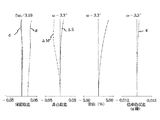
図1は本発明の数値実施例1のレンズ断面図、図2〜図4は本発明の数値実施例1の広角端,中間,望遠端の収差図である。図5は本発明の数値実施例2のレンズ断面図、図6〜図8は本発明の数値実施例2の広角端,中間,望遠端の収差図である。図9は本発明の数値実施例3のレンズ断面図、図10〜図12は本発明の数値実施例3の広角端,中間,望遠端の収差図である。
【0037】
レンズ断面図においてL1は正の屈折力の第1群、L2は負の屈折力の第2群、L3は正の屈折力の第3群、L4は正の屈折力の第4群、L5は負の屈折力の第5群、SPは絞り(開口絞り)であり第2群と第3群の間に設けている。絞りSPは変倍に伴って所定の条件で移動している。
【0038】
Gは赤外カットフィルター,ローパスフィルター等のフィルターであり、ガラスブロックとして示している。IPは像面である。
【0039】
本実施形態では広角端から望遠端への変倍に際して矢印のように第1群を物体側へ第2群を象面側へ移動させると共に、変倍に伴う象面変動を第4群を物体側に凸状の軌跡を有しつつ移動させて補正している
また、第4群を光軸上移動させてフォーカスを行うリアフォーカス式を採用している。同図に示す第4群の実線の曲線4aと点線の曲線4bは各々無限遠物体と近距離物体にフォーカスしているときの広角端から望遠端への変倍に伴う際の像面変動を補正する為の移動軌跡を示している。なお、第3群と第5群は変倍及びフォーカスの際固定である。
【0040】
本実施形態において、例えば望遠端において無限遠物体から近距離物体へフォーカスを行う場合は、同図の直線4cに示すように第4群を前方へ繰り出すことにより行っている。
【0041】
また、広角端から望遠端への変倍に際して絞りSPを所定の条件下で移動させている。
【0042】
次に具体的に各数値実施例のズームレンズのレンズ構成を説明する。
【0043】
図1の数値実施例1は、物体側から順に正の屈折力の第1群、負の屈折力の第2群、開口絞り、常時固定の正の屈折力の第3群、正の屈折力の第4群、そして常時固定の負の屈折力の第5群の5つのレンズ群を有し、広角端から望遠端への変倍に際して矢印のように該第1群を物体側に、該第2群を像面側へ移動させると同時に該開口絞りも像面側に移動させ、変倍に伴う像面変動を該第4群を移動させて補正している。また、第4群を光軸上移動させてフォーカスを行うリアフォーカス式を採用している。
【0044】
図5の数値実施例2は物体側から順に正の屈折力の第1群、負の屈折力の第2群、開口絞り、常時固定の正の屈折力の第3群、正の屈折力の第4群、そして常時固定の負の屈折力の第5群の5つのレンズ群を有し、広角端から望遠端への変倍に際して矢印のように該第1群を物体側に、該第2群を像面側へ移動させると共に変倍に伴う像面変動を該第4群を移動させて補正している。そして該開口絞りは、変倍に際して広角端から中間焦点距離まではほぼ不動の状態で、中間焦点距離から望遠端にかけては像面側に移動させている。また、第4群を光軸上移動させてフォーカスを行うリアフォーカス式を採用している。
【0045】
図9の数値実施例3は物体側から順に正の屈折力の第1群、負の屈折力の第2群、開口絞り、常時固定の正の屈折力の第3群、正の屈折力の第4群、そして常時固定の負の屈折力の第5群の5つのレンズ群を有し、広角端から望遠端への変倍に際して矢印のように該第1群を物体側に、該第2群を像面側へ移動させると共に変倍に伴う像面変動を該第4群を移動させて補正している。そして該開口絞りは、変倍に際して広角端から中間焦点距離までは物体側に移動させ、中間焦点距離から望遠端にかけては像面側に移動させている。また、第4群を光軸上移動させてフォーカスを行うリアフォーカス式を採用している。
【0046】
また、いずれの実施例においても、ズーミング中固定の第3群を光軸方向に略垂直に移動させて、被写体像の像面移動を補正することも可能である。
【0047】
本発明のズームレンズでは、このように変倍の際に第1,第2,第4のレンズ群そして絞りを移動させることにより複数のレンズ群に変倍をバランス良く分担させ,レンズ系全体の小型化を図りつつ効率よく変倍を行うと共に,全ズーム領域での収差補正を良好に行っている。
【0048】
本発明の目的とするズームレンズは以上の構成により達成されるが、更に本発明において広角端から望遠端に至り、また、物体距離全般にわたり良好なる光学性能を有し、小型のズームレンズを得るには次の諸条件のうちの少なくとも1つを満足させるのが良い。
【0049】
(ア−1)前記第1群は物体側に移動して広角端から望遠端への変倍を行なうことを特徴とすることである。これにより該第1群にも増倍作用を持たせてズーム比の高倍化を図っている。
【0050】
(アー2)変倍に伴う像面変動を該第4群を移動させて補正すると共に該第4群を移動させてフォーカスを行なうことを特徴とすることである。つまりリアフォーカス方式を採用することである。第1群を移動させてフォーカスを行うズームレンズに比べて第1群の有効径が小さくなり、レンズ系全体の小型化が容易になる。また、近接撮影、特に超至近撮影が容易となる。更に比較的軽量のレンズ群を移動させて行うため、レンズ群の駆動力が小さくてすみ迅速な焦点合わせを行うことができる等の特長がある。
【0051】
(ア−3)該第4群は、変倍に際して物体側に凸状の軌跡で移動することを特徴とすることである。これによれば(ア−2)と同様の効果が得られる。
【0052】
(ア−4)前記開口絞りは、広角端から望遠端への変倍の際、像面側に移動することを特徴とすることである。
【0053】
(ア−5)前記開口絞りは、広角端から望遠端への変倍の際、変倍範囲の中間位置から望遠端にかけて像面側に移動することを特徴とすることである。
【0054】
(ア−6)前記開口絞りは、広角端から望遠端への変倍の際、変倍範囲の中間位置でもっとも物体側に位置するような軌跡で移動することを特徴とすることである。前記構成のズームレンズの重量の大部分を決めているのは、第1群であり全体の約90%を占めている。これをいかに小さくするかがレンズの軽量小型化に大きく寄与してくる。
【0055】
該ズームレンズにおいて、第1群の有効径を決定しているのは変倍の中間位置における周辺の光線束である。これをレンズ光軸に近づけることにより第1群を小型化することが可能となる。すなわち開口絞りを可能な限り第1群に近づけることである。ただし近づけすぎると逆に像面近傍のレンズ系が大きくなったり、光学性能が劣化してしまうことがある。
【0056】
構成(p−4),(p−5),(p−6)は以上の理由により第1群の有効径を小さくしつつ,画面周辺で十分な光量を得るためのものである。
【0057】
(ア−7)前記第3群に対して前記開口絞りが光軸上最も離れる変倍位置と望遠端における第2群と該開口絞りの間隔を各々L2s、L2t、該変倍位置と望遠端における該開口絞りと第3群の間隔を各々Ls3、L3tとするとき、
0.4<(L2s−L2t)/(Ls3−L3t)<1.3 ・・・(1)
を満足する該開口絞りの位置が存在することを特徴とすることである。
【0058】
条件式(1)の上限値を超えて開口絞りを第3群側に近づけると,第1群と開口絞りの距離が大きくなり,第1群の有効径の小型化を図るのが困難になってくる。逆に、下限値を越えて第2群に近づきすぎると、像面近傍のレンズ群の有効径が大きくなり、光学性能を良好に保つことが困難になってくるので好ましくない。
【0059】
(ア−8)広角端と望遠端における全系の焦点距離をfw、ft、第2群の焦点距離をf2とおいたとき、
【0060】
【数7】
![]()
とする。
【0062】
0.19<|f2/fA|≦0.25 ・・・(2)
なる条件式を満足することを特徴とすることである。これは第2群の焦点距離を適正にするための条件である。条件式(2)の上限値を超えて第2群の焦点距離が長くなると、収差上は好ましいが所望のズーム比を得るためには該第2群の移動量を大きくしなくてはならず、レンズ系全体の大型化を招き好ましくない。逆に下限値を越えるとペッツバール和が負の方向に大きくなり、像面が倒れてくるので良好な光学性能を保つのが困難になる。
【0063】
(ア−9)広角端で無限遠物体の合焦状態において最終レンズ面から像面までの距離を空気に換算し、物体側の第1レンズ面から近軸像面までの距離(最も物体側のレンズ面と像面の間隔)をL、広角端と望遠端における全系の焦点距離をfw、ft、
【0064】
【数8】
![]()
とおいたとき
2.22<L/fA<3.36 ・・・(3)
なる条件式を満足することを特徴とすることである。条件式(3)の上限値を超えるとレンズ全長が長くなり好ましくない。逆に下限値を越えるとペッツバール和が負に大きくなり、像面が倒れてくるので良好な光学性能を保つのが困難になる。
【0066】
(ア−10)広角端から望遠端への変倍における前記第1群と第2群の移動量をS1、S2とおいたとき、
0.6<S1/S2<1.2 ・・・(4)
なる条件式を満足することを特徴とすることである。条件式(4)は広角端から望遠端への変倍の際の第1群と第2群の移動量の比に関し、主に変倍の際の収差変動を良好に補正しつつ第1群の有効径の小型化及びレンズ全長の短縮化の両方をバランス良く行うための条件である。上限値を越えて第1郡の移動量が増加すると、中間焦点距離から望遠端において該開口絞りからの距離が遠くなり、軸外光束がレンズ光軸から離れて第1群の有効径が大きくなってくるので好ましくない。逆に下限値を越えて第1群の移動量が少なくなると広角端でのレンズ全長を短くすることが難しくなったり、所望の変倍比を売るのが困難となってくる。
【0067】
(ア−11)前記第5群は、変倍に際し常時固定であることを特徴とすることである。
【0068】
(ア−12)前記第3群を光軸方向にほぼ垂直に移動させて、前記ズームレンズが振動したときの被写体象の像面位置を補正することを特徴とすることである。
【0069】
(ア−13)該第2群は物体側より順に像面側に強い凹面を向けた負の21レンズ、両レンズ面が凹面の負の第22レンズ、そして像側に比べ物体側に強い凸面を向けた正レンズと負レンズとを接合した正の第23接合レンズを有することが望ましい。
【0070】
本発明のようなズームタイプで変倍比を上げる場合、変倍機能に大きく寄与する第2群の移動量を大きくするか、該第2群の焦点距離を短くする必要がある。
【0071】
前記の方法は、ズームレンズの大型化を招き好ましくなく、後記の方法はレンズは大きくならないものの第2群に負担が大きくかかり、光学性能を良好に保つ事が困難になってくる。そこで上述の如く第2群を構成することにより光学性能を良好に補正することができる。
【0072】
(ア−14)第2群は少なくとも1つの非球面を有することである。非球面を配置することにより軸外の光学性能を向上することができる。また、第2群の屈折力を強くすることも可能になり、結果的に第2群の移動量を少なくすることができ、レンズ全長を短くすることができる。また、該第2群中の非球面は、曲率半径の小さい、負の第21レンズの像面側の面、または負の第22レンズの物体側の面、または正の第23レンズの物体側の面に配置することにより、より効果的に収差を補正することが可能になる。特に軸外のフレアーを良好に補正できる。なお、非球面は、レンズの周辺部にいくにしたがって屈折力が弱くなる形状となることが望ましい。
【0073】
(ア−15)該第2群の正レンズの材質の平均アッベ数をνp、負レンズの材質の平均アッベ数をνnとおいたとき
20<νp<35 ・・・(5)
36<νn<65 ・・・(6)
なる条件式を少なくとも1つ満足することが望ましい。これは第2群で発生する色収差を良好に補正している。該第2群は変倍に大きく寄与しているのでここで発生する収差は良好に補正しておかなければならない。特に変倍比が10倍程度の高変倍比のズームレンズにおいては色収差も良好に補正することが重要である。
【0074】
条件式(5)の上限値を超えると軸上色収差がオーバーになり補正過剰となる。逆に、下限値を超えると軸上色収差がアンダーになり補正不足となる。条件式(6)は条件式(5)の場合と現象の発生は逆になるが、上限値あるいは下限値を超えるとやはり色収差を良好に補正することが難しい。
【0075】
(ア−16)前記第2群の負レンズの材質の平均屈折力をNnとおいたとき、
1.80<Nn<1.96 ・・・(7)
なる条件式を満足することである。これは条件式(2)とも関係してくるが、負レンズに高屈折率ガラスを用いてペッツバール和の悪化を防ぐ為の条件で、限界値を超えると像面湾曲が悪化してくる。
(ア−17)該第2群のレンズの曲率半径を物体側から順にR2iとおいたとき
0.60<|R22/R23|<0.82 ・・・(8)
なる条件式を満足することである。これらはコマ収差と像面湾曲そしてフレアーをバランス良く補正する条件である。条件式(8)の上限値を超えるとコマ収差が大きくなってくる。逆に下限値を超えると像面が物体側に凹となるように湾曲し好ましくない。更に、上限値または下限値を超えると共にフレアーが大きくなり好ましくない。
【0076】
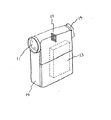
次に本発明のズームレンズを用いたビデオカメラ(光学機器)の実施形態を図13を用いて説明する。
【0077】
図13において、10はビデオカメラ本体、11は本発明のズームレンズによって構成された撮影光学系、12は撮影光学系11によって被写体像を受光するCCD等の撮像素子、13は撮像素子12が受光した被写体像を記録する記録手段、14は不図示の表示素子に表示された被写体像を観察するためのファインダーである。上記表示素子は液晶パネル等によって構成され、撮像素子12上に形成された被写体像が表示される。
【0078】
このように本発明のズームレンズをビデオカメラやデジタルスチルカメラ等の電子カメラに適用することにより、小型で高い光学性能を有する光学機器を実現している。
【0079】
以下に、本発明の各数値実施例を記載する。
【0080】
数値実施例において、Riは物体側より順に第i番目の面の曲率半径、Diは物体側より順に第i番目のレンズ厚及び空気間隔、Niとνiはそれぞれ物体側より順に第i番目の光学部材の材質の屈折率とアッベ数である。
【0081】
非球面形状は、光軸方向にX軸、光軸と垂直方向H軸、光の進行方向を正とし、Rを近軸曲率半径、各非球面係数をK,B,C,D,E,Fとしたとき、
【0082】
【数9】

なる式で表している。
【0084】
また、例えば「e−Z」の表示は「10-Z」を意味する。前述の各条件式と数値実施例における諸数値との関係を表−1に示す。
【0085】
【外1】
【外2】
【外3】
【表1】
【発明の効果】
本発明によれば、変倍に伴う所定のレンズ群の移動条件や各レンズ群の屈折力、そしてレンズ構成等を適切に設定することにより、レンズ構成の簡素化を図りつつ、全変倍範囲にわたり、また、高い光学性能を有するレンズ全長の短い小型ズームレンズ及びそれを用いた光学機器を達成することができる。
【0090】
この他本発明によれば、以上説明したように構成することにより、ズーム比が10倍と高変倍比にもかかわらずレンズ系全体を小型化し、さらにFナンバーが1.6程度と大口径比でありながら、高い光学性能を有しレンズの構成枚数が少ないズームレンズを実現することができる。
【図面の簡単な説明】
【図1】 本発明の数値実施例1のレンズ断面図
【図2】 本発明の数値実施例1の広角端における収差図
【図3】 本発明の数値実施例1の中間における収差図
【図4】 本発明の数値実施例1の望遠端における収差図
【図5】 本発明の数値実施例2のレンズ断面図
【図6】 本発明の数値実施例2の広角端における収差図
【図7】 本発明の数値実施例2の中間における収差図
【図8】 本発明の数値実施例2の望遠端における収差図
【図9】 本発明の数値実施例3のレンズ断面図
【図10】 本発明の数値実施例3の広角端における収差図
【図11】 本発明の数値実施例3の中間における収差図
【図12】 本発明の数値実施例3の望遠端における収差図
【図13】 本発明の光学機器の要部概略図
【符号の説明】
L1 第1群
L2 第2群
L3 第3群
L4 第4群
L5 第5群
d d線
g g線
ΔM メリディオナル像面
ΔS サジタル像面
10 ビデオカメラ本体
11 ズームレンズ
12 撮像素子
13 記録手段
14 ファインダー[0001]
BACKGROUND OF THE INVENTION
The present invention relates to a zoom lens and an optical apparatus using the same, and is particularly suitable for an electronic camera such as a video camera or a digital still camera. In addition, the present invention relates to a zoom lens having a zoom ratio of 10 times and a high zoom ratio, and an F number at the wide-angle end of about 1.6, a large aperture ratio and a short overall length, and an optical apparatus using the same. .
[0002]
[Prior art]
Conventionally, zoom lenses having a small lens system and a relatively high zoom ratio have been proposed in, for example, Japanese Patent Laid-Open Nos. 56-114920 and 58-160913. These are composed of a first group of positive refractive power, a second group of negative refractive power, a third group of positive refractive power, and a fourth group of positive refractive power in order from the object side. The first group, the second group, and the fourth group are moved, so that a relatively high zoom ratio is obtained while the entire lens system is small.
[0003]
On the other hand, in Japanese Patent Laid-Open Nos. 62-24213 and 63-247316, a first group having a positive refractive power, a second group having a negative refractive power, and a third having a positive refractive power in order from the object side. A fourth lens group having a positive refractive power, and moving the second group to perform zooming, and correcting the image plane variation accompanying zooming by moving the fourth group and correcting the first lens group. Focusing is done in 4 groups.
[0004]
In JP-A-4-14007, in order from the object side, a first group having a positive refractive power, a second group having a negative refractive power, a stop, a third group having a positive refractive power, and a positive refractive power. Consists of a fourth group, the first group is moved to the object side for zooming from the wide-angle end to the telephoto end, the second group is moved to the image side, the fourth group is moved for zooming and focusing, and the aperture is further opened A zoom lens is disclosed in which the stop is moved to the image plane side by zooming from the intermediate focal length to the telephoto end.
[0005]
In JP-A-58-129404 and JP-A-61-258217, in order from the object side, a first group having a positive refractive power, a second group having a negative refractive power, a third group having a positive refractive power, In a zoom lens composed of five lens units of a fourth group having a refractive power of 5 and a fifth group having a negative refractive power, focusing is performed by moving the fifth group or a plurality of lens groups including the fifth group. ing.
[0006]
In Japanese Patent Laid-Open No. 4-301811, in order from the object side, a first group having a positive refractive power, a second group having a negative refractive power, a third group having a positive refractive power, and a fourth group having a positive refractive power. Then, it has five lens groups of negative fifth refractive power, and the first group is moved to the object side and the second group is moved to the image plane side to perform zooming from the wide angle end to the telephoto end. The image plane variation due to zooming is corrected by moving the fourth group, and the fourth group is moved for focusing.
[0007]
In US Reissued Patent Specification No. 32923, a first positive lens group, a second negative lens group, a stop, and a third positive lens group and a fourth positive lens group are arranged in order from the object side. A zoom lens is disclosed in which the four lens groups move in the same direction during zooming, and the diaphragm is fixed during zooming.
[0008]
[Problems to be solved by the invention]
In general, in a zoom lens, in order to have a high zoom ratio while reducing the size of the entire lens system and to obtain high optical performance in the entire zoom range, the lens configuration, the refractive power of each group, etc. are set appropriately. There is a need to.
[0009]
For example, the movement conditions of each lens group accompanying zooming, the refractive power of each lens group, the lens configuration of the lens group that performs zooming, the selection of the lens group for focusing, the lens configuration, and the optical action of the aperture stop If these are not set appropriately, the occurrence of various aberrations increases during zooming and focusing, and it becomes difficult to obtain an image with good image quality while achieving high zooming.
[0010]
In the present invention, by appropriately setting the movement conditions of the predetermined lens units accompanying the zooming, the refractive power of each lens unit, and the lens configuration, etc., the lens configuration can be simplified and the entire zooming range can be achieved. Another object of the present invention is to provide a small zoom lens having high optical performance and a short overall lens length, and an optical apparatus using the same.
[0011]
Another object of the present invention is to reduce the size of the entire lens system in spite of a high zoom ratio of 10 times. Another object of the present invention is to provide a zoom lens having high optical performance and a small number of lenses, while having a large aperture ratio of F number of about 1.6.
[0012]
[Means for Solving the Problems]
The zoom lens according to the first aspect of the present invention includes, in order from the object side to the image side, a first group having a positive refractive power, a second group having a negative refractive power, an aperture stop, a third group having a positive refractive power, and a positive group. The zoom lens is composed of a fourth group having a refractive power and a fifth group having a negative refractive power. Upon zooming from the wide angle end to the telephoto end, the first group moves toward the object side, and the second group moves toward the image plane side. The aperture stop moves, the third group is fixed, the fourth group moves with a convex locus toward the object side, the fifth group is fixed, and the fourth group moves. The focal length of the entire system at the wide-angle end and the telephoto end is fw, ft, the focal length of the second group is f2, and the average refractive index of the negative lens constituting the second group is Nn. and when,
0.19 <| f2 / √ (fw · ft) | ≦ 0.25
1.80 <Nn <1.96
It satisfies the following conditional expression.
[0013]
According to a second aspect of the present invention, in the first aspect of the present invention, the aperture stop moves to the image plane side upon zooming from the wide-angle end to the telephoto end.
[0014]
According to a third aspect of the present invention, in the first aspect of the invention, the aperture stop moves toward the image plane from the middle position of the zoom range to the telephoto end when zooming from the wide-angle end to the telephoto end. .
[0015]
According to a fourth aspect of the present invention, in the first aspect of the invention, the aperture stop moves so as to be located closest to the object side in the middle position of the zooming range when zooming from the wide-angle end to the telephoto end. Yes.
[0016]
According to a fifth aspect of the present invention, there is provided the zoom lens according to any one of the first to fourth aspects, wherein the aperture stop is farthest on the optical axis relative to the third group, and the second group and the aperture at the telephoto end. When the distance between the aperture stops is L2s and L2t, and the distance between the aperture stop and the third group at the telephoto end where the aperture stop is farthest on the optical axis with respect to the third group is Ls3 and L3t, respectively. ,
0.4 <(L2s-L2t) / (Ls3-L3t) <1.3
It is characterized by satisfying.
[0017]
According to a sixth aspect of the present invention, in the invention according to any one of the first to fifth aspects, the distance between the lens surface closest to the object side and the image plane at the wide-angle end of the zoom lens is L, and the entire system at the wide-angle end and the telephoto end is When the focal lengths are fw and ft, respectively.
2.22 <L / √ (fw · ft) <3.36
It satisfies the following conditional expression.
[0018]
The invention of claim 7 is the invention of any one of claims 1 to 6, wherein the movement amounts of the first group and the second group in zooming from the wide-angle end to the telephoto end are S1 and S2, respectively. ,
0.6 <S1 / S2 <1.2
It satisfies the following conditional expression.
[0019]
According to an eighth aspect of the present invention, in the invention according to any one of the first to seventh aspects, the imaging position is changed when the third lens group is moved in the direction perpendicular to the optical axis and the zoom lens vibrates. It is characterized by correcting.
[0020]
The invention of claim 9 is the invention according to any one of claims 1 to 8, wherein the second group includes a meniscus negative lens having a convex surface facing the object side, a negative lens having concave both lens surfaces, and both lenses. It consists of a cemented lens in which a positive lens having a convex surface and a negative lens are cemented together, and the average Abbe number of the positive lens constituting the second group is νp, and the average Abbe number of the negative lens constituting the second group When the value is νn,
20 <νp <35
36 <νn <65
It is characterized by satisfying.
[0021]
The invention of claim 10 is the invention of any one of claims 1 to 9, wherein the radius of curvature of the i-th lens surface from the object side of the second group is R2i.
0.6 <| R22 / R23 | <0.82
It is characterized by satisfying.
[0022]
An optical apparatus according to an eleventh aspect of the present invention includes the zoom lens according to any one of the first to tenth aspects.
[0036]
DETAILED DESCRIPTION OF THE INVENTION
FIG. 1 is a lens cross-sectional view of Numerical Example 1 of the present invention, and FIGS. 2 to 4 are aberration diagrams at the wide-angle end, middle, and telephoto end of Numerical Example 1 of the present invention. FIG. 5 is a lens cross-sectional view of Numerical Example 2 of the present invention, and FIGS. 6 to 8 are aberration diagrams at the wide-angle end, middle, and telephoto end of Numerical Example 2 of the present invention. FIG. 9 is a lens cross-sectional view of Numerical Example 3 of the present invention, and FIGS. 10 to 12 are aberration diagrams at the wide-angle end, middle, and telephoto end of Numerical Example 3 of the present invention.
[0037]
In the lens sectional view, L1 is a first group having positive refractive power, L2 is a second group having negative refractive power, L3 is a third group having positive refractive power, L4 is a fourth group having positive refractive power, and L5 is The fifth group, SP, having a negative refractive power, is a stop (aperture stop), and is provided between the second group and the third group. The aperture stop SP is moved under a predetermined condition with zooming.
[0038]
G is a filter such as an infrared cut filter or a low-pass filter, and is shown as a glass block. IP is the image plane.
[0039]
In this embodiment, when zooming from the wide-angle end to the telephoto end, the first group is moved to the object side as indicated by the arrow, and the second group is moved to the elephant side. It is corrected by moving it while having a convex locus on the side, and a rear focus method is adopted in which focusing is performed by moving the fourth lens unit on the optical axis. The
[0040]
In the present embodiment, for example, when focusing from an infinitely distant object to a close object at the telephoto end, the fourth group is moved forward as indicated by a
[0041]
Further, the aperture stop SP is moved under a predetermined condition at the time of zooming from the wide angle end to the telephoto end.
[0042]
Next, the lens configuration of the zoom lens of each numerical example will be specifically described.
[0043]
Numerical example 1 of FIG. 1 is the first group having positive refractive power, the second group having negative refractive power, the aperture stop, the third group having always positive positive power, and the positive refractive power in order from the object side. And a fifth lens group having a negative refractive power that is always fixed, and the first group is moved to the object side as indicated by an arrow when zooming from the wide-angle end to the telephoto end. At the same time when the second group is moved to the image plane side, the aperture stop is also moved to the image plane side, and the image plane variation accompanying zooming is corrected by moving the fourth group. In addition, a rear focus type is employed in which focusing is performed by moving the fourth group on the optical axis.
[0044]
Numerical Example 2 in FIG. 5 shows the first group of positive refractive power, the second group of negative refractive power, the aperture stop, the third group of positive refractive power that is always fixed, and the positive refractive power in order from the object side. There are five lens groups, a fourth group and a fifth lens group having a negative refractive power that is always fixed, and the first group is placed on the object side as indicated by an arrow when zooming from the wide-angle end to the telephoto end. The second group is moved to the image plane side, and the image plane variation accompanying zooming is corrected by moving the fourth group. The aperture stop is substantially stationary from the wide angle end to the intermediate focal length during zooming, and is moved to the image plane side from the intermediate focal length to the telephoto end. In addition, a rear focus type is employed in which focusing is performed by moving the fourth group on the optical axis.
[0045]
In numerical example 3 of FIG. 9, in order from the object side, the first group of positive refractive power, the second group of negative refractive power, the aperture stop, the third group of always positive positive refractive power, the positive refractive power There are five lens groups, a fourth group and a fifth lens group having a negative refractive power that is always fixed, and the first group is placed on the object side as indicated by an arrow when zooming from the wide-angle end to the telephoto end. The second group is moved to the image plane side, and the image plane variation accompanying zooming is corrected by moving the fourth group. The aperture stop is moved to the object side from the wide-angle end to the intermediate focal length during zooming, and is moved to the image plane side from the intermediate focal length to the telephoto end. In addition, a rear focus type is employed in which focusing is performed by moving the fourth group on the optical axis.
[0046]
In any of the embodiments, it is also possible to correct the image plane movement of the subject image by moving the third group fixed during zooming substantially perpendicularly to the optical axis direction.
[0047]
In the zoom lens according to the present invention, the first, second, and fourth lens groups and the diaphragm are moved during zooming so that the zooming is distributed among the plurality of lens groups in a well-balanced manner. While zooming in efficiently while miniaturizing, aberration correction is well performed in the entire zoom range.
[0048]
The zoom lens that is the object of the present invention is achieved by the above configuration. In the present invention, the zoom lens extends from the wide-angle end to the telephoto end, and has a good optical performance over the entire object distance, thereby obtaining a small zoom lens. It is preferable to satisfy at least one of the following conditions.
[0049]
(A-1) The first group is characterized in that it moves toward the object side and performs zooming from the wide-angle end to the telephoto end. As a result, the first lens group also has a multiplying action to increase the zoom ratio.
[0050]
(Ar 2) The present invention is characterized in that the image plane variation caused by zooming is corrected by moving the fourth group, and focusing is performed by moving the fourth group. That is, the rear focus method is adopted. The effective diameter of the first lens unit is smaller than that of a zoom lens that moves the first lens unit to focus, and the entire lens system can be easily downsized. In addition, close-up photography, particularly ultra close-up photography is facilitated. Further, since the relatively light lens group is moved, the driving force of the lens group is small, so that quick focusing can be performed.
[0051]
(A-3) The fourth group is characterized by moving along a convex locus toward the object side upon zooming. According to this, the same effect as (A-2) can be obtained.
[0052]
(A-4) The aperture stop moves to the image plane side upon zooming from the wide-angle end to the telephoto end.
[0053]
(A-5) The aperture stop moves to the image plane side from the intermediate position of the zooming range to the telephoto end when zooming from the wide-angle end to the telephoto end.
[0054]
(A-6) The aperture stop moves along a trajectory that is located closest to the object side in the middle position of the zooming range when zooming from the wide-angle end to the telephoto end. It is the first group that determines most of the weight of the zoom lens configured as described above, which occupies about 90% of the total. How to reduce this greatly contributes to the reduction in weight and size of the lens.
[0055]
In the zoom lens, the effective diameter of the first lens unit is determined by the peripheral light flux at the intermediate position of zooming. By bringing this closer to the lens optical axis, the first group can be reduced in size. That is, to bring the aperture stop as close to the first group as possible. However, if it is too close, the lens system in the vicinity of the image plane may become large or the optical performance may deteriorate.
[0056]
The configurations (p-4), (p-5), and (p-6) are for obtaining a sufficient amount of light around the screen while reducing the effective diameter of the first group for the above reasons.
[0057]
(A-7) The distance between the second lens unit and the aperture stop at the zoom position at which the aperture stop is farthest on the optical axis with respect to the third lens unit and the aperture stop at L2s and L2t, respectively, and the zoom position and the telephoto end When the distance between the aperture stop and the third lens unit is Ls3 and L3t, respectively,
0.4 <(L2s-L2t) / (Ls3-L3t) <1.3 (1)
There exists a position of the aperture stop that satisfies the following.
[0058]
If the upper limit value of conditional expression (1) is exceeded and the aperture stop is brought closer to the third group side, the distance between the first group and the aperture stop will increase, making it difficult to reduce the effective diameter of the first group. Come. On the other hand, if the value exceeds the lower limit and is too close to the second group, the effective diameter of the lens group in the vicinity of the image surface becomes large, and it becomes difficult to maintain good optical performance.
[0059]
(A-8) When the focal length of the entire system at the wide-angle end and the telephoto end is fw, ft, and the focal length of the second group is f2,
[0060]
[Expression 7]
![]()
And
[0062]
0.19 <| f2 / fA | ≦ 0.25 (2)
The following conditional expression is satisfied. This is a condition for making the focal length of the second group appropriate. When the focal length of the second group becomes longer than the upper limit value of conditional expression (2), it is preferable in terms of aberration, but in order to obtain a desired zoom ratio, the movement amount of the second group must be increased. This is not preferable because it increases the size of the entire lens system. On the other hand, if the lower limit is exceeded, the Petzval sum increases in the negative direction and the image plane falls, making it difficult to maintain good optical performance.
[0063]
(A-9) The distance from the last lens surface to the image plane is converted to air in the in- focus state of an object at infinity at the wide angle end, and the distance from the first lens surface on the object side to the paraxial image plane (most object side) L ) between the lens surface and the image plane) , and the focal lengths of the entire system at the wide-angle end and the telephoto end are fw, ft,
[0064]
[Equation 8]
![]()
2.22 <L / fA <3.36 (3)
The following conditional expression is satisfied. Exceeding the upper limit of conditional expression (3) is not preferable because the total lens length becomes long. On the other hand, if the lower limit is exceeded, the Petzval sum will become negative and the image plane will fall, making it difficult to maintain good optical performance.
[0066]
(A-10) When the movement amounts of the first group and the second group in zooming from the wide-angle end to the telephoto end are set as S1 and S2,
0.6 <S1 / S2 <1.2 (4)
The following conditional expression is satisfied. Conditional expression (4) relates to the ratio of the amount of movement between the first group and the second group at the time of zooming from the wide-angle end to the telephoto end, and mainly corrects aberration fluctuations at the time of zooming while favorably correcting the first group. This is a condition for achieving both a reduction in the effective diameter of the lens and a reduction in the total lens length in a balanced manner. When the movement amount of the first group increases beyond the upper limit value, the distance from the aperture stop is increased from the intermediate focal length to the telephoto end, the off-axis light beam is separated from the lens optical axis, and the effective diameter of the first group is increased. This is not preferable. On the other hand, if the amount of movement of the first lens unit decreases beyond the lower limit, it becomes difficult to shorten the total lens length at the wide-angle end, and it becomes difficult to sell a desired zoom ratio.
[0067]
(A-11) The fifth group is characterized in that it is always fixed during zooming.
[0068]
(A-12) The third group is moved substantially perpendicularly to the optical axis direction to correct the image plane position of the subject image when the zoom lens vibrates .
[0069]
(A-13) The second lens group has a negative 21 lens with a strong concave surface facing the image surface side in order from the object side, a negative 22nd lens whose both lens surfaces are concave surfaces, and a strong convex surface on the object side compared to the image side. It is desirable to have a positive twenty-third cemented lens in which the positive lens and the negative lens directed are cemented.
[0070]
When the zoom ratio is increased in the zoom type as in the present invention, it is necessary to increase the movement amount of the second group that greatly contributes to the zooming function or shorten the focal length of the second group.
[0071]
The method described above is not preferable because it leads to an increase in the size of the zoom lens, and the method described below is burdensome on the second group, although the lens does not become large, and it becomes difficult to maintain good optical performance. Therefore, by configuring the second group as described above, the optical performance can be favorably corrected.
[0072]
(A-14) The second group has at least one aspherical surface. By arranging an aspherical surface, off-axis optical performance can be improved. In addition, the refractive power of the second group can be increased, and as a result, the amount of movement of the second group can be reduced, and the overall lens length can be shortened. The aspherical surface in the second group has a small curvature radius, the image side surface of the negative 21st lens, the object side surface of the negative 22nd lens, or the object side of the positive 23rd lens. By disposing the lens on the surface, aberration can be corrected more effectively. The off-axis of the flare can be satisfactorily corrected, especially. It is desirable that the aspherical surface has a shape in which the refractive power becomes weaker toward the periphery of the lens.
[0073]
(A-15) 20 <νp <35 (5) where the average Abbe number of the material of the positive lens in the second group is νp and the average Abbe number of the material of the negative lens is νn.
36 <νn <65 (6)
It is desirable to satisfy at least one of the following conditional expressions. This corrects the chromatic aberration generated in the second group well. Since the second group greatly contributes to zooming, the aberration generated here must be corrected well. In particular, in a zoom lens having a high zoom ratio of about 10 times, it is important to correct chromatic aberration well.
[0074]
If the upper limit of conditional expression (5) is exceeded, the axial chromatic aberration will be over and overcorrected. On the contrary, if the lower limit is exceeded, the axial chromatic aberration will be under and correction will be insufficient. Conditional expression (6) reverses the occurrence of the phenomenon as in conditional expression (5), but if the upper limit value or lower limit value is exceeded, it is difficult to correct chromatic aberration well.
[0075]
(A-16) When the average refractive power of the material of the negative lens of the second group is Nn,
1.80 <Nn <1.96 (7)
The following conditional expression is satisfied. This is also related to conditional expression (2), but it is a condition for preventing the Petzval sum from deteriorating by using a high refractive index glass for the negative lens. When the limit value is exceeded, curvature of field deteriorates.
(A-17) 0.62 <| R22 / R23 | <0.82 (8) when the radius of curvature of the second lens group is set to R2i in order from the object side.
The following conditional expression is satisfied. These are conditions for correcting coma aberration, field curvature and flare in a well-balanced manner. When the upper limit value of conditional expression (8) is exceeded, coma aberration increases. On the contrary, when the lower limit is exceeded, the image surface is curved so as to be concave toward the object side, which is not preferable. Further, the upper limit value or the lower limit value is exceeded, and the flare becomes unfavorable.
[0076]
Next, an embodiment of a video camera (optical apparatus) using the zoom lens of the present invention will be described with reference to FIG.
[0077]
In FIG. 13, 10 is a video camera body, 11 is a photographic optical system constituted by the zoom lens of the present invention, 12 is an image sensor such as a CCD that receives a subject image by the photographic
[0078]
In this way, by applying the zoom lens of the present invention to an electronic camera such as a video camera or a digital still camera, a small optical device having high optical performance is realized.
[0079]
Hereinafter, each numerical example of the present invention will be described.
[0080]
In numerical examples, Ri is the radius of curvature of the i-th surface in order from the object side, Di is the i-th lens thickness and air spacing in order from the object side, and Ni and νi are the i-th optical in order from the object side. The refractive index and Abbe number of the material of the member.
[0081]
The aspherical shape has an X axis in the optical axis direction, an H axis perpendicular to the optical axis, a positive light traveling direction, R is a paraxial radius of curvature, and each aspheric coefficient is K, B, C, D, E, When F
[0082]
[Equation 9]
It is expressed by the following formula.
[0084]
For example, “e-Z” means “10 −Z ”. Table 1 shows the relationship between the above-described conditional expressions and various numerical values in the numerical examples.
[0085]
[Outside 1]
[Outside 2]
[Outside 3]
[Table 1]
【The invention's effect】
According to the present invention, it is possible to simplify the lens configuration by appropriately setting the movement condition of the predetermined lens unit accompanying the zooming, the refractive power of each lens unit, the lens configuration, and the like. In addition, a small zoom lens having a high overall optical performance and a short overall lens length and an optical apparatus using the same can be achieved.
[0090]
In addition to this, according to the present invention, the lens system as a whole is miniaturized in spite of the zoom ratio of 10 times and the high zoom ratio, and the F-number is about 1.6. Although the ratio is high, a zoom lens having high optical performance and a small number of lenses can be realized.
[Brief description of the drawings]
1 is a lens cross-sectional view of Numerical Example 1 of the present invention. FIG. 2 is an aberration diagram at the wide-angle end of Numerical Example 1 of the present invention. FIG. 3 is an aberration diagram in the middle of Numerical Example 1 of the present invention. FIG. 5 is an aberration diagram at the telephoto end of Numerical Example 1 of the present invention. FIG. 5 is a lens cross-sectional view of Numerical Example 2 of the present invention. FIG. 8 is an aberration diagram at the telephoto end of Numerical Example 2 of the present invention. FIG. 9 is a lens cross-sectional view of Numerical Example 3 of the present invention. FIG. 11 is an aberration diagram in the middle of Numerical Example 3 of the present invention. FIG. 12 is an aberration diagram at the telephoto end of Numerical Example 3 in the present invention. Schematic diagram of essential parts of the optical apparatus of the invention
L1 1st group L2 2nd group L3 3rd group L4 4th group L5 5th group d d line g g line ΔM meridional image plane ΔS sagittal image plane 10 video camera body 11
Claims (11)
0.19<|f2/√(fw・ft)|≦0.25
1.80<Nn<1.96
なる条件式を満足することを特徴とするズームレンズ。In order from the object side to the image side, a first group having a positive refractive power, a second group having a negative refractive power, an aperture stop, a third group having a positive refractive power, a fourth group having a positive refractive power, and a negative refraction. The first group is moved to the object side, the second group is moved to the image plane side, and the aperture stop is moved during zooming from the wide-angle end to the telephoto end. The third group is fixed, the fourth group moves with a convex locus toward the object side, the fifth group is fixed, and the fourth group is moved to perform focusing, and the wide-angle end and the telephoto end When the focal length of the entire system at the end is fw, ft, the focal length of the second group is f2, and the average value of the refractive index of the negative lens constituting the second group is Nn,
0.19 <| f2 / √ (fw · ft) | ≦ 0.25
1.80 <Nn <1.96
A zoom lens satisfying the following conditional expression:
0.4<(L2s−L2t)/(Ls3−L3t)<1.3
を満足することを特徴とする請求項1乃至4のいずれか1項に記載のズームレンズ。The distance between the second group and the aperture stop at the zoom position where the aperture stop is farthest on the optical axis with respect to the third group and the telephoto end are L2s and L2t, respectively, and the aperture stop is relative to the third group. When the distance between the aperture stop and the third group at the zoom position most distant from the optical axis and the telephoto end is Ls3 and L3t, respectively.
0.4 <(L2s-L2t) / (Ls3-L3t) <1.3
5. The zoom lens according to claim 1, wherein the zoom lens satisfies the following.
2.22<L/√(fw・ft)<3.36
なる条件式を満足することを特徴とする請求項1乃至5のいずれか1項記載のズームレンズ。When the distance between the lens surface closest to the object side and the image plane at the wide-angle end of the zoom lens is L, and the focal lengths of the entire system at the wide-angle end and the telephoto end are fw and ft, respectively.
2.22 <L / √ (fw · ft) <3.36
The zoom lens according to claim 1, wherein the following conditional expression is satisfied.
0.6<S1/S2<1.2
なる条件式を満足することを特徴とする請求項1から6のいずれか1項に記載のズームレンズ。When the movement amounts of the first group and the second group in zooming from the wide-angle end to the telephoto end are S1 and S2, respectively,
0.6 <S1 / S2 <1.2
The zoom lens according to claim 1, wherein the following conditional expression is satisfied.
20<νp<35
36<νn<65
を満足することを特徴とする請求項1から8のいずれか1項に記載のズームレンズ。The second group includes a meniscus negative lens having a convex surface directed toward the object side, a negative lens having concave surfaces on both lens surfaces, and a cemented lens in which a positive lens and a negative lens having convex surfaces are cemented to each other. When the average value of Abbe numbers of the positive lenses constituting the second group is νp and the average value of Abbe numbers of the negative lenses constituting the second group is νn,
20 <νp <35
36 <νn <65
The zoom lens according to claim 1, wherein the zoom lens satisfies the following.
0.6<|R22/R23|<0.82
を満足することを特徴とする請求項1から9のいずれか1項に記載のズームレンズ。When the radius of curvature of the i-th lens surface from the object side of the second group is R2i,
0.6 <| R22 / R23 | <0.82
The zoom lens according to claim 1, wherein the zoom lens satisfies the following.
Priority Applications (2)
| Application Number | Priority Date | Filing Date | Title |
|---|---|---|---|
| JP2000138906A JP4564625B2 (en) | 2000-05-11 | 2000-05-11 | Zoom lens and optical apparatus using the same |
| US09/851,195 US6587280B2 (en) | 2000-05-11 | 2001-05-09 | Zoom lens and optical device using the same |
Applications Claiming Priority (1)
| Application Number | Priority Date | Filing Date | Title |
|---|---|---|---|
| JP2000138906A JP4564625B2 (en) | 2000-05-11 | 2000-05-11 | Zoom lens and optical apparatus using the same |
Publications (3)
| Publication Number | Publication Date |
|---|---|
| JP2001318315A JP2001318315A (en) | 2001-11-16 |
| JP2001318315A5 JP2001318315A5 (en) | 2007-06-14 |
| JP4564625B2 true JP4564625B2 (en) | 2010-10-20 |
Family
ID=18646447
Family Applications (1)
| Application Number | Title | Priority Date | Filing Date |
|---|---|---|---|
| JP2000138906A Expired - Fee Related JP4564625B2 (en) | 2000-05-11 | 2000-05-11 | Zoom lens and optical apparatus using the same |
Country Status (1)
| Country | Link |
|---|---|
| JP (1) | JP4564625B2 (en) |
Families Citing this family (8)
| Publication number | Priority date | Publication date | Assignee | Title |
|---|---|---|---|---|
| JP4507064B2 (en) * | 2003-12-18 | 2010-07-21 | ソニー株式会社 | Zoom lens and imaging device |
| JP4888029B2 (en) * | 2006-10-11 | 2012-02-29 | 株式会社ニコン | Zoom lens, imaging device, zoom lens zooming method |
| JP5115834B2 (en) | 2007-03-05 | 2013-01-09 | 株式会社ニコン | Zoom lens, optical apparatus, and imaging method |
| JP5645520B2 (en) * | 2010-07-20 | 2014-12-24 | キヤノン株式会社 | Zoom lens and imaging apparatus having the same |
| JP5224479B2 (en) * | 2010-12-20 | 2013-07-03 | 富士フイルム株式会社 | Variable magnification optical system with image stabilization function and imaging apparatus equipped with the variable magnification optical system |
| CN104755985B (en) | 2012-10-30 | 2018-07-31 | 株式会社尼康 | Variable-power optical system and Optical devices |
| JP6131566B2 (en) * | 2012-10-30 | 2017-05-24 | 株式会社ニコン | Variable magnification optical system, optical device |
| CN113625420B (en) * | 2020-05-06 | 2022-10-04 | 华为技术有限公司 | Optical lens, lens module and terminal |
Citations (6)
| Publication number | Priority date | Publication date | Assignee | Title |
|---|---|---|---|---|
| JPS61259217A (en) * | 1985-05-14 | 1986-11-17 | Canon Inc | Magnification varying method for zoom lens |
| JPH03215810A (en) * | 1990-01-20 | 1991-09-20 | Canon Inc | Rear focus type zoom lens |
| JPH04294311A (en) * | 1991-03-23 | 1992-10-19 | Canon Inc | Zoom lens |
| JPH04301811A (en) * | 1991-03-29 | 1992-10-26 | Canon Inc | Zoom lens of rear focus system |
| JPH07199124A (en) * | 1993-12-28 | 1995-08-04 | Nikon Corp | Zoom lens with oscillation-proof function |
| JPH11109233A (en) * | 1997-09-30 | 1999-04-23 | Minolta Co Ltd | Zoom lens system |
-
2000
- 2000-05-11 JP JP2000138906A patent/JP4564625B2/en not_active Expired - Fee Related
Patent Citations (6)
| Publication number | Priority date | Publication date | Assignee | Title |
|---|---|---|---|---|
| JPS61259217A (en) * | 1985-05-14 | 1986-11-17 | Canon Inc | Magnification varying method for zoom lens |
| JPH03215810A (en) * | 1990-01-20 | 1991-09-20 | Canon Inc | Rear focus type zoom lens |
| JPH04294311A (en) * | 1991-03-23 | 1992-10-19 | Canon Inc | Zoom lens |
| JPH04301811A (en) * | 1991-03-29 | 1992-10-26 | Canon Inc | Zoom lens of rear focus system |
| JPH07199124A (en) * | 1993-12-28 | 1995-08-04 | Nikon Corp | Zoom lens with oscillation-proof function |
| JPH11109233A (en) * | 1997-09-30 | 1999-04-23 | Minolta Co Ltd | Zoom lens system |
Also Published As
| Publication number | Publication date |
|---|---|
| JP2001318315A (en) | 2001-11-16 |
Similar Documents
| Publication | Publication Date | Title |
|---|---|---|
| JP4817699B2 (en) | Zoom lens and imaging apparatus having the same | |
| US7492524B2 (en) | Zoom lens system, imaging apparatus, method for vibration reduction, and method for varying focal length | |
| JP4902191B2 (en) | Zoom lens and imaging apparatus having the same | |
| JP4773807B2 (en) | Zoom lens and imaging apparatus having the same | |
| US8498051B2 (en) | Zoom lens system, optical apparatus, and method for forming an image | |
| JP3962481B2 (en) | Zoom lens and optical apparatus using the same | |
| JP4289958B2 (en) | Zoom lens and imaging apparatus having the same | |
| JP2004333767A (en) | Zoom lens and optical equipment having the same | |
| JP5207806B2 (en) | Zoom lens and imaging apparatus having the same | |
| JP2001033703A (en) | Rear focus type zoom lens | |
| JP4829629B2 (en) | Zoom lens and imaging apparatus having the same | |
| JP5040340B2 (en) | Zoom lens, imaging device, zooming method | |
| JPH08201695A (en) | Rear focus type zoom lens | |
| JP4847091B2 (en) | Zoom lens and imaging apparatus having the same | |
| JP5038028B2 (en) | Zoom lens and imaging apparatus having the same | |
| JP5582918B2 (en) | Zoom lens and imaging apparatus having the same | |
| JP4564625B2 (en) | Zoom lens and optical apparatus using the same | |
| JP3619153B2 (en) | Zoom lens and optical apparatus using the same | |
| JP4585796B2 (en) | Zoom lens and imaging apparatus having the same | |
| JPH09281391A (en) | Rear focus type zoom lens | |
| JP3696966B2 (en) | Rear focus zoom lens | |
| JP3301815B2 (en) | Zoom lens | |
| JP3679502B2 (en) | Rear focus zoom lens | |
| JP4630444B2 (en) | Zoom lens and optical apparatus having the same | |
| JP4379957B2 (en) | Rear focus zoom lens and optical apparatus using the same |
Legal Events
| Date | Code | Title | Description |
|---|---|---|---|
| A521 | Written amendment |
Free format text: JAPANESE INTERMEDIATE CODE: A523 Effective date: 20070427 |
|
| A621 | Written request for application examination |
Free format text: JAPANESE INTERMEDIATE CODE: A621 Effective date: 20070427 |
|
| A977 | Report on retrieval |
Free format text: JAPANESE INTERMEDIATE CODE: A971007 Effective date: 20100506 |
|
| A131 | Notification of reasons for refusal |
Free format text: JAPANESE INTERMEDIATE CODE: A131 Effective date: 20100518 |
|
| A521 | Written amendment |
Free format text: JAPANESE INTERMEDIATE CODE: A523 Effective date: 20100707 |
|
| TRDD | Decision of grant or rejection written | ||
| A01 | Written decision to grant a patent or to grant a registration (utility model) |
Free format text: JAPANESE INTERMEDIATE CODE: A01 Effective date: 20100727 |
|
| A01 | Written decision to grant a patent or to grant a registration (utility model) |
Free format text: JAPANESE INTERMEDIATE CODE: A01 |
|
| A61 | First payment of annual fees (during grant procedure) |
Free format text: JAPANESE INTERMEDIATE CODE: A61 Effective date: 20100802 |
|
| FPAY | Renewal fee payment (event date is renewal date of database) |
Free format text: PAYMENT UNTIL: 20130806 Year of fee payment: 3 |
|
| R150 | Certificate of patent or registration of utility model |
Free format text: JAPANESE INTERMEDIATE CODE: R150 |
|
| LAPS | Cancellation because of no payment of annual fees |