CN102311057A - Floating crane revolving support dismounting method - Google Patents
Floating crane revolving support dismounting method Download PDFInfo
- Publication number
- CN102311057A CN102311057A CN201110250871A CN201110250871A CN102311057A CN 102311057 A CN102311057 A CN 102311057A CN 201110250871 A CN201110250871 A CN 201110250871A CN 201110250871 A CN201110250871 A CN 201110250871A CN 102311057 A CN102311057 A CN 102311057A
- Authority
- CN
- China
- Prior art keywords
- dismounting
- revolution
- slide rail
- support
- supported
- Prior art date
- Legal status (The legal status is an assumption and is not a legal conclusion. Google has not performed a legal analysis and makes no representation as to the accuracy of the status listed.)
- Granted
Links
Images


Landscapes
- Load-Engaging Elements For Cranes (AREA)
- Jib Cranes (AREA)
Abstract
The invention discloses a floating crane revolving support dismounting method, which comprises the following steps of: firstly making a preparation before dismounting, then dismounting cables and connecting pipes inside a cylinder; dismounting an inclined ladder, a roller and a roller support, establishing a slide rail platform, establishing a process platform and a slide rail on the fixed cylinder, lifting up and moving out the revolving support, dragging the revolving support on the slide rail, moving to the outer side, hoisting to the ground, hoisting a new revolving support onto the slide rail, dragging to an installation position, and installing. The dismounting method provided by the invention is convenient to operate, is safe and reliable, and is used to save labor and time.
Description
Technical field:
The present invention relates to a kind of crane barge revolution and support method for dismounting.
Background technology:
At present; The maintenance method is supported in revolution for crane barge, is with top rotating part complete removal, revolution is supported maintained then; Because the weight of each parts of rotating part is big; The dismounting slinger makes comparisons heavy, the not only waste of manpower of this kind method, financial resources, material resources, and also the lifting meeting causes certain deformation to member.
Summary of the invention:
The objective of the invention is in order to overcome above deficiency, provide a kind of easy to operate, time saving and energy saving, safe and reliable crane barge revolution to support method for dismounting.
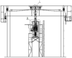
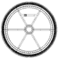
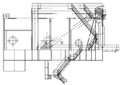
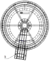
The object of the invention is realized by the following technical programs: method for dismounting is supported in a kind of crane barge revolution; May further comprise the steps: at first carry out the preparation before removing: jib is placed on the jib shelf; To turn round anchor and put down, the anti-piece of carving that inclines between structure and the revolution support lower railway in front portion will be carved tightly; Remove cylinder inner cable, tube connector then: will draw the cable that is installed on the centre collector ring from reversing chassis and remove; And from cylinder revolution bracing frame, all move in the crossbeam of reversing chassis center the cable fag end fixing; Then with flameproof fabric etc. with the protection of cable parcel, prevent damage in the construction; Tube connector in the centre collector ring is pulled down; Earlier tube connector and reversing chassis junction are severed during dismounting; Must not injure the reversing chassis mother metal when severing; After severing tube connector and shaft coupling connecting bolt are removed, then tube connector are placed on the centre collector ring support and fix, with protective cloth with centre collector ring parcel protection (as shown in Figure 1); Remove inclined ladder, roller and rolling wheel support: remove roller and rolling wheel support on the corresponding lower railway of reversing chassis front and back support rail beam gap; Winching to the appointed place then also notes protecting; Treat all to restore (as shown in Figure 2) after revolution support replacing finishes; Inclined ladder is removed, and treats to restore (as shown in Figure 3) after revolution support replacing finishes; Build the slide rail platform, on the standing part cylinder, build technique platform and slide rail (as shown in Figure 4); To turn round and support jacking, shift out: remove the bolt that is connected between the bolt (as shown in Figure 5) that is connected between oil groove on the revolution bracing frame, bearing outer ring bearing and the reversing chassis, revolution bracing frame and the turntable; After disassembling bolts between bearing outer ring bearing and the central shaft connecting plate finishes, the bearing outer ring bearing is ejected (as shown in Figure 6) from the central shaft connecting plate with jack; Old revolution supporting traction to slide rail, is moved on to the outside, lift ground (as shown in Figure 7) then; New revolution support is lifted on the slide rail, be drawn to the installation site, be in place (as shown in Figure 8).
The present invention compared with prior art has the following advantages:
Through the method crane barge revolution support is removed, practiced thrift human and material resources, financial resources greatly, and saved valuable time.
Description of drawings:
Fig. 1 is a centre collector ring supporting structure scheme drawing;
Fig. 2 supports for revolution and changes the aft ramp platform structure scheme drawing that finishes;
Fig. 3 supports the structural representation after changing for revolution;
Fig. 4 is a slide rail platform structure scheme drawing;
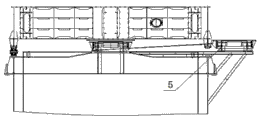
Fig. 5 is for removing the structural representation of oil groove, bolt;
The structural representation that Fig. 6 ejects the outside race bearing for jack;
Fig. 7 supports for revolution and lifts ground-surface structural representation;
Fig. 8 supports for new revolution and installs to the bit architecture scheme drawing;
Label among the figure: 1-connection pipe, 2-centre collector ring, 3-slide rail platform, the old revolution of 4-are supported, 5-newly turns round support.
The specific embodiment:
In order to deepen to understanding of the present invention, will combine embodiment that the present invention is made further detailed description below, this embodiment only is used to explain the present invention, does not constitute the qualification to protection domain of the present invention.
A kind of specific embodiment of unit assembling method of large-size gantry crane of the present invention may further comprise the steps:
Preparation before at first removing is placed into jib on the jib shelf, will turn round anchor and put down, and the anti-piece of carving that inclines between structure and the revolution support lower railway in front portion is carved tightly; Remove cylinder inner cable, connection pipe 1 etc. again; To draw from reversing chassis and be installed on the centre collector ring 2 cable and remove; And from cylinder revolution bracing frame, all move the cable fag end to reversing chassis center crossbeam internal fixation; Then with asbeston etc. with the protection of cable parcel, prevent damage in the construction; Connection pipe 1 in the centre collector ring 2 is pulled down, earlier connection pipe and reversing chassis junction are severed during dismounting, must not injure the reversing chassis mother metal when severing; After severing connection pipe and plunging joint tie bolt are removed; Be placed into connection pipe on the centre collector ring support then and fix; With protective cloth the centre collector ring parcel is protected; Remove inclined ladder, roller and rolling wheel support again, roller and rolling wheel support before and after the dismounting reversing chassis on the cooresponding lower railway of support rail beam gap winch to the appointed place then and attention protects, and wait to turn round support and change the whole recoveries in the back that finishes; Inclined ladder is removed, and treats to restore after revolution support replacing finishes; Build slide rail platform 3, on the fixed part cylinder, build technique platform and slide rail; To turn round and support jacking, shift out: remove bonded assembly bolt between oil groove, outside race bearing and the reversing chassis on the revolution bracing frame earlier, turn round bonded assembly bolt between bracing frame and the turntable; After disassembling bolts between outside race bearing and the center shaft connecting panel finishes, the outside race bearing is ejected from the center shaft connecting panel with jack; Again old revolution is supported 4 and be drawn on the slide rail, move on to the outside, lift ground then; New revolution is supported 5 lift on the slide rail, be drawn to the installation site, be in place.
Use this method to carry out the crane barge pivoting support and not only practiced thrift great amount of manpower and material resources, financial resources, and avoided deformation of members.
Claims (1)
1. method for dismounting is supported in a crane barge revolution, it is characterized in that: may further comprise the steps:
Prepare before A, the dismounting:
A, jib is placed on the jib shelf;
B, will turn round grappling and put down;
C, the piece of carving that front portion counter incline structure and revolution are supported between the lower railway are carved tightly;
B, dismounting cylinder inner cable, connection pipe etc.:
A, will draw the cable that is installed on the centre collector ring from reversing chassis and remove, and from cylinder revolution bracing frame, all move the cable fag end to reversing chassis center crossbeam internal fixation, then with asbeston etc. with the protection of cable parcel, prevent damage in the construction;
B, the connection pipe in the centre collector ring (1) is pulled down, earlier connection pipe (1) and reversing chassis junction are severed during dismounting, must not injure the reversing chassis mother metal when severing; After severing connection pipe (1) and plunging joint tie bolt are removed, be placed into connection pipe on centre collector ring (2) support then and fix;
C, with protective cloth with centre collector ring (2) parcel protection (Fig. 1);
C, dismounting inclined ladder, roller and rolling wheel support:
Roller and rolling wheel support before and after a, the dismounting reversing chassis on the cooresponding lower railway of support rail beam gap winch to the appointed place then and attention protects, and wait to turn round support and change the whole recoveries in back (Fig. 2) that finish;
B, the inclined ladder of position shown in Fig. 3 medium cloud line is removed, treated that revolution is supported to change the back that finishes and restore (Fig. 3);
D, build slide rail platform (3), on the fixed part cylinder, build technique platform and slide rail (Fig. 4);
E, will turn round and support jacking, shift out:
Bonded assembly bolt (Fig. 5) between bonded assembly bolt, revolution bracing frame and the turntable between oil groove, outside race bearing and the reversing chassis on a, the dismounting revolution bracing frame;
After disassembling bolts between b, outside race bearing and the center shaft connecting panel finishes, the outside race bearing is ejected (Fig. 6) from the center shaft connecting panel with jack;
C, (4) are supported in old revolution be drawn on the slide rail, move on to the outside, lift ground (Fig. 7) then;
D, (5) are supported in new revolution lifted on the slide rail, be drawn to the installation site, (Fig. 8) is in place.
Priority Applications (1)
| Application Number | Priority Date | Filing Date | Title |
|---|---|---|---|
| CN 201110250871 CN102311057B (en) | 2011-08-29 | 2011-08-29 | Floating crane revolving support dismounting method |
Applications Claiming Priority (1)
| Application Number | Priority Date | Filing Date | Title |
|---|---|---|---|
| CN 201110250871 CN102311057B (en) | 2011-08-29 | 2011-08-29 | Floating crane revolving support dismounting method |
Publications (2)
| Publication Number | Publication Date |
|---|---|
| CN102311057A true CN102311057A (en) | 2012-01-11 |
| CN102311057B CN102311057B (en) | 2013-04-17 |
Family
ID=45424678
Family Applications (1)
| Application Number | Title | Priority Date | Filing Date |
|---|---|---|---|
| CN 201110250871 Active CN102311057B (en) | 2011-08-29 | 2011-08-29 | Floating crane revolving support dismounting method |
Country Status (1)
| Country | Link |
|---|---|
| CN (1) | CN102311057B (en) |
Cited By (4)
| Publication number | Priority date | Publication date | Assignee | Title |
|---|---|---|---|---|
| CN103410104A (en) * | 2013-08-29 | 2013-11-27 | 上海市机械施工集团有限公司 | Method and device for replacing support of urban viaduct |
| CN103615469A (en) * | 2013-12-03 | 2014-03-05 | 上海振华重工(集团)股份有限公司 | Mounting components and dismounting method of large-sized slewing bearing |
| CN105252255A (en) * | 2015-09-10 | 2016-01-20 | 葛洲坝机械工业有限公司 | Method for replacing pivotal bearing of floating crane through jacking device |
| CN113104742A (en) * | 2021-04-14 | 2021-07-13 | 潘归强 | Steel structure tower crane for building bridge road construction |
Citations (2)
| Publication number | Priority date | Publication date | Assignee | Title |
|---|---|---|---|---|
| RU2338680C1 (en) * | 2007-04-16 | 2008-11-20 | Государственное образовательное учреждение высшего профессионального образования Марийский государственный технический университет | Support-rotating device |
| CN101607679A (en) * | 2009-07-16 | 2009-12-23 | 上海振华重工(集团)股份有限公司 | The roller elastic track slewing supporting device that is used for ultra-large type full circle swinging hoisting crane |
-
2011
- 2011-08-29 CN CN 201110250871 patent/CN102311057B/en active Active
Patent Citations (2)
| Publication number | Priority date | Publication date | Assignee | Title |
|---|---|---|---|---|
| RU2338680C1 (en) * | 2007-04-16 | 2008-11-20 | Государственное образовательное учреждение высшего профессионального образования Марийский государственный технический университет | Support-rotating device |
| CN101607679A (en) * | 2009-07-16 | 2009-12-23 | 上海振华重工(集团)股份有限公司 | The roller elastic track slewing supporting device that is used for ultra-large type full circle swinging hoisting crane |
Non-Patent Citations (3)
| Title |
|---|
| 张大国: "转柱式门机回转下支承轴承更换工艺及施工组织", 《港口装卸》 * |
| 范广澄: "用顶升法更换门机的下支承轴承", 《港口装卸》 * |
| 蒋祖光: "用顶升法更换浮式起重机回转支承轴承", 《港口装卸》 * |
Cited By (7)
| Publication number | Priority date | Publication date | Assignee | Title |
|---|---|---|---|---|
| CN103410104A (en) * | 2013-08-29 | 2013-11-27 | 上海市机械施工集团有限公司 | Method and device for replacing support of urban viaduct |
| CN103410104B (en) * | 2013-08-29 | 2015-10-28 | 上海市机械施工集团有限公司 | The bearing replacement method and apparatus of overhead road of city |
| CN103615469A (en) * | 2013-12-03 | 2014-03-05 | 上海振华重工(集团)股份有限公司 | Mounting components and dismounting method of large-sized slewing bearing |
| CN103615469B (en) * | 2013-12-03 | 2016-08-17 | 上海振华重工(集团)股份有限公司 | The method for dismounting of huge revolving bearing |
| CN105252255A (en) * | 2015-09-10 | 2016-01-20 | 葛洲坝机械工业有限公司 | Method for replacing pivotal bearing of floating crane through jacking device |
| CN105252255B (en) * | 2015-09-10 | 2017-08-01 | 中国葛洲坝集团机械船舶有限公司 | A kind of method that floating crane floating bearing is changed with jacking apparatus |
| CN113104742A (en) * | 2021-04-14 | 2021-07-13 | 潘归强 | Steel structure tower crane for building bridge road construction |
Also Published As
| Publication number | Publication date |
|---|---|
| CN102311057B (en) | 2013-04-17 |
Similar Documents
| Publication | Publication Date | Title |
|---|---|---|
| CN102464273B (en) | Offshore fan installing platform and fan integral installation rotary holding and lifting mechanism | |
| CN101880006B (en) | Roll-on device and method for large fixed type rotary crane | |
| CN102102344B (en) | Method for quickly assembling assembled corrugated culvert | |
| JP4159933B2 (en) | Repair methods and equipment for wind power towers, etc. | |
| CN102311057B (en) | Floating crane revolving support dismounting method | |
| CN111472797A (en) | Implementation method for detaching TBM in hole | |
| CN204474178U (en) | A kind of cable crane | |
| CN102486051B (en) | Manual demolishing method of large-area spherical net rack | |
| CN112265616A (en) | Propeller disassembling method, propeller installing method and propeller disassembling tool | |
| CN211343235U (en) | Maintenance tool on gearbox tower of wind driven generator | |
| CN102530582A (en) | Method for landing large-size ship loader entirely | |
| CN110758421A (en) | Vehicle maintenance vehicle suitable for air rail transit system | |
| CN110145317A (en) | A kind of technique on shield machine's station-crossing construction method | |
| CN212475766U (en) | Plate hoisting equipment | |
| CN110306420B (en) | Pipe transportation device in pipe bridge and construction method thereof | |
| CN113818478A (en) | Overweight prefabricated pipe gallery installation system and construction method thereof | |
| CN202098670U (en) | Wind turbine tower conveying and elevating auxiliary device | |
| CN204369434U (en) | Prefabricated non-slag rail plate air turning device | |
| CN218716794U (en) | TBM lossless dismantling device under existing cavern condition | |
| CN105671245A (en) | Method for inversely mounting revolving furnace through winch | |
| CN211004358U (en) | Special equipment for disassembling and installing hydraulic support | |
| CN214650184U (en) | Novel pressure steel pipe transportation jacking integrated trolley structure | |
| CN114134817B (en) | Dismounting method and mounting method of segment bridging machine | |
| CN218813232U (en) | Auxiliary mounting, dismounting and fixing device for prestressed box girder tensioning jack | |
| CN210713871U (en) | Self-moving support frame of discharging platform |
Legal Events
| Date | Code | Title | Description |
|---|---|---|---|
| C06 | Publication | ||
| PB01 | Publication | ||
| C10 | Entry into substantive examination | ||
| SE01 | Entry into force of request for substantive examination | ||
| C14 | Grant of patent or utility model | ||
| GR01 | Patent grant | ||
| C41 | Transfer of patent application or patent right or utility model | ||
| TR01 | Transfer of patent right |
Effective date of registration: 20170227 Address after: The 226000 farm of Jiangsu province Nantong Development Zone Riverview Road No. 1 Patentee after: Nantong Zhenhua Heavy Equipment Manufacturing Co., Ltd. Address before: Jiangsu Zhenhua 226000 city of Nantong Province Economic and Technological Development Zone Nantong Road No. 1 Patentee before: Shanghai Zhenhua Heavy Industry Group (Nantong) Co., Ltd. |