CN102230381B - Hollow needle beam lining trolley - Google Patents
Hollow needle beam lining trolley Download PDFInfo
- Publication number
- CN102230381B CN102230381B CN 201110147182 CN201110147182A CN102230381B CN 102230381 B CN102230381 B CN 102230381B CN 201110147182 CN201110147182 CN 201110147182 CN 201110147182 A CN201110147182 A CN 201110147182A CN 102230381 B CN102230381 B CN 102230381B
- Authority
- CN
- China
- Prior art keywords
- needle beam
- screw mandrel
- side form
- slippage frame
- backform
- Prior art date
- Legal status (The legal status is an assumption and is not a legal conclusion. Google has not performed a legal analysis and makes no representation as to the accuracy of the status listed.)
- Active
Links
Images
Landscapes
- Lining And Supports For Tunnels (AREA)
- Conveying And Assembling Of Building Elements In Situ (AREA)
Abstract
The invention disclosed a hollow needle beam lining trolley. A needle beam (10) has a box beam structure with an intermediate preformed hole (35); both ends of the needle beam (10) are respectively provided with a main landing leg (16); the lower end of the main landing leg (16) is provided with a jacking oil cylinder (24) and a first load-bearing screw rod (33); one end of the needle beam (10) is provided with a hoisting machine (23); the other end of the needle beam (10) is provided with a guide pulley (29); a slide bracket (13) is sleeved on the needle beam (10); the upper end of the slide bracket (13) is provided with a travelling hanging wheel (9) and the lower end of the slide bracket (13) is provided with a travelling supporting wheel (12) in sliding touch with the needle beam (10); a template system is arranged on the slide bracket (13); and the front end of the template system is provided with a front hook (27) and the rear end of the template system is provided with a rear hook (28). According to the invention, a hollow design is adopted in the needle beam so as to effectively solve the ventilation problem of small section tunnels; the landing legs are arranged outside the template so that the traffic capacity of tunnel construction equipment is greatly increased; no steel rail is needed to be paved, thus the labor intensity is lower; and the traditional trolley main frame is canceled, thus the operation is more convenient.
Description
Technical field
The present invention relates to a kind of template equipment that is specifically designed to Tunnel Second Lining Construction, exactly is a kind of hollow needle beam lining trolley that is applicable to the light section medium tunnel engineering constructions such as railway, highway, water conservancy, municipal administration.
Background technology
The lining trolley that uses in constructing tunnel at present mainly is comprised of portal frame support system, template system, hydraulic operating system, electric speed reducing running gear and other accessory system.The portal frame support system is comprised of lower longeron, column, door frame crossbeam, Eight characters bearing diagonal and support screw, and its Main Function is that other assembly of chassis is installed, and bears construction load, prevents template race mould; Template system is comprised of backform and side form, and its effect is to guarantee the forming surface size; Hydraulic system is comprised of pumping plant, pipeline, operating valve and oil cylinder, its effect is to transfer chassis formwork erection and the demoulding, running gear is comprised of road wheel, motor, reductor, and its effect is mobile trolley used, and other accessory system mainly contains the booster action members such as workbench, ladder, screw mandrel.
This type lining trolley Heavy Weight, cost is high, rigidity is large, has certain advantage in the large cross-section tunnel construction, but in the construction of middle narrow-bore tunnel a lot of shortcomings is arranged, mainly contain following some:
One, trolley supporting system complex structure, member is many, and large-scale air pipeline can't pass through, and ventilation condition is poor, has worsened construction environment.
Two, template and body frame have occupied larger space, thereby the portal frame headroom is less, and the traffic capacity is poor, and it is current to satisfy large-scale construction equipment equipment, thereby can only select mini-plant to affect progress.
Three, the distance between template and the gantry pillar is too little, and the interventional operations rod member is many, seriously restricts and have influence on staff's construction.
Four, adopt the rail mounted walking, must lay in advance track before the walking, track manually must be moved forward after the walking, labour intensity is large, inefficiency.
Summary of the invention
Technical problem to be solved by this invention provides a kind of current and air-conditioning requirement of heavy construction equipment that is suitable for satisfying simultaneously in the narrow-bore tunnel construction, and operation is very easy, the hollow needle beam lining trolley of high efficiency.
In order to address the above problem, hollow needle beam lining trolley provided by the invention, comprise template system and hydraulic system, needle beam is the box-beam structure of preformed hole in the middle of being provided with, main supporting leg is equipped with respectively at the two ends of described needle beam, the lower end of described main supporting leg is provided with jacking cylinder and the first load-bearing screw mandrel, described needle beam one end is equipped with hoist engine, the other end is equipped with leading block, the slippage frame is sleeved on the described needle beam and described slippage frame upper end is equipped with the walking change gear, the lower end is equipped with walking support roller and described needle beam sliding-contact, described template system is installed on the described slippage frame, and described template system front end is provided with front hook, and the rear end is provided with aft hook.
Described template system is comprised of a backform and symmetrically arranged two side forms, and every described side form arc gusset is provided with four, becomes box girder structure with panel and arc plate assembly welding, and described side form connects by oil cylinder with described slippage frame; Described backform is by upper longeron, slip cap connects with described slippage frame, between described upper longeron and the described slippage frame translation oil cylinder is installed, described side form and described backform are by the whole work plane of the hinged formation of pin, described side form and described backform are affixed by the first screw mandrel during duty, be provided with the second screw mandrel between described backform and the described slippage frame, every described side form and described slippage frame are by the 3rd screw mandrel, the 4th screw mandrel connects with the 5th screw mandrel, every described side form bottom is provided with support screw and oblique top screw mandrel, and the side is provided with collapsible workbench.
Move in the front end of described needle beam or rear end and to be provided with an auxiliary supporting leg, the lower end of described auxiliary supporting leg is provided with the second load-bearing screw mandrel.
Described side form and backform form ring-type, and every ring width is between the 1.5-2 rice, and whole chassis becomes whole by many rings template by Bolt Connection as required.
Described needle beam is provided with work stair and working platform.
Described hydraulic system is comprised of the Main Hydraulic Pump station that is located at the hydraulic power unit on the described needle beam and be located on the described travelling carriage.
Adopt the hollow needle beam lining trolley of technique scheme, needle beam is arranged on main supporting leg upper end, main supporting leg stands on the ground surface through jacking cylinder, template system is installed on the needle beam by slippage cover and support screw, oil cylinder, road wheel is installed in slippage and puts, hoist engine is installed on the needle beam, and two cover live hydraulic systems are installed in respectively on needle beam and the template system.The side form main gusset is designed with four, and two one group becomes box girder structure with panel and arc plate assembly welding, is used for bearing lateral pressure, and bottom design has support screw, is used for bearing vertical pressure.The backform main gusset adopts two common designs, and side form and backform are by the whole work plane of the hinged formation of pin, and side form and backform are affixed by screw mandrel during duty.The slippage frame is connected with backform, connects by oil cylinder, screw mandrel with side form.Support roller and change gear are installed on the slippage frame, are used for support shuttering system and needle beam system.The box-beam structure of preformed hole in the middle of needle beam is designed to is formed by steel plate installed-welded, the middle preformed hole construction air pipeline that is used for passing through tunnel, also can be directly as the part of air pipeline.The case beam is used for bearing template system and as the trolley running track.Main supporting leg is equipped with at the needle beam two ends, and jacking cylinder is housed on the supporting leg, is used for adjusting the needle beam height.Needle beam adopts hollow design, is formed by steel plate butt welding, has guaranteed on the one hand the intensity of needle beam, the air pipeline passage is provided again on the other hand, thereby has satisfied air-conditioning requirement, has improved construction environment.Hoist engine provides power for the walking of needle beam and template, and support roller is used for the template system walking.Change gear is used for the walking of needle beam system.Hydraulic system comprises pumping plant, pipeline, control valve and oil cylinder.To the damage of pipeline, this product design becomes two independent cover hydraulic systems during for minimizing template system and needle beam system's relative motion.Oil cylinder is designed with jacking cylinder, translation oil cylinder, its effect be respectively adjust about the chassis, position, the left and right sides and the napex demoulding.The side direction oil cylinder is used for the side form demoulding.
In sum, the invention has the advantages that:
1, template system adopts reinforcement side form self intensity to bear the construction lateral pressure, ground, side form top screw mandrel bears vertical pressure, needle beam bears the method for designing of vertical pressure, cancelled traditional lining trolley portal frame support system, the needle beam supporting leg take laterally and side template overlapping, vertically not overlapping, saved to greatest extent the space that lining trolley self takies, thereby improved the traffic capacity, reached and satisfy the current purpose of heavy construction equipment
2, needle beam adopts hollow design in the needle beam system, is formed by steel plate butt welding, has guaranteed on the one hand the intensity of needle beam, the air pipeline passage is provided again on the other hand, thereby has satisfied air-conditioning requirement, has improved construction environment.
3, the following side form part of needle beam only is designed with row's support screw, without other obstacle rod member, thus more convenient operation.
4, the walking design is taked in walking, no longer needs steel sleeper during walking, and labour intensity reduces greatly, and operating efficiency improves greatly.
Description of drawings
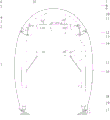
Fig. 1 is hollow needle beam lining trolley front view of the present invention;
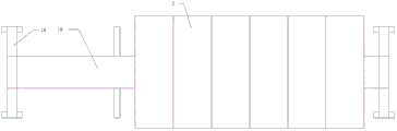
Fig. 2 is hollow needle beam lining trolley top view of the present invention;
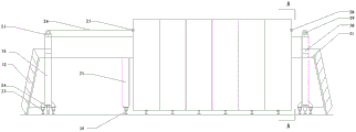
Fig. 3 is hollow needle beam lining trolley lateral view of the present invention;
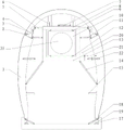
Fig. 4 is along A-A line cross-sectional schematic among Fig. 3.
The specific embodiment
The utility model is described in further detail below in conjunction with the drawings and specific embodiments.
Referring to Fig. 1, Fig. 2, Fig. 3 and Fig. 4, needle beam 10 is the box-beam structure of preformed hole 35 in the middle of being provided with, formed by steel plate installed-welded, main supporting leg 16 is equipped with respectively at the two ends of needle beam 10, the lower end of main supporting leg 16 is provided with jacking cylinder 24 and the first load-bearing screw mandrel 33, needle beam 10 1 ends are equipped with hoist engine 23, the other end is equipped with leading block 29, slippage frame 13 is sleeved on the needle beam 10 and slippage frame 13 upper ends are equipped with walking change gear 9, the lower end is equipped with walking support roller 12 and needle beam 10 sliding-contacts, template system is comprised of a backform 3 and symmetrically arranged two side forms 1, side form 1 and backform 3 form ring-type, every ring width is between the 1.5-2 rice, whole chassis becomes whole by many rings template by Bolt Connection as required, every side form 1 arc gusset is provided with four, become box girder structure with panel and arc plate assembly welding, side form 1 connects by oil cylinder 22 with slippage frame 13; Backform 3 is by upper longeron 6, slip cap 8 connects with slippage frame 13, between upper longeron 6 and the slippage frame 13 translation oil cylinder 7 is installed, side form 1 and backform 3 are by the whole work plane of pin 2 hinged formation, side form 1 and backform 3 are affixed by the first screw mandrel 4 during duty, be provided with the second screw mandrel 5 between backform 3 and the slippage frame 13, every side form 1 passes through the 3rd screw mandrel 11 with slippage frame 13, the 4th screw mandrel 21 connects with the 5th screw mandrel 14, every side form 1 bottom is provided with support screw 19 and oblique top screw mandrel 18, the side is provided with collapsible workbench 15, the template system front end is provided with front hook 27, and the rear end is provided with aft hook 28; Front end or rear end at needle beam 10 are provided with the auxiliary supporting leg 25 that an energy moves at needle beam 10, the lower end of auxiliary supporting leg 25 is provided with the second load-bearing screw mandrel 34, needle beam 10 is provided with work stair 32 and working platform 31, hydraulic power unit 30 on needle beam 10, the Main Hydraulic Pump station 20 on travelling carriage 13 forms.
Referring to Fig. 1, Fig. 2, Fig. 3 and Fig. 4, this product is installed in the tunneling position (also can be by being installed in first outside the hole, move on to the operating position by following described trolley running method again), the tunnel ventilation pipeline is passed from the hollow needle beam endoporus, then as follows operation:
One, chassis formwork erection operation
1, start Main Hydraulic Pump station 20, operate respectively two translation oil cylinders 7, test desk roof mould 3 front and back section center lines are until center line and tunnel central lines.
2, start hydraulic power unit 30, operate respectively four jacking cylinders 24, test desk roof mould 3 pin joint absolute altitudes and peak absolute altitude are until satisfy design elevation.
3, the first load-bearing screw mandrel 33 is held out against.
4, operate respectively four oil cylinders 22, side form 1 and the little wall 17 of crossing are adjacent to.
5, with the first screw mandrel 4, the second screw mandrel 5, the three screw mandrels 11, the 4th screw mandrel 21 and the 5th screw mandrel 14, oblique top screw mandrel 18, support screw 19 holds out against, and position-limited rack holds out against.
6, will assist supporting leg 25 to move near template position, the second load-bearing screw mandrel 34 will be held out against.
7, beginning lining cutting operation behind the installation plug.
Two, chassis stripping operation
1, takes down oblique top screw mandrel 18 and support screw 19, the three screw mandrel 11, the five screw mandrels, 14, the four screw mandrels 21 and the first screw mandrels 4.
2, start Main Hydraulic Pump station 20, operate respectively four oil cylinders 22, make side form 1 break away from the concrete surface certain distance.Reinstall the first screw mandrel 4, the five screw mandrels 14, the four screw mandrels 21 that backform 3 and side form 1 connect.
3, start hydraulic power unit 30, operate respectively four jacking cylinders 24, make about the whole decline 100mm of trolley formwork.Any position of trolley formwork this moment all can not contact with ground, concrete and obstruction.
Three, trolley running operation
1, starts hoist engine 23, template is moved forward at needle beam 10 under the pulling force of hoist engine, stop behind the arrival certain position.
2, start hydraulic power unit 30, operate respectively four jacking cylinders 24, trolley formwork integral body is landed, continue to operate respectively four jacking cylinders 24, make about main supporting leg 16 liftoff 200mm.
3, take down the wire rope 26 of the front hook 27 on the template, by directive wheel 29, wire rope 26 is fixed on the aft hook 28 on the template.
4, start hoist engine 23, needle beam 10 is moved forward at slippage frame 13 under the pulling force of hoist engine 23, stop after arriving certain position.
If 5 process aforesaid operations also do not arrive the destination, can then repeat 1 to 4 operation first by 6 operations, so repeatedly, reach destination locations until get home.
6, start hydraulic power unit 30, operate respectively four jacking cylinders 24, stretch out the first load-bearing screw mandrel 33, until about the whole liftoff 200mm of trolley formwork.Any position of trolley formwork this moment all can not contact with ground, concrete and obstruction.
Claims (5)
1. hollow needle beam lining trolley, comprise template system and hydraulic system, needle beam (10) is the box-beam structure of preformed hole (35) in the middle of being provided with, main supporting leg (16) is equipped with respectively at the two ends of described needle beam (10), the lower end of described main supporting leg (16) is provided with jacking cylinder (24) and the first load-bearing screw mandrel (33), described needle beam (10) one ends are equipped with hoist engine (23), the other end is equipped with leading block (29), slippage frame (13) is sleeved on described needle beam (10) upward and described slippage frame (13) upper end is equipped with walking change gear (9), the lower end is equipped with walking support roller (12) and described needle beam (10) sliding-contact, it is characterized in that: described template system is installed on the described slippage frame (13), described template system front end is provided with front hook (27), the rear end is provided with aft hook (28), described template system is comprised of a backform (3) and symmetrically arranged two side forms (1), every described side form (1) arc gusset is provided with four, become box girder structure with panel and arc plate assembly welding, described side form (1) connects by oil cylinder (22) with described slippage frame (13); Described backform (3) is by upper longeron (6), slip cap (8) connects with described slippage frame (13), between described upper longeron (6) and the described slippage frame (13) translation oil cylinder (7) is installed, described side form (1) and described backform (3) are by the whole work plane of the hinged formation of pin (2), described side form (1) and described backform (3) are affixed by the first screw mandrel (4) during duty, be provided with the second screw mandrel (5) between described backform (3) and the described slippage frame (13), every described side form (1) passes through the 3rd screw mandrel (11) with described slippage frame (13), the 4th screw mandrel (21) connects with the 5th screw mandrel (14), every described side form (1) bottom is provided with support screw (19) and oblique top screw mandrel (18), and the side is provided with collapsible workbench (15).
2. hollow needle beam lining trolley according to claim 1 is characterized in that: move in the front end of described needle beam (10) or rear end and be provided with an auxiliary supporting leg (25), the lower end of described auxiliary supporting leg (25) is provided with the second load-bearing screw mandrel (34).
3. hollow needle beam lining trolley according to claim 1 is characterized in that: described side form (1) and backform (3) form ring-type, and every ring width is between the 1.5-2 rice, and whole chassis becomes whole by many rings template by Bolt Connection as required.
4. hollow needle beam lining trolley according to claim 1, it is characterized in that: described needle beam (10) is provided with work stair (32) and working platform (31).
5. hollow needle beam lining trolley according to claim 1, it is characterized in that: described hydraulic system is comprised of the Main Hydraulic Pump station (20) that is located at the hydraulic power unit (30) on the described needle beam (10) and be located on the described slippage frame (13).
Priority Applications (1)
| Application Number | Priority Date | Filing Date | Title |
|---|---|---|---|
| CN 201110147182 CN102230381B (en) | 2011-06-02 | 2011-06-02 | Hollow needle beam lining trolley |
Applications Claiming Priority (1)
| Application Number | Priority Date | Filing Date | Title |
|---|---|---|---|
| CN 201110147182 CN102230381B (en) | 2011-06-02 | 2011-06-02 | Hollow needle beam lining trolley |
Publications (2)
| Publication Number | Publication Date |
|---|---|
| CN102230381A CN102230381A (en) | 2011-11-02 |
| CN102230381B true CN102230381B (en) | 2013-03-20 |
Family
ID=44842980
Family Applications (1)
| Application Number | Title | Priority Date | Filing Date |
|---|---|---|---|
| CN 201110147182 Active CN102230381B (en) | 2011-06-02 | 2011-06-02 | Hollow needle beam lining trolley |
Country Status (1)
| Country | Link |
|---|---|
| CN (1) | CN102230381B (en) |
Cited By (1)
| Publication number | Priority date | Publication date | Assignee | Title |
|---|---|---|---|---|
| CN105569687A (en) * | 2015-12-14 | 2016-05-11 | 中铁四局集团第一工程有限公司 | Gantry supporting structure for tunnel lining trolley |
Families Citing this family (7)
| Publication number | Priority date | Publication date | Assignee | Title |
|---|---|---|---|---|
| CN104018854B (en) * | 2014-06-26 | 2016-03-23 | 湖南五新隧道智能装备股份有限公司 | A kind of city gate type needle beam trolley |
| CN104153791A (en) * | 2014-08-11 | 2014-11-19 | 中铁建大桥工程局集团第六工程有限公司 | Assembly trolley for prefabricated assembly type subway station |
| CN106194208B (en) * | 2015-05-06 | 2019-04-16 | 四川睿铁科技有限责任公司 | A kind of tunnel lining trolley with ventilation duct |
| CN107448218A (en) * | 2017-09-26 | 2017-12-08 | 中铁十七局集团第工程有限公司 | A kind of single-track tunnel lining trolley constructing device |
| CN108386219B (en) * | 2018-04-18 | 2023-08-11 | 招商局重庆交通科研设计院有限公司 | Supporting system of tunnel supporting structure and operation method |
| CN111379569B (en) * | 2018-12-27 | 2021-06-18 | 山河智能装备股份有限公司 | Lining trolley without portal |
| CN111379575B (en) * | 2020-05-11 | 2021-03-26 | 温州安荷桥科技有限公司 | Tunnel lining trolley |
Citations (6)
| Publication number | Priority date | Publication date | Assignee | Title |
|---|---|---|---|---|
| DE3040354A1 (en) * | 1980-10-25 | 1982-05-06 | Klöckner-Becorit GmbH, 4620 Castrop-Rauxel | KNIFE SHIELD FOR THE FULL EXTENSION OF A ROUTE |
| CN201196094Y (en) * | 2008-05-22 | 2009-02-18 | 中铁十一局集团第一工程有限公司 | Hydraulic template trolley for rail tunnel liner concrete |
| CN101403305A (en) * | 2008-09-08 | 2009-04-08 | 中铁隧道集团有限公司 | Construction method for tunnel continuous mucking, lining and excavation synchronization |
| CN201496071U (en) * | 2009-06-24 | 2010-06-02 | 文同轩 | Trestle bridge type circular needle beam trolley |
| CN201554467U (en) * | 2009-11-24 | 2010-08-18 | 广汉金达隧道机械有限公司 | Overhead needle beam hydraulic steel mould trolley |
| CN201560771U (en) * | 2009-12-14 | 2010-08-25 | 中铁隧道集团二处有限公司 | TBM (Tunnel Boring Machine) synchronous lining mould plate trolley and bench |
-
2011
- 2011-06-02 CN CN 201110147182 patent/CN102230381B/en active Active
Patent Citations (6)
| Publication number | Priority date | Publication date | Assignee | Title |
|---|---|---|---|---|
| DE3040354A1 (en) * | 1980-10-25 | 1982-05-06 | Klöckner-Becorit GmbH, 4620 Castrop-Rauxel | KNIFE SHIELD FOR THE FULL EXTENSION OF A ROUTE |
| CN201196094Y (en) * | 2008-05-22 | 2009-02-18 | 中铁十一局集团第一工程有限公司 | Hydraulic template trolley for rail tunnel liner concrete |
| CN101403305A (en) * | 2008-09-08 | 2009-04-08 | 中铁隧道集团有限公司 | Construction method for tunnel continuous mucking, lining and excavation synchronization |
| CN201496071U (en) * | 2009-06-24 | 2010-06-02 | 文同轩 | Trestle bridge type circular needle beam trolley |
| CN201554467U (en) * | 2009-11-24 | 2010-08-18 | 广汉金达隧道机械有限公司 | Overhead needle beam hydraulic steel mould trolley |
| CN201560771U (en) * | 2009-12-14 | 2010-08-25 | 中铁隧道集团二处有限公司 | TBM (Tunnel Boring Machine) synchronous lining mould plate trolley and bench |
Cited By (1)
| Publication number | Priority date | Publication date | Assignee | Title |
|---|---|---|---|---|
| CN105569687A (en) * | 2015-12-14 | 2016-05-11 | 中铁四局集团第一工程有限公司 | Gantry supporting structure for tunnel lining trolley |
Also Published As
| Publication number | Publication date |
|---|---|
| CN102230381A (en) | 2011-11-02 |
Similar Documents
| Publication | Publication Date | Title |
|---|---|---|
| CN102230381B (en) | Hollow needle beam lining trolley | |
| CN201077721Y (en) | Gantry crane with falling girder | |
| CN102296971B (en) | Lining method for tunnel emergency turnout strips and tunnel-lining trolley | |
| CN109914166B (en) | Urban rail scattered paving method mechanized construction equipment and construction method thereof | |
| CN203199912U (en) | Folding gantry crane | |
| CN206092022U (en) | Be used for lining cutting rectangular -section or radiation gradual change rectangular -section formula operation car of crawling | |
| CN207498755U (en) | A kind of traveling trolley adjusted with horizontal extension and vertical supporting | |
| CN201474704U (en) | Needle beam type hydraulic steel mould carrier | |
| CN102337905B (en) | Open type TBM (Tunnel Boring Machine) fullface synchronous lining trolley for hydraulictunnel | |
| CN103016028A (en) | Hydraulic self-propelled steel form carrier for tunnel secondary lining operation | |
| CN104747078A (en) | Tunnel construction trolley | |
| CN203021883U (en) | Wheel-track railway track laying unit | |
| CN103726421A (en) | Height and span adjustable track paver for metro construction | |
| CN104179090A (en) | Subway rail laying system | |
| CN103074829A (en) | Railway switch changing construction method and railway switch track laying unit thereof | |
| CN107762552B (en) | The rapid translation trolley and method of mating trailer after TBM | |
| CN204703761U (en) | A kind of tunnel construction trolley | |
| CN109295999A (en) | Prefabricated assembled pipe gallery fitting machine and its construction method | |
| CN201933415U (en) | Highway and railway twin-girder bridge erection machine | |
| CN101967798B (en) | Highway double-guide-beam bridge erecting machine and turning method | |
| CN201627144U (en) | Double-beam transportation and erection integrated bridge girder erection machine | |
| CN203702178U (en) | Bottom end supercharged type small-height tunnel lining trolley | |
| CN204023336U (en) | A kind of subway track-laying machine | |
| CN212222234U (en) | Double-girder subway track laying machine | |
| CN201801817U (en) | Highway double-guide beam bridge erecting machine |
Legal Events
| Date | Code | Title | Description |
|---|---|---|---|
| C06 | Publication | ||
| PB01 | Publication | ||
| C10 | Entry into substantive examination | ||
| SE01 | Entry into force of request for substantive examination | ||
| C14 | Grant of patent or utility model | ||
| GR01 | Patent grant |