CN102213552B - Non-ferrous metal melt pump and melting furnace system using same - Google Patents
Non-ferrous metal melt pump and melting furnace system using same Download PDFInfo
- Publication number
- CN102213552B CN102213552B CN201110063647.5A CN201110063647A CN102213552B CN 102213552 B CN102213552 B CN 102213552B CN 201110063647 A CN201110063647 A CN 201110063647A CN 102213552 B CN102213552 B CN 102213552B
- Authority
- CN
- China
- Prior art keywords
- ferrous metal
- molten non
- magnetic field
- field device
- molten
- Prior art date
- Legal status (The legal status is an assumption and is not a legal conclusion. Google has not performed a legal analysis and makes no representation as to the accuracy of the status listed.)
- Expired - Fee Related
Links
- 229910052751 metal Inorganic materials 0.000 title claims abstract description 122
- 239000002184 metal Substances 0.000 title claims abstract description 122
- 238000002844 melting Methods 0.000 title claims abstract description 18
- 230000008018 melting Effects 0.000 title claims abstract description 18
- CWYNVVGOOAEACU-UHFFFAOYSA-N Fe2+ Chemical compound [Fe+2] CWYNVVGOOAEACU-UHFFFAOYSA-N 0.000 claims abstract description 116
- 239000007788 liquid Substances 0.000 claims description 38
- 230000000630 rising effect Effects 0.000 claims description 20
- 239000012530 fluid Substances 0.000 claims description 16
- 230000002706 hydrostatic effect Effects 0.000 claims description 16
- 238000007789 sealing Methods 0.000 claims description 5
- 230000005540 biological transmission Effects 0.000 claims description 3
- 230000009977 dual effect Effects 0.000 claims description 3
- 230000000149 penetrating effect Effects 0.000 abstract description 2
- 238000010079 rubber tapping Methods 0.000 abstract 1
- 238000010586 diagram Methods 0.000 description 9
- 238000000034 method Methods 0.000 description 8
- 239000004020 conductor Substances 0.000 description 4
- 238000001816 cooling Methods 0.000 description 3
- 238000005516 engineering process Methods 0.000 description 3
- 239000000463 material Substances 0.000 description 3
- 229910000861 Mg alloy Inorganic materials 0.000 description 2
- 229910045601 alloy Inorganic materials 0.000 description 2
- 239000000956 alloy Substances 0.000 description 2
- 229910052782 aluminium Inorganic materials 0.000 description 2
- 229910052802 copper Inorganic materials 0.000 description 2
- -1 ferrous metals Chemical class 0.000 description 2
- 238000012423 maintenance Methods 0.000 description 2
- 239000011819 refractory material Substances 0.000 description 2
- 229910052725 zinc Inorganic materials 0.000 description 2
- 229920000049 Carbon (fiber) Polymers 0.000 description 1
- 208000027418 Wounds and injury Diseases 0.000 description 1
- 230000015572 biosynthetic process Effects 0.000 description 1
- 239000004917 carbon fiber Substances 0.000 description 1
- 230000001276 controlling effect Effects 0.000 description 1
- 230000006378 damage Effects 0.000 description 1
- 238000005470 impregnation Methods 0.000 description 1
- 208000014674 injury Diseases 0.000 description 1
- 238000009434 installation Methods 0.000 description 1
- 239000011810 insulating material Substances 0.000 description 1
- VNWKTOKETHGBQD-UHFFFAOYSA-N methane Chemical compound C VNWKTOKETHGBQD-UHFFFAOYSA-N 0.000 description 1
- NJPPVKZQTLUDBO-UHFFFAOYSA-N novaluron Chemical compound C1=C(Cl)C(OC(F)(F)C(OC(F)(F)F)F)=CC=C1NC(=O)NC(=O)C1=C(F)C=CC=C1F NJPPVKZQTLUDBO-UHFFFAOYSA-N 0.000 description 1
- 230000001105 regulatory effect Effects 0.000 description 1
Images


Classifications
-
- F—MECHANICAL ENGINEERING; LIGHTING; HEATING; WEAPONS; BLASTING
- F27—FURNACES; KILNS; OVENS; RETORTS
- F27D—DETAILS OR ACCESSORIES OF FURNACES, KILNS, OVENS OR RETORTS, IN SO FAR AS THEY ARE OF KINDS OCCURRING IN MORE THAN ONE KIND OF FURNACE
- F27D3/00—Charging; Discharging; Manipulation of charge
- F27D3/14—Charging or discharging liquid or molten material
-
- C—CHEMISTRY; METALLURGY
- C22—METALLURGY; FERROUS OR NON-FERROUS ALLOYS; TREATMENT OF ALLOYS OR NON-FERROUS METALS
- C22B—PRODUCTION AND REFINING OF METALS; PRETREATMENT OF RAW MATERIALS
- C22B21/00—Obtaining aluminium
- C22B21/0084—Obtaining aluminium melting and handling molten aluminium
-
- C—CHEMISTRY; METALLURGY
- C22—METALLURGY; FERROUS OR NON-FERROUS ALLOYS; TREATMENT OF ALLOYS OR NON-FERROUS METALS
- C22B—PRODUCTION AND REFINING OF METALS; PRETREATMENT OF RAW MATERIALS
- C22B9/00—General processes of refining or remelting of metals; Apparatus for electroslag or arc remelting of metals
- C22B9/003—General processes of refining or remelting of metals; Apparatus for electroslag or arc remelting of metals by induction
-
- C—CHEMISTRY; METALLURGY
- C22—METALLURGY; FERROUS OR NON-FERROUS ALLOYS; TREATMENT OF ALLOYS OR NON-FERROUS METALS
- C22B—PRODUCTION AND REFINING OF METALS; PRETREATMENT OF RAW MATERIALS
- C22B9/00—General processes of refining or remelting of metals; Apparatus for electroslag or arc remelting of metals
- C22B9/16—Remelting metals
-
- F—MECHANICAL ENGINEERING; LIGHTING; HEATING; WEAPONS; BLASTING
- F27—FURNACES; KILNS; OVENS; RETORTS
- F27B—FURNACES, KILNS, OVENS OR RETORTS IN GENERAL; OPEN SINTERING OR LIKE APPARATUS
- F27B14/00—Crucible or pot furnaces
- F27B14/08—Details specially adapted for crucible or pot furnaces
-
- F—MECHANICAL ENGINEERING; LIGHTING; HEATING; WEAPONS; BLASTING
- F27—FURNACES; KILNS; OVENS; RETORTS
- F27D—DETAILS OR ACCESSORIES OF FURNACES, KILNS, OVENS OR RETORTS, IN SO FAR AS THEY ARE OF KINDS OCCURRING IN MORE THAN ONE KIND OF FURNACE
- F27D27/00—Stirring devices for molten material
- F27D27/005—Pumps
-
- H—ELECTRICITY
- H02—GENERATION; CONVERSION OR DISTRIBUTION OF ELECTRIC POWER
- H02K—DYNAMO-ELECTRIC MACHINES
- H02K44/00—Machines in which the dynamo-electric interaction between a plasma or flow of conductive liquid or of fluid-borne conductive or magnetic particles and a coil system or magnetic field converts energy of mass flow into electrical energy or vice versa
- H02K44/02—Electrodynamic pumps
- H02K44/06—Induction pumps
-
- Y—GENERAL TAGGING OF NEW TECHNOLOGICAL DEVELOPMENTS; GENERAL TAGGING OF CROSS-SECTIONAL TECHNOLOGIES SPANNING OVER SEVERAL SECTIONS OF THE IPC; TECHNICAL SUBJECTS COVERED BY FORMER USPC CROSS-REFERENCE ART COLLECTIONS [XRACs] AND DIGESTS
- Y02—TECHNOLOGIES OR APPLICATIONS FOR MITIGATION OR ADAPTATION AGAINST CLIMATE CHANGE
- Y02P—CLIMATE CHANGE MITIGATION TECHNOLOGIES IN THE PRODUCTION OR PROCESSING OF GOODS
- Y02P10/00—Technologies related to metal processing
- Y02P10/25—Process efficiency
Landscapes
- Engineering & Computer Science (AREA)
- Mechanical Engineering (AREA)
- Chemical & Material Sciences (AREA)
- General Engineering & Computer Science (AREA)
- Manufacturing & Machinery (AREA)
- Materials Engineering (AREA)
- Metallurgy (AREA)
- Organic Chemistry (AREA)
- Power Engineering (AREA)
- Vertical, Hearth, Or Arc Furnaces (AREA)
- Waste-Gas Treatment And Other Accessory Devices For Furnaces (AREA)
- Jet Pumps And Other Pumps (AREA)
Abstract
Provided are a non-ferrous metal melt pump having a simple structure capable of tapping non-ferrous metal melt at a low cost without the help of a person, and a melting furnace system using the same. The non-ferrous metal melt pump includes: a container body which includes an inner space and a non-ferrous metal melt passageway, the non-ferrous metal melt passageway having a spiral passageway formed inside a side wall so that a lower end inlet and an upper end open portion, respectively formed in the side wall to be open to the outside, communicate with each other; a magnetic field device, which is rotatable about the vertical axis line, arranged inside the inner space, and the magnetic field device having a magnitude of a magnetic field such that lines of magnetic force moves while penetrating non-ferrous metal melt inside the spiral passageway during the rotation; and a drive device which rotationally drives the magnetic field device.
Description
Technical field:
The present invention relates to a kind of molten non-ferrous metal pump and use the melting furnace system of this metal pump.
Background technology:
In the past, one of method that non-ferrous metal is non-ferrous metal fluid from melting furnace or holding furnace of the conductor (electric conductor) of the alloy of at least two kinds of materials in Al, Cu, Zn or these non-ferrous metals or Mg alloy etc. is, on near furnace wall furnace bottom, punch in advance and press stopper, by pulling out of this stopper, putting into row fluid.But, while implementing this method, because object is the non-ferrous metal solution of high temperature, therefore, be inevitably accompanied by very large danger.
The actual another kind of method adopting is to use vavuum pump to carry out fluid.But this method has problems aspect operability and reliability, is in fact seldom used.
Another kind method is to use mechanical pump to carry out fluid.But, this method exist major injury pump blade (carbon fiber), need the shortcomings such as the maintenance expense of great number.
In addition, also having a kind of method is to use electromagnetic pump to carry out fluid.But this method power consumption is large, need the maintenance management of height etc., practice case is few.
Summary of the invention:
In existing technology, there are the problems referred to above.
The present invention proposes in view of the problem existing in above-mentioned technology, and it is a kind of simple in structure, cheap and without people, get involved the melting furnace system that can carry out the molten non-ferrous metal pump of molten non-ferrous metal fluid and use this metal pump that its object is to provide.
Molten non-ferrous metal pump of the present invention consists of following part, by inner space and container body that lower end entrance on each sidewall and upper end open are connected for being located at outside opening, molten non-ferrous metal passage that form, that possess helical duct in above-mentioned sidewall, have be located in described inner space, can around longitudinal axis rotation, its magnetic field intensity can make the magnetic line of force mobile magnetic field device and rotarily actuate the drive unit of above-mentioned magnetic field device under the state through non-ferrous metal liquation in above-mentioned helical duct during rotation.
Molten non-ferrous metal pump of the present invention also has following additional technical feature:
The longitudinal rising passway forming in the described sidewall of the upper end of described helical duct by described container body communicates with described upper end open.
Described magnetic field device is comprised of permanent magnet.
Described magnetic field device possesses multiple permanent magnets of installing around described axis, described each permanent magnet is magnetized, and makes inner side and outside become magnetic pole with respect to described axis, and, multiple permanent magnets are installed along described axis outer circumferential side and inner circumferential side around, make variant magnetic pole alternative arrangement.
Described magnetic field device has a permanent magnet, and described permanent magnet is magnetized, and making to accompany described axis laterally becomes magnetic pole in relative both sides.
Have the lid that stops up the described inner space in described container body, described magnetic field device in vertical state and rotatable state is relative with described lid installs.
Described drive unit is housed on described lid.
The output shaft of described drive unit is connected by shaft joint with the axle of the described magnetic field device of rotatable support, realizes the transmission of revolving force.
Described lid has the wind pushing hole and the vent that make described inner space and exterior, can send into described inner space from described wind pushing hole, and cooling air is discharged to outside from described vent.
The ajutage of air blast communicates with described wind pushing hole, and exhaust duct communicates with described vent.
Described container body forms dual structure container by the hydrostatic column as urceolus with as the inner side container of inner core, forms described molten non-ferrous metal passage on the sidewall of described hydrostatic column.
The latter half of described container body height is provided with described helical duct, and the first half is provided with described rising passway.
Described helical duct almost equates with the whole height of described container body.
On described lid, there is fluid hole, and on described lid, the drain pipe communicating with described fluid hole is housed.Described fluid hole is sealing state with described molten non-ferrous metal passage and communicates.
Have a described container body and launch multiple magnetic field devices of different magnetic field intensity, with respect to described container body, any one that change described multiple magnetic field devices can be used.
The cross section of described molten non-ferrous metal passage is circle, ellipse, rectangle or polygonal.
Drain pipe is connected state and is connected with described upper end open, and the end of described drain pipe is provided with the liquid outlet that described molten non-ferrous metal outwards flows out.
Described liquid outlet is located at higher than described lower end entrance part.
According to the present invention, a kind of melting furnace system also can be provided, this system has described non-ferrous metal solution pump and the stove of memory space with storage molten non-ferrous metal, can impregnated under the state in the non-ferrous metal being stored in this memory space at described lower end entrance, described molten non-ferrous metal is stored in the described memory space in described stove.
According to the present invention, a kind of melting furnace system is provided again, this system has described non-ferrous metal solution pump and the stove of memory space with storage molten non-ferrous metal, can impregnated under the state in the non-ferrous metal being stored in this memory space at described lower end entrance, described molten non-ferrous metal is stored in the described memory space in described stove, and the position of the described liquid outlet on described drain pipe is lower than the liquation liquid level of storing in described stove.
Accompanying drawing explanation:
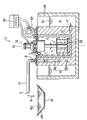
Fig. 1 (a) is the vertical profile schematic diagram of the molten non-ferrous metal pump of the first embodiment of the present invention, the vertical profile schematic diagram that (b) is hydrostatic column part.
The molten non-ferrous metal pump plane that Fig. 2 (a) is Fig. 1, profile, (c) figure that (b) is lid are that 2 (a) remove the plane after lid.
The plane of the floor map that Fig. 3 (a) is magnetic field device, the another kind of embodiment that (b) is magnetic field device.
Fig. 4 is the vertical profile schematic diagram of the second embodiment of molten non-ferrous metal pump.
Fig. 5 is the melting furnace system vertical profile schematic diagram that Fig. 1 is used molten non-ferrous metal pump.
Fig. 6 is the vertical profile schematic diagram of other embodiments of presentation graphs 5 melting furnace systems.
The specific embodiment:
Fig. 1 (a) is the vertical section schematic diagram of the first embodiment of the present invention, and Fig. 2 (a) is its plane schematic diagram.From Fig. 1 (a), can find out, molten non-ferrous metal pump 1 in the first embodiment of the present invention shown in 1 (a), Fig. 2 (b), its structure is, rely on electromagnetic force that molten non-ferrous metal (liquation of the conductor (electric conductor) of the alloy of at least 2 kinds of materials or Mg alloy etc. in Al, Cu, Zn or these non-ferrous metals) is sucked from lower end entrance, from liquid outlet 3, discharge.
From Fig. 1 (a), can find out, concrete structure is, the opening-like state of above-mentioned lower end entrance 2 be positioned at refractory material (heat proof material), make, near the cylindrical side wall bottom as the hydrostatic column 5 of urceolus.
In the upper edge portion of above-mentioned hydrostatic column 5, the opening-like state of upper end open 6 communicates with above-mentioned liquid outlet 3.Direct representation is out in following plane Fig. 2 (c) that removes lid 12 for this upper end open 6.Lower end entrance 2 communicates by molten non-ferrous metal passage 8 in the cylindrical side wall of above-mentioned hydrostatic column 5 with upper end open 6.This molten non-ferrous metal passage 8 consists of 2 passages that are connected, that is: from only show Fig. 1 (b) of hydrostatic column 5, can find out, molten non-ferrous metal passage 8 consists of the helical duct 8a of container body 11 the latter halfs that are interconnected and longitudinal rising passway 8b of the first half.Molten non-ferrous metal M is inhaled into lower end entrance 2 under the driving of following electromagnetic force, is spiraled and is risen to rising passway 8b, then rise by this rising passway 8 by helical duct 8, from above-mentioned liquid outlet 3, discharges.
In addition, cross section shows that above-mentioned molten non-ferrous metal passage 8 is for circular, and certainly, the shape in cross section can be not only circular, can also be ellipse, rectangle, polygonal or other shapes.
From Fig. 1 (a), Fig. 2 (c), can find out, in the inner side of above-mentioned hydrostatic column 5, as inner core, container inside the same cylindrical that 4 heat-insulating materials make is housed, form the dual structure container body 11 that so-called refractory material is made.The inside 11 of this container body is so-called inner space.
From Fig. 1 (a), can find out, these container body 11 upper openings are provided with lid 12.The profile of this lid 12 is as shown in Fig. 2 (b).From Fig. 2 (b), can find out on this lid 12, have liquation hole 12a, wind pushing hole 12b, vent 12c, output shaft hole 12d.Above-mentioned inner space is by wind pushing hole 12b, vent 12c and exterior.
From Fig. 1 (a), Fig. 2 (a), can find out the exhaust duct 14 that is provided with sealing, communicates in the 12c of the said exhaust hole of above-mentioned lid 12.The upper end of this exhaust duct 14 is exhaust outlet 14a.
From Fig. 1 (a), Fig. 2 (a), can find out, the drain pipe 15 close to L-type is housed on this lid 12.The outlet end of this drain pipe 15 is above-mentioned liquid outlet 3.The lower end of this drain pipe 15 is sealing state with the above-mentioned liquation hole 12a of above-mentioned lid 12 and communicates.And this liquation hole 12a communicates with the above-mentioned passage 8b of above-mentioned hydrostatic column 5.Like this, above-mentioned rising passway 8b communicates with above-mentioned liquid outlet 3 by above-mentioned drain pipe 5.The above-mentioned lower end entrance 2 that is above-mentioned hydrostatic column 5 communicates with above-mentioned liquid outlet 3 by helical duct 8a, rising passway 8b and drain pipe 15.
From Fig. 1 (a), figure (b), can find out, on above-mentioned lid 12, by pedestal 17, the drive motors (drive unit) 18 with the vertical output shaft 18a along axis AL is housed.And, below this lid 12, be provided with the rotatable shaft 19 being supported by bearing 13.Above-mentioned output shaft 18a, by the output shaft hole 12d of above-mentioned lid 12, relies on shaft joint (not shown) to be connected (linking together) with axle 19, realizes the transmission of revolving force.Be that above-mentioned output shaft 18a is connected with above-mentioned axle 19, make the rotation of output shaft 18a can be sent to axle 19.
The end portion of this axle 19 is equipped with magnetic field device 20.Be that magnetic field device 20 relies on lid 12 to overhang in inner side container 4.The magnetic line of force ML of this magnetic field device 20 almost penetrates in horizontal direction, through again returning in horizontal direction after the molten non-ferrous metal in above-mentioned helical duct 8a, forms magnetic field intensity.Rely on this magnetic field intensity to start the rear magnetic field device 20 of above-mentioned drive motors 18 and start rotation, magnetic line of force ML is thereupon in rotary moving in the molten non-ferrous metal M through in helical duct 8a.Molten non-ferrous metal M relies on the electromagnetic force now producing to flow and rise to above-mentioned passage 8b along this helical duct 8a, more further rises to above-mentioned drain pipe 15, from above-mentioned liquid outlet 3, discharges.
As mentioned above, if the magnetic line of force ML that magnetic field device 20 penetrates is the magnetic line of force through the molten non-ferrous metal M in helical duct 8a, so specifically can adopt various structures.
For example, can adopt the structure shown in Fig. 3 (a) or Fig. 3 (b).
Structure shown in Fig. 3 (a) is to use the structure of 4 permanent magnets 25 of configuration around above-mentioned axis AL.Between upper plate 22 and lower plate 23, accompany multiple permanent magnets 25,4 column permanent magnets 25 for example arranging in virtual circumference.Each permanent magnet 25 is magnetized, and makes above-mentioned axis AL inner circumferential side and outer circumferential side around become magnetic pole.And along the circumferential direction adjacent 2 permanent magnets 25,25 are magnetized, make its outer circumferential side mutually different from the magnetic pole of inner circumferential side.Therefore, from Fig. 3 (a), can find out, the magnetic line of force ML that certain permanent magnet 25 penetrates can enter another adjacent permanent magnet 25, and as mentioned above, these magnetic lines of force ML can be through the molten non-ferrous metal M in above-mentioned helical duct 8a.Like this, when magnetic line of force ML is in rotary moving, molten non-ferrous metal M rises in helical duct 8a inside turn.
Structure shown in Fig. 3 (b) is to use the structure of 1 permanent magnet.As shown in Fig. 3 (b), also can be using magnetic field device 20 as a cylindrical permanent magnet 27.On this permanent magnet 27, clip the horizontal relative two side portions of above-mentioned axis AL and be geomagnetic into separately different magnetic poles.The magnetic line of force ML penetrating from this permanent magnet 27 also acts on the molten non-ferrous metal M in helical duct 8a.Molten non-ferrous metal M relies on this magnetic line of force ML to rise in helical duct 8a inside turn.
While using the magnetic field device 20 of this Fig. 3 (b), also can take someway magnetic field device 20 to be arranged on axle 19, by axle 19, rotarily actuate this magnetic field device 20.
And, from Fig. 1 (a), Fig. 2 (a), can find out, on above-mentioned lid 12, air blast 29 is housed.The ajutage 29a of this air blast 29 is sealing state and communicates with the above-mentioned wind pushing hole 12b of lid 12.Like this, when air blast 29 is blown, as shown in arrow in Fig. 1 (a), air carries out cooling to each several part by inner space, and discharge from said exhaust mouth 14a.
In addition, in Fig. 2,30 is power supply control panel, at this, above-mentioned drive motors 18 and above-mentioned air blast 29 is carried out to Power supply and control.
The operation of the molten non-ferrous metal pump 1 to said structure describes.
This molten non-ferrous metal pump 1, under the state being immersed in molten non-ferrous metal M, is to be at least immersed under the state in molten non-ferrous metal M and to use at above-mentioned lower end entrance 2.And air blast 29 should keep the state of real-time working, to guarantee fluid under cooling state.
The operation of this pump is described as follows:
Conventionally, magnetic field (magnetic line of force ML) acts on molten non-ferrous metal M, if mobile this magnetic field can produce vortex flow in molten non-ferrous metal M.So,, in molten non-ferrous metal, electromagnetic force can produce by the moving direction in magnetic field.Therefore, in the present invention, at an angle, the electromagnetic force that acts on molten non-ferrous metal is divided into vertical component and horizontal component for the installation of the passage (helical duct 8a) of molten non-ferrous metal and the all-moving surface (electromagnetic force face) in magnetic field.Molten non-ferrous metal in helical duct 8a relies on this vertical component to be pushed to top, and like this, the molten non-ferrous metal in helical duct 8a, when magnetic field device 20 rotates, is screw and is moved upward.Soon, above-mentioned molten non-ferrous metal moves to rising passway 8b from helical duct 8a.Molten non-ferrous metal in rising passway 8b, flows out from liquid outlet 3 to being pushed into drain pipe 15 from rear.Now, along with the movement of molten non-ferrous metal in helical duct 8a, lower end entrance 2 sucks new molten non-ferrous metal simultaneously, is delivered in helical duct 8a.Like this, molten non-ferrous metal continuously sucks from lower end entrance 2, from liquid outlet 3, flows out.
At this, the translational speed of molten non-ferrous metal M, highly (lift) be directly proportional to the translational speed (rotary speed) in magnetic field.Therefore, if use the revolution of current transformer controlling magnetic field device 20, capable of regulating liquid outlet quantity, lift and fluid speed.In addition, can be by adding long cylindrical vessel 5, i.e. the mode of helical duct 8a, sets arbitrarily lift.
Fig. 4 is the vertical section schematic diagram as the molten non-ferrous metal pump 1A of the second embodiment of molten non-ferrous metal pump 1 variation of the first embodiment of Fig. 1 (a).The difference of this second embodiment and the first embodiment is the helical duct 8Aa in the molten non-ferrous metal passage 8A of formation hydrostatic column 5A to lengthen, rising passway 8Ab is shortened, and correspondingly lengthen magnetic field device 20A according to helical duct 8Aa.Be that helical duct 8Aa almost equates with the whole height of container body 11A.
Like this, owing to having lengthened magnetic field device 20A, can further improve the driving force of the molten non-ferrous metal that relies on magnetic field device 20A driving.
In addition, although we the hydrostatic column 5A of Fig. 4 is used as hydrostatic column, but should prepare several in magnetic field device the different magnetic field device of permanent magnet length, according to different situations exchanges, use.Sometimes using the magnetic field device 20 of Fig. 1 (a) as magnetic field device, use, sometimes use the magnetic field device 20A of Fig. 4, or use the magnetic field device of the permanent magnet of other different lengths, can change like this driving force of molten non-ferrous metal M.
Fig. 5 melting furnace system of the present invention of molten non-ferrous metal pump 1 that has been the use shown in Fig. 1 (a).
As can be seen from Figure 5, molten non-ferrous metal pump 1 is arranged in holding furnace (or melting furnace) 40, and direct impregnation is in molten non-ferrous metal M.Now, at least above-mentioned lower end entrance 2 should be immersed in molten non-ferrous metal M.
Owing to being immersed in the molten non-ferrous metal M of high temperature, air blast 29 should often keep ON state.
As explanation just now, open now drive motors 18, the molten non-ferrous metal M of electromagnetic force in helical duct 8a, molten non-ferrous metal M rises in helical duct 8a inside turn, through rising passway 8b and drain pipe 15, from liquid outlet 3, flows out.Now, because molten non-ferrous metal M is continuously sucked from lower end entrance 2, therefore, molten non-ferrous metal M continuously enters liquid reserve tank from liquid outlet 3.
Fig. 6 is the vertical section schematic diagram of the melting furnace system variation of Fig. 5.
The 1A of melting furnace system shown in Fig. 6 is, once magnetic field device 20 applies power, liquid outlet 3A starts after fluid, even if cut off this magnetic field device 20, stops power supply, and according to siphon principle, above-mentioned liquation will continuously outflow system.
The difference of the system of Fig. 6 and the melting furnace system of Fig. 51 is specific as follows:
Folding under drain pipe 15A is extended, the liquid outlet 3A on top is inserted in the liquation M2 in liquid reserve tank 42.
In this state, rely on magnetic field device 20 that liquation M is discharged from liquid outlet 3A.Even if stop afterwards magnetic field device 20, according to the above-mentioned liquation of siphon principle, will continuously outflow.
As system architecture, drain pipe 15A need to have suitable length, to make the position of liquid outlet 3A at least can be lower than the liquid level Ms of holding furnace 40 inner melt M.
In addition, in the lateral part of the extreme higher position of drain pipe 15A, blast pipe 50 is installed.As below on this question explanation like that, this be for operation the most at the beginning liquation M can be smoothly through drain pipe 15A rising.
Be described as follows:
The concrete operation of the melting furnace system 1A of said structure is as follows:
The switch of opening power dish 30, liquation, flows in the liquation M2 in liquid reserve tank 42 from liquid outlet 3A to drain pipe 15A by molten non-ferrous metal passage 8 (helical duct 8a and above-mentioned passage 8b).
Before being entry into service, in drain pipe 15A, be full of air.This air can hinder liquation M smoothly by rising in molten non-ferrous metal passage 8 and drain pipe 15A.Therefore, before bringing into operation, first open the valve 50 of drain pipe 15A, discharge the air of the inside, then bring into operation in this state.Like this, liquation M spirals and rises to drain pipe 15A along the molten non-ferrous metal passage 8 (8a, 8b) of hydrostatic column 5, starts to rise along the cardinal extremity part of drain pipe 15A.By this rising, the air in drain pipe 15 is extruded from valve 50.Liquation M arrives the position late gate 50 of valve 50 and closes, and afterwards, liquation M, not having under the impact of air in drain pipe 15A, flows in the liquation M2 in liquid reserve tank 42 by drain pipe 15A smoothly.Then the switch of powered-down dish 30 correspondences.Even if closed switch, afterwards, owing to there is height difference H between the liquation M2 liquid level M2s in liquation M liquid level Ms and liquid reserve tank in holding furnace, according to siphon principle, the liquation M in holding furnace 40 will continuously flow in liquid reserve tank 42.That is to say even without apply the power of thinking from outside, also fluid continuously.
Claims (20)
1. a molten non-ferrous metal pump, is characterized in that:
Have by inner space with for be located at lower end entrance on each sidewall and the container body of upper end open molten non-ferrous metal passage that be connected, that form in described sidewall at outside opening, described molten non-ferrous metal passage comprises a helical duct and a coupled longitudinal rising passway, described lower end entrance is connected with one end of described helical duct, the other end of described helical duct is connected with one end of described longitudinal rising passway, and the other end of described longitudinal rising passway is connected with described upper end open;
Have be located in described inner space, can around longitudinal axis rotation for driving the magnetic field device of the molten non-ferrous metal in helical duct, during described magnetic field device rotation, its magnetic field intensity can make the magnetic line of force move under the state through molten non-ferrous metal in above-mentioned helical duct, thereby make the liquation spiral in helical duct move up and vertically towards the direction of upper end open, upwards promote the liquation in described longitudinal rising passway, and
There is the drive unit that rotarilys actuate described magnetic field device.
2. molten non-ferrous metal pump according to claim 1, is characterized in that: the longitudinal rising passway forming in the described sidewall of the upper end of described helical duct by described container body communicates with described upper end open.
3. molten non-ferrous metal pump according to claim 1, is characterized in that: described magnetic field device is comprised of permanent magnet.
4. molten non-ferrous metal pump according to claim 3, it is characterized in that: described magnetic field device possesses multiple permanent magnets of installing around described axis, described each permanent magnet is magnetized, make inner side and outside become magnetic pole with respect to described axis, and, multiple permanent magnets are installed along described axis outer circumferential side and inner circumferential side around, make variant magnetic pole alternative arrangement.
5. molten non-ferrous metal pump according to claim 3, is characterized in that: described magnetic field device has a permanent magnet, and described permanent magnet is magnetized, and making to accompany the horizontal relative two side portions of described axis becomes magnetic pole.
6. molten non-ferrous metal pump according to claim 1, is characterized in that: have the lid that stops up the described inner space in described container body, described magnetic field device in vertical state and rotatable state is relative with described lid installs.
7. molten non-ferrous metal pump according to claim 1, is characterized in that: described drive unit is housed on described lid.
8. molten non-ferrous metal pump according to claim 1, is characterized in that: the output shaft of described drive unit is connected by shaft joint with the axle of the described magnetic field device of rotatable support, realizes the transmission of revolving force.
9. molten non-ferrous metal pump according to claim 1, it is characterized in that: described lid has the wind pushing hole and the vent that make described inner space and exterior, cooling-air is sent into described inner space from described wind pushing hole, and discharges to outside from described vent.
10. molten non-ferrous metal pump according to claim 9, is characterized in that: the ajutage of air blast communicates with described wind pushing hole, and exhaust duct communicates with described vent.
11. molten non-ferrous metal pumps according to claim 1, it is characterized in that: described container body forms dual structure container by the hydrostatic column as urceolus with as the inner side container of inner core, forms described molten non-ferrous metal passage on the sidewall of described hydrostatic column.
12. molten non-ferrous metal pumps according to claim 2, is characterized in that: the latter half of described container body height is provided with described helical duct, the first half is provided with described rising passway.
13. molten non-ferrous metal pumps according to claim 1, is characterized in that: described helical duct almost equates with the whole height of described container body.
14. molten non-ferrous metal pumps according to claim 1, is characterized in that: on described lid, have fluid hole, and on described lid, the drain pipe communicating with described fluid hole is housed, described fluid hole is sealing state with described molten non-ferrous metal passage and communicates.
15. molten non-ferrous metal pumps according to claim 1, is characterized in that: have a described container body and launch multiple magnetic field devices of different magnetic field intensity, with respect to described container body, any one that change described multiple magnetic field devices can be used.
16. molten non-ferrous metal pumps according to claim 1, is characterized in that: the cross section of described molten non-ferrous metal passage is circular, ellipse, rectangle or polygonal.
17. molten non-ferrous metal pumps according to claim 1, is characterized in that: drain pipe is connected state and is connected with described upper end open, and the end of described drain pipe is provided with the liquid outlet that described molten non-ferrous metal outwards flows out.
18. molten non-ferrous metal pumps according to claim 17, is characterized in that: described liquid outlet is located at higher than described lower end entrance part.
19. 1 kinds of melting furnace systems, it is characterized in that: there is molten non-ferrous metal pump according to claim 1 and the stove of memory space with storage molten non-ferrous metal, can impregnated under the state in the non-ferrous metal being stored in this memory space at described lower end entrance, described molten non-ferrous metal is stored in the described memory space in described stove.
20. 1 kinds of melting furnace systems, it is characterized in that: there is molten non-ferrous metal pump according to claim 17 and the stove of memory space with storage molten non-ferrous metal, can impregnated under the state in the non-ferrous metal being stored in this memory space at described lower end entrance, described molten non-ferrous metal is stored in the described memory space in described stove, and the position of the described liquid outlet on described drain pipe is lower than the liquation liquid level of storing in described stove.
Applications Claiming Priority (4)
| Application Number | Priority Date | Filing Date | Title |
|---|---|---|---|
| JP2010088793 | 2010-04-07 | ||
| JP2010-088793 | 2010-04-07 | ||
| JP2010152816A JP5546974B2 (en) | 2010-04-07 | 2010-07-05 | Non-ferrous metal melt pump and melting furnace system using the same |
| JP2010-152816 | 2010-07-05 |
Publications (2)
| Publication Number | Publication Date |
|---|---|
| CN102213552A CN102213552A (en) | 2011-10-12 |
| CN102213552B true CN102213552B (en) | 2014-05-07 |
Family
ID=44168486
Family Applications (2)
| Application Number | Title | Priority Date | Filing Date |
|---|---|---|---|
| CN201110063647.5A Expired - Fee Related CN102213552B (en) | 2010-04-07 | 2011-03-15 | Non-ferrous metal melt pump and melting furnace system using same |
| CN2011200678878U Expired - Fee Related CN202157970U (en) | 2010-04-07 | 2011-03-15 | Non-ferrous metal melting pump and melting furnace system using the metal pump |
Family Applications After (1)
| Application Number | Title | Priority Date | Filing Date |
|---|---|---|---|
| CN2011200678878U Expired - Fee Related CN202157970U (en) | 2010-04-07 | 2011-03-15 | Non-ferrous metal melting pump and melting furnace system using the metal pump |
Country Status (7)
| Country | Link |
|---|---|
| US (1) | US8585962B2 (en) |
| EP (1) | EP2375206B1 (en) |
| JP (1) | JP5546974B2 (en) |
| KR (1) | KR101242063B1 (en) |
| CN (2) | CN102213552B (en) |
| AU (1) | AU2011201019B2 (en) |
| CA (1) | CA2733470C (en) |
Families Citing this family (24)
| Publication number | Priority date | Publication date | Assignee | Title |
|---|---|---|---|---|
| US8267669B2 (en) * | 2008-05-19 | 2012-09-18 | Hazelett Strip-Casting Corporation | Magnetic induction pump |
| JP5546974B2 (en) * | 2010-04-07 | 2014-07-09 | 株式会社ヂーマグ | Non-ferrous metal melt pump and melting furnace system using the same |
| PL220603B1 (en) | 2012-03-31 | 2015-11-30 | Biopal Spółka Z Ograniczoną Odpowiedzialnością | Liquid metal pump for the chemical reactor heating circuit |
| JP5819270B2 (en) * | 2012-08-08 | 2015-11-18 | 高橋 謙三 | Permanent magnet type cylindrical molten metal stirrer and melting furnace with permanent magnet pump |
| JP5795296B2 (en) * | 2012-09-27 | 2015-10-14 | 高橋 謙三 | Vortex chamber body for metal melting furnace and metal melting furnace using the same |
| CN103115498A (en) * | 2012-11-11 | 2013-05-22 | 昆山市大金机械设备厂 | Electromagnetic transmission device of metal melting furnace |
| HUE033155T2 (en) | 2013-03-11 | 2017-11-28 | Novelis Inc | Magnetic pump installation |
| JP5813693B2 (en) * | 2013-04-23 | 2015-11-17 | 高橋 謙三 | Molten metal circulation drive device and main bus having the same |
| GB2515475B (en) | 2013-06-21 | 2016-08-31 | Emp Tech Ltd | Metallurgical apparatus |
| WO2015179680A2 (en) | 2014-05-21 | 2015-11-26 | Novelis Inc. | Mixing eductor nozzle and flow control device |
| PL3086069T3 (en) * | 2015-04-23 | 2019-11-29 | Digimet 2013 Sl | FURNACE FOR MELTING AND TREATMENT OF METAL AND METAL WASTE AND THEIR METHOD |
| WO2016194910A1 (en) * | 2015-06-03 | 2016-12-08 | 謙三 高橋 | Conductive metal melting furnace, conductive metal melting furnace system equipped with same, and conductive metal melting method |
| JP6039010B1 (en) * | 2015-04-23 | 2016-12-07 | 高橋 謙三 | Conductive metal melting furnace, conductive metal melting furnace system including the same, and conductive metal melting method |
| DE102015220514A1 (en) * | 2015-10-21 | 2017-04-27 | Ersa Gmbh | solder pump |
| JP6042519B1 (en) * | 2015-11-05 | 2016-12-14 | 高橋 謙三 | Molten metal transfer pump and molten metal transfer system |
| CN106563794A (en) * | 2016-04-05 | 2017-04-19 | 邓君 | A feeding device for casting tapered rollers |
| CN107394987B (en) * | 2017-09-14 | 2019-09-20 | 东莞市神州视觉科技有限公司 | Electric rotating magnetic pumping |
| JP2020065318A (en) * | 2018-10-15 | 2020-04-23 | 株式会社宮本工業所 | Electrically-conductive liquid pump |
| JP7515173B2 (en) * | 2020-12-21 | 2024-07-12 | 株式会社ヂーマグ | Molten Metal Pump |
| JP7637403B2 (en) * | 2020-12-21 | 2025-02-28 | 株式会社ヂーマグ | Molten Metal Pump |
| CN115216636A (en) * | 2022-08-17 | 2022-10-21 | 维苏威高级陶瓷(中国)有限公司 | Gear-driven non-ferrous metal liquid refining device |
| CN118017795B (en) * | 2024-04-08 | 2024-06-25 | 浙江大学 | Induction electromagnetic pump |
| FR3166962A1 (en) | 2024-09-30 | 2026-04-03 | Lethiguel | Installation of a furnace for liquid metal, with electric heating and improved stirring. |
| WO2026069257A1 (en) | 2024-09-30 | 2026-04-02 | Lethiguel | Furnace installation for liquid metal, with electric heating and improved stirring |
Citations (4)
| Publication number | Priority date | Publication date | Assignee | Title |
|---|---|---|---|---|
| US3196795A (en) * | 1963-01-02 | 1965-07-27 | North American Aviation Inc | Electromagnetic pump system |
| GB1100474A (en) * | 1965-04-29 | 1968-01-24 | North American Aviation Inc | Electromagnetic pump |
| CN1793765A (en) * | 2004-12-22 | 2006-06-28 | 高桥谦三 | Stirring device and method, and melting furnace with stirring device using the stirring device |
| CN202157970U (en) * | 2010-04-07 | 2012-03-07 | Zmag株式会社 | Non-ferrous metal melting pump and melting furnace system using the metal pump |
Family Cites Families (8)
| Publication number | Priority date | Publication date | Assignee | Title |
|---|---|---|---|---|
| JPS6255486A (en) * | 1985-09-02 | 1987-03-11 | Terumasa Tsuru | Electromagnetic pump |
| JPH05161340A (en) * | 1991-11-21 | 1993-06-25 | Ishikawajima Harima Heavy Ind Co Ltd | Molten metal circulating pump |
| JP3824365B2 (en) * | 1996-12-27 | 2006-09-20 | 高橋 謙三 | Molten metal transfer pump |
| JP2001251843A (en) * | 2000-03-01 | 2001-09-14 | Tamura Seisakusho Co Ltd | Pumping apparatus |
| KR101213559B1 (en) * | 2004-12-22 | 2012-12-18 | 겐조 다카하시 | Apparatus and method for agitating, and melting furnace attached to agitation apparatus using agitation apparatus |
| JP2007074837A (en) * | 2005-09-08 | 2007-03-22 | Sukegawa Electric Co Ltd | Inductive electromagnetic pump for liquid metal |
| JP4995234B2 (en) * | 2008-12-26 | 2012-08-08 | 株式会社ヂーマグ | Non-ferrous metal melt pump and non-ferrous metal melting furnace using the same |
| JP5496647B2 (en) * | 2009-12-28 | 2014-05-21 | 高橋 謙三 | Non-ferrous metal melt pump |
-
2010
- 2010-07-05 JP JP2010152816A patent/JP5546974B2/en active Active
-
2011
- 2011-02-25 KR KR1020110017335A patent/KR101242063B1/en not_active Expired - Fee Related
- 2011-03-08 AU AU2011201019A patent/AU2011201019B2/en active Active
- 2011-03-08 CA CA2733470A patent/CA2733470C/en active Active
- 2011-03-08 US US13/043,246 patent/US8585962B2/en not_active Expired - Fee Related
- 2011-03-10 EP EP11157760.7A patent/EP2375206B1/en active Active
- 2011-03-15 CN CN201110063647.5A patent/CN102213552B/en not_active Expired - Fee Related
- 2011-03-15 CN CN2011200678878U patent/CN202157970U/en not_active Expired - Fee Related
Patent Citations (4)
| Publication number | Priority date | Publication date | Assignee | Title |
|---|---|---|---|---|
| US3196795A (en) * | 1963-01-02 | 1965-07-27 | North American Aviation Inc | Electromagnetic pump system |
| GB1100474A (en) * | 1965-04-29 | 1968-01-24 | North American Aviation Inc | Electromagnetic pump |
| CN1793765A (en) * | 2004-12-22 | 2006-06-28 | 高桥谦三 | Stirring device and method, and melting furnace with stirring device using the stirring device |
| CN202157970U (en) * | 2010-04-07 | 2012-03-07 | Zmag株式会社 | Non-ferrous metal melting pump and melting furnace system using the metal pump |
Also Published As
| Publication number | Publication date |
|---|---|
| AU2011201019B2 (en) | 2013-10-10 |
| KR20110112769A (en) | 2011-10-13 |
| US8585962B2 (en) | 2013-11-19 |
| CA2733470C (en) | 2014-01-14 |
| JP5546974B2 (en) | 2014-07-09 |
| CN202157970U (en) | 2012-03-07 |
| AU2011201019A1 (en) | 2011-10-27 |
| CN102213552A (en) | 2011-10-12 |
| KR101242063B1 (en) | 2013-03-11 |
| CA2733470A1 (en) | 2011-10-07 |
| JP2011230187A (en) | 2011-11-17 |
| US20110248432A1 (en) | 2011-10-13 |
| EP2375206A1 (en) | 2011-10-12 |
| EP2375206B1 (en) | 2017-05-03 |
Similar Documents
| Publication | Publication Date | Title |
|---|---|---|
| CN102213552B (en) | Non-ferrous metal melt pump and melting furnace system using same | |
| CN105896669A (en) | Charging pile for electric vehicle | |
| CN105499523A (en) | Pouring device for metal smelting and pouring method | |
| JP2014213333A5 (en) | ||
| CN102322203A (en) | Door window with accumulated water sensing device and automatic air supply and exhaust functions | |
| CN102935499A (en) | Soup cup matched with soup feeding machine | |
| CN106521560B (en) | A kind of liquid rare earth metal discharging device | |
| CN208181444U (en) | Unmanned plane integrates make-up system | |
| CN208037873U (en) | Crane applied to data center | |
| CN108496939B (en) | Automatic medicine system of irritating of plant protection unmanned aerial vehicle | |
| CN203440881U (en) | Flushing panel structure of concealed-type water tank and concealed-type water tank | |
| CN107860143A (en) | A kind of scalable solar water heater | |
| CN217210304U (en) | Furnace liner protection device of medium frequency induction furnace | |
| CN211174873U (en) | Full-automatic emulsion case of automatic feeding ratio for coal mine | |
| CN210220639U (en) | Fixed-point quantitative intermediate frequency induction smelting tilting casting furnace | |
| CN203514398U (en) | Installation device for tubular pump | |
| CN101642807B (en) | Molten metal casting device and smelter | |
| CN209228157U (en) | Three-dimensional garage control system | |
| CN112964060A (en) | Low-energy-consumption vacuum induction master alloy smelting furnace | |
| CN207881469U (en) | Tunnel type aluminium smelting furnace group with illumination monitoring equipment | |
| CN201021668Y (en) | Fully automatic driving pump | |
| CN204584243U (en) | NdFeB rear-earth material apparatus for pouring hydraulic system | |
| CN101075776B (en) | Flow-guiding pipe for DC electromagnetic pump | |
| CN203437632U (en) | Molten metal continuous quantification casting device | |
| CN108165692A (en) | A kind of blast furnace residual iron placing scheduling process and device |
Legal Events
| Date | Code | Title | Description |
|---|---|---|---|
| C06 | Publication | ||
| PB01 | Publication | ||
| C10 | Entry into substantive examination | ||
| SE01 | Entry into force of request for substantive examination | ||
| C14 | Grant of patent or utility model | ||
| GR01 | Patent grant | ||
| CF01 | Termination of patent right due to non-payment of annual fee | ||
| CF01 | Termination of patent right due to non-payment of annual fee |
Granted publication date: 20140507 |