CN102158366A - Onboard communication chain data statistic device - Google Patents

Onboard communication chain data statistic device Download PDF

Info

Publication number
CN102158366A
CN102158366A CN2010105689169A CN201010568916A CN102158366A CN 102158366 A CN102158366 A CN 102158366A CN 2010105689169 A CN2010105689169 A CN 2010105689169A CN 201010568916 A CN201010568916 A CN 201010568916A CN 102158366 A CN102158366 A CN 102158366A
Authority
CN
China
Prior art keywords
port
unit
serial
protocol
data
Prior art date
Legal status (The legal status is an assumption and is not a legal conclusion. Google has not performed a legal analysis and makes no representation as to the accuracy of the status listed.)
Granted
Application number
CN2010105689169A
Other languages
Chinese (zh)
Other versions
CN102158366B (en
Inventor
张琳
张航
Current Assignee (The listed assignees may be inaccurate. Google has not performed a legal analysis and makes no representation or warranty as to the accuracy of the list.)
CETC 54 Research Institute
Original Assignee
CETC 54 Research Institute
Priority date (The priority date is an assumption and is not a legal conclusion. Google has not performed a legal analysis and makes no representation as to the accuracy of the date listed.)
Filing date
Publication date
Application filed by CETC 54 Research Institute filed Critical CETC 54 Research Institute
Priority to CN 201010568916 priority Critical patent/CN102158366B/en
Publication of CN102158366A publication Critical patent/CN102158366A/en
Application granted granted Critical
Publication of CN102158366B publication Critical patent/CN102158366B/en
Expired - Fee Related legal-status Critical Current
Anticipated expiration legal-status Critical

Links

Images

Landscapes

  • Mobile Radio Communication Systems (AREA)

Abstract

本发明公开了一种机载通信链路数据统计装置,它涉及通信领域中可用于机载设备的低频装置。它由调制解调器、复分接器、监控器、电源等部件组成。本发明支持设备通信状态的信息上报,包括两路分集信号频谱、两路分集信号SNR估计值、两路分集信号接收电平,均衡后眼图,传输速率,数据误码率和两端通信设备所处GPS方位,通信距离等。本发明具有能够实时对通信链路的状态进行检测和监控的特点,并且依靠设备自身的电路和程序,不需额外增加电路。特别适用于地空-莱斯信道下,对通信链路状态进行实时监控,和对各工作模块取得的测试数据进行记录,并进行后续分析的机载通信设备。

Figure 201010568916

The invention discloses an airborne communication link data statistics device, which relates to a low-frequency device that can be used for airborne equipment in the communication field. It consists of a modem, a multiplexer, a monitor, a power supply and other components. The present invention supports information reporting of equipment communication status, including two-way diversity signal spectrum, two-way diversity signal SNR estimated value, two-way diversity signal receiving level, eye diagram after equalization, transmission rate, data bit error rate and communication equipment at both ends GPS location, communication distance, etc. The invention has the characteristics of being able to detect and monitor the state of the communication link in real time, and relies on the circuit and program of the device itself without adding additional circuits. It is especially suitable for airborne communication equipment for real-time monitoring of communication link status, recording of test data obtained by each working module, and subsequent analysis under the ground-air-Rice channel.

Figure 201010568916

Description

机载通信链路数据统计装置Airborne communication link data statistics device

技术领域technical field

本发明涉及通信领域中一种通信链路数据统计装置,它依靠自身的电路和程序,对通信链路的状态进行监测和记录,特别适用于轻型化设计的机载通信设备,对通信链路状态进行实时监控,和对各工作模块取得的测试数据进行记录。The invention relates to a communication link data statistical device in the field of communication, which monitors and records the state of the communication link by relying on its own circuit and program, and is especially suitable for light-weight design of airborne communication equipment. The status is monitored in real time, and the test data obtained by each working module is recorded.

背景技术Background technique

地空通信为典型的高动态、低仰角、低莱斯因子信道,飞机高速运动引起信道时变、码间干扰、误码率恶化、多普勒频移等。传统的机载通信设备对信道通信状况的监控需要借助各种测试仪器,例如:频谱仪、示波器、误码仪等。而追求轻型化的机载通信发展趋势,使飞机携带各种仪器是不切合实际的。Ground-to-air communication is a typical channel with high dynamics, low elevation angle, and low Rice factor. The high-speed movement of aircraft causes channel time variation, intersymbol interference, bit error rate deterioration, and Doppler frequency shift. The monitoring of channel communication status by traditional airborne communication equipment requires the help of various test instruments, such as spectrum analyzers, oscilloscopes, and bit error meters. However, the pursuit of lightweight airborne communication development trend makes it impractical for aircraft to carry various instruments.

发明内容Contents of the invention

本发明的目的在于避免上述背景技术中的不足之处而提供一种适用于机载通信的,实时监控通信链路状态和各工作单元状态的数据统计技术。本发明利用采集到的各工作模块的测试数据,通过特殊协议,以串口方式发送到PC,通过监视软件实时地显示并记录链路状态和控制信息,包括:两路分集信号频谱、两路分集信号SNR估计值、两路分集信号接收电平,均衡后眼图,传输速率,误码率和两端通信设备所处GPS方位,通信距离等;也可将以上信息将记录在数据库中,供后续研究。而且此项技术还具有利用自身的电路和程序,不需额外增加电路的特点。The purpose of the present invention is to avoid the disadvantages of the above-mentioned background technology and provide a data statistics technology suitable for airborne communication, real-time monitoring of communication link status and each working unit status. The present invention uses the collected test data of each working module to send to the PC through a serial port through a special protocol, and displays and records the link status and control information in real time through the monitoring software, including: two-way diversity signal spectrum, two-way diversity Signal SNR estimate, two-way diversity signal receiving level, eye diagram after equalization, transmission rate, bit error rate, GPS position of communication equipment at both ends, communication distance, etc.; the above information can also be recorded in the database for follow up research. Moreover, this technology also has the advantage of using its own circuit and program without adding additional circuits.

本发明的目的是这样实现的:The purpose of the present invention is achieved like this:

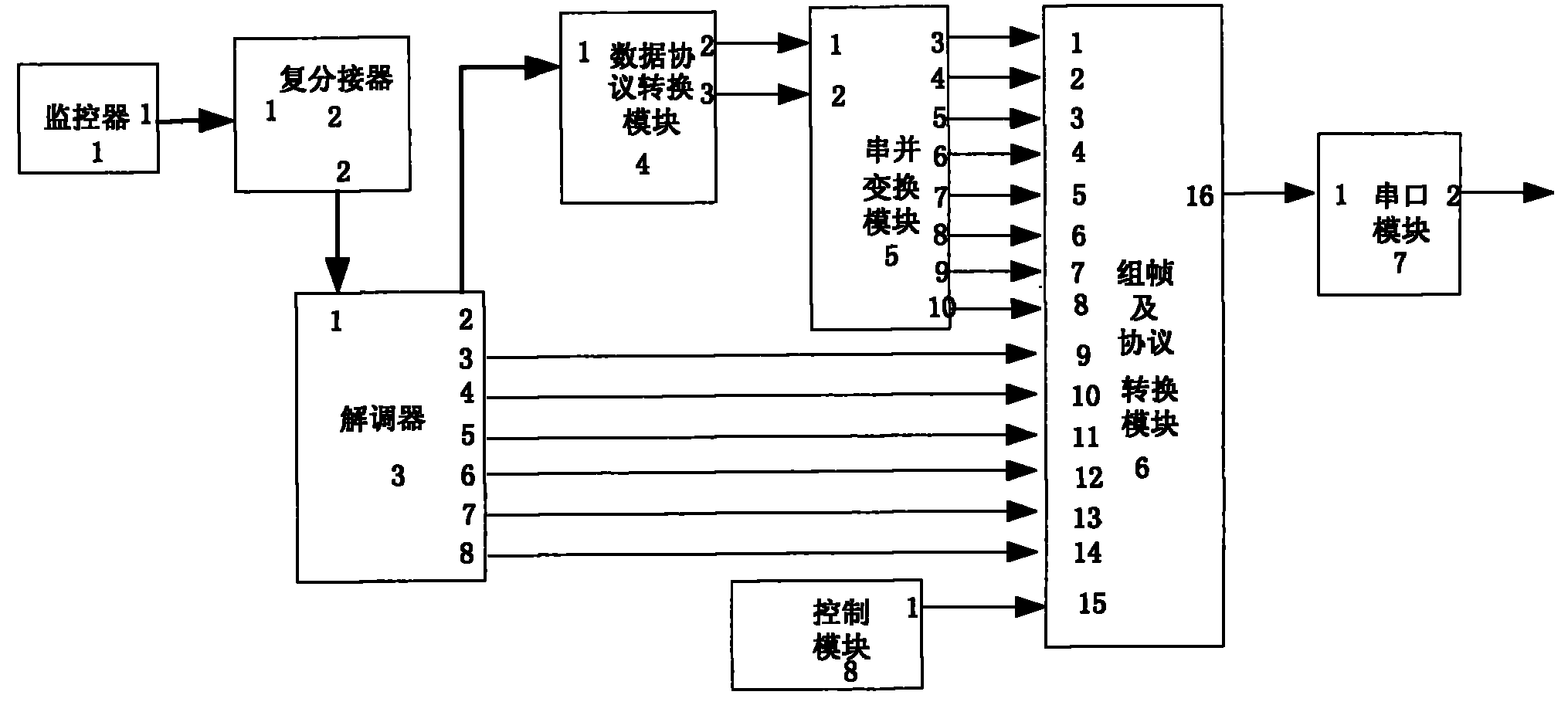
它包括监控器1、复分接器2、解调器3、数据协议转换模块4、串并变换模块5、组帧及协议转换模块6、串口输出模块7和控制模块8,还包括组帧及协议转换模块6;其中监控器1的出端口1与复分接器2入端口1相连,将监控器采集到的两端通信设备的GPS信息和接收电平信息传送给复分接器2;复分接器2的出端口2与解调器3的入端口1相连,复分接器2将计算得出的数据传输量、误码数、帧失步信号和通信距离信息加入到监控器传送的数据信息中,合并成一路数据流送给解调器3;解调器3的出端口2与数据协议转换模块4的入端口1相连,在数据协议转换模块4中将复分接器2送来的带有协议的信息转换为可用数据;解调器3的出端口3、4、5、6、7、8分别与组帧及协议转换模块6的入端口9、10、11、12、13、14相连,分别将解调器3采集到的两路分集信号频谱、两路信噪比、一路传输速率和一路解调后眼图送给组帧及协议转换模块6;数据协议转换模块4的出端口2、3分别与串并变换模块5的入端口1、2相连,分别将使能和串行的数据送入串并变换模块进行串并变换;串并变换模块5的出端口3、4、5、6、7、8、9、10分别与组帧及协议转换模块6的入端口1、2、3、4、5、6、7、8相连,分别将并行的两端GPS信息、两路接收电平、一路数据传输量、一路误码数、一路帧失步信号和一路通信距离数据送入组帧及协议转换模块6;组帧及协议转换模块6的入端口15与控制模块8的出端口1相连,得到组帧时所需的控制信号,组帧及协议转换模块6的出端口16与串口输出模块7的入端口1相连,组帧及协议转换模块6将入端口1至15输入的并行信号变换为串行信号,再将数据转换为符合串口协议的形式,输出给串口输出模块7;输出模块7的出端口2将带有串口协议的数据信息输出。It includes a monitor 1, a multiplexer 2, a demodulator 3, a data protocol conversion module 4, a serial-to-parallel conversion module 5, a framing and protocol conversion module 6, a serial port output module 7 and a control module 8, and also includes a framing And protocol conversion module 6; wherein the output port 1 of monitor 1 is connected with input port 1 of multiple tap 2, and the GPS information and receiving level information of the communication devices at both ends collected by the monitor are sent to multiple tap 2 ; The output port 2 of the multi-demultiplexer 2 is connected with the input port 1 of the demodulator 3, and the multi-demultiplexer 2 adds the calculated data transmission volume, bit error number, frame out-of-sync signal and communication distance information to the monitoring In the data information transmitted by the device, it is combined into a data stream and sent to the demodulator 3; the output port 2 of the demodulator 3 is connected with the input port 1 of the data protocol conversion module 4, and the multiple tap is connected in the data protocol conversion module 4. The information with the protocol sent by the device 2 is converted into usable data; the output ports 3, 4, 5, 6, 7, and 8 of the demodulator 3 are respectively connected with the input ports 9, 10, and 11 of the framing and protocol conversion module 6 . The output ports 2 and 3 of the protocol conversion module 4 are connected to the input ports 1 and 2 of the serial-to-parallel conversion module 5 respectively, and the enabling and serial data are sent into the serial-to-parallel conversion module for serial-to-parallel conversion respectively; the serial-to-parallel conversion module 5 The outgoing ports 3, 4, 5, 6, 7, 8, 9, and 10 are respectively connected to the incoming ports 1, 2, 3, 4, 5, 6, 7, and 8 of the framing and protocol conversion module 6, and are connected in parallel respectively. The GPS information at both ends, the receiving level of two channels, the data transmission volume of one channel, the bit error number of one channel, the frame out-of-sync signal of one channel and the communication distance data of one channel are sent to the framing and protocol conversion module 6; the framing and protocol conversion module 6 The input port 15 is connected to the output port 1 of the control module 8 to obtain the control signal required for framing, and the output port 16 of the framing and protocol conversion module 6 is connected to the input port 1 of the serial port output module 7 for framing and protocol conversion Module 6 converts the parallel signals input by the input ports 1 to 15 into serial signals, and then converts the data into a form conforming to the serial port protocol, and outputs it to the serial port output module 7; the output port 2 of the output module 7 will carry the data of the serial port protocol Information output.

所述的组帧及协议转换模块6包括并串单元60、写控制单元61、读控制及组帧单元62、双口RAM单元63、改换串口协议单元64;其中并串单元60的入端口1至8分别与串并变换模块5的出端口3至10相连,接并串单元60的输入端口9至14脚分别与解调器3的出端口3~8相连,接并串单元60的入端口15与控制模块8的出端口1脚相连,将各种并行通信链路状态信息在控制信号下转换成串行数据流;写控制模块61的入端口1与并串单元60的出端口16相连,接收有效数据,写控制单元61的入端口2与改换串口协议单元64的出端口6相连,作为写控制模块61的工作使能信号,写控制模块61的入端口3与控制模块8的出端口1脚相连,作为写控制模块61的清零信号,写控制模块61的出端口4分别与读控制及组帧单元62的入端口2和改换串口协议单元64的入端口3相连,作为读控制及组帧单元62和串口协议单元64的工作使能信号,写控制模块61的出端口5与双口RAM单元63的入端口1相连,将有效数据送入RAM中,写控制模块61的出端口6与双口RAM单元63的入端口2相连,作为RAM的写使能信号,写控制模块61的出端口7与双口RAM单元63的入端口3相连,作为RAM的写地址;读控制及组帧单元62的入端口1与双口RAM单元63的出端口6相连,将RAM读出的数据送入读控制及组帧单元62,读控制及组帧单元62的入端口3与改换串口协议单元64的出端口7相连,用来控制读控制及组帧单元62的读使能信号,读控制及组帧单元62的入端口4与控制模块8的出端口1相连,作为读控制及组帧单元62的清零信号,读控制及组帧单元62的出端口5与双口RAM单元63的入端口4相连,作为RAM的读使能信号,读控制及组帧单元62的出端口6与双口RAM单元63的入端口5相连,作为RAM的读地址,读控制及组帧单元62的出端口7和8分别与改换串口协议单元64的入端口1和2相连,将带有协议的单比特数据流和数据流使能分别送入串口协议单元64进行数据的串口协议转换;改换串口协议单元64的入端口4与控制模块8的出端口1相连,作为改换串口协议单元64的清零信号,改换串口协议单元64的出端口5与串口输出模块7的入口端1脚相连,将带有串口协议的数据信息输出。Described framing and protocol conversion module 6 includes a parallel unit 60, a write control unit 61, a read control and framing unit 62, a dual-port RAM unit 63, and a serial port protocol unit 64; wherein the input port 1 of the parallel unit 60 Pins 8 to 8 are respectively connected to the output ports 3 to 10 of the serial-to-parallel conversion module 5, and pins 9 to 14 of the input ports connected to the parallel-serial unit 60 are respectively connected to the output ports 3-8 of the demodulator 3, and connected to the input ports of the parallel-serial unit 60. Port 15 is connected to pin 1 of the output port of the control module 8, and various parallel communication link state information is converted into a serial data stream under the control signal; the input port 1 of the write control module 61 and the output port 16 of the parallel-serial unit 60 Connect to receive valid data, the input port 2 of the write control unit 61 is connected to the output port 6 of the serial port protocol unit 64, as the work enable signal of the write control module 61, the input port 3 of the write control module 61 is connected to the output port 6 of the control module 8 Out port 1 pin is connected, as the clearing signal of write control module 61, the outlet port 4 of write control module 61 is connected with read control and the input port 2 of framing unit 62 and the input port 3 of changing serial port protocol unit 64 respectively, as Read control and the work enabling signal of framing unit 62 and serial port protocol unit 64, the output port 5 of write control module 61 is connected with the input port 1 of dual-port RAM unit 63, valid data is sent in the RAM, write control module 61 The output port 6 of the output port 6 is connected with the input port 2 of the dual-port RAM unit 63 as the write enable signal of the RAM, and the output port 7 of the write control module 61 is connected with the input port 3 of the dual-port RAM unit 63 as the write address of the RAM; The input port 1 of the read control and framing unit 62 is connected with the output port 6 of the dual-port RAM unit 63, and the data read from the RAM is sent to the read control and framing unit 62, and the input port 3 of the read control and framing unit 62 Connect with the outlet port 7 of the serial port protocol unit 64 for controlling the read enable signal of the read control and framing unit 62, the read control and the inlet port 4 of the framing unit 62 are connected with the outlet port 1 of the control module 8 as The clear signal of read control and framing unit 62, the output port 5 of read control and framing unit 62 is connected with the input port 4 of dual-port RAM unit 63, as the read enable signal of RAM, read control and framing unit 62 The outgoing port 6 of the dual-port RAM unit 63 is connected to the incoming port 5, as the read address of the RAM, the reading control and the outgoing port 7 and 8 of the framing unit 62 are respectively connected to the incoming ports 1 and 2 of the serial port protocol unit 64, The single-bit data stream with agreement and the data stream can be sent into serial port protocol unit 64 to carry out the serial port agreement conversion of data respectively; The clearing signal of the protocol unit 64 changes the output port 5 of the serial port protocol unit 64 to be connected to the input port 1 pin of the serial port output module 7, and outputs the data information with the serial port protocol.

本发明相比背景技术具有如下优点:Compared with background technology, the present invention has the following advantages:

1.本发明采用特殊协议,将采集到的各工作模块的测试数据通过串口方式发送到PC,具有准确性。1. The present invention uses a special protocol to send the collected test data of each working module to the PC through the serial port, which is accurate.

2.本发明可监测机载设备诸多信息,例如;两路分集信号频谱、SNR估计值、接收电平,均衡后眼图,传输速率,误码率和两端通信设备所处GPS方位,通信距离等,具有信息容量大的特点。2. The present invention can monitor many information of airborne equipment, such as: two-way diversity signal spectrum, SNR estimated value, receiving level, eye diagram after equalization, transmission rate, bit error rate and GPS orientation of communication equipment at both ends, communication It has the characteristics of large information capacity.

3.本发明采用高速晶振驱动,从信号采集到送PC用时很短,每秒钟更新数据一次,具有实时性。3. The present invention is driven by a high-speed crystal oscillator, and the time from signal collection to sending to the PC is very short, and the data is updated once per second, which is real-time.

4.本发明依靠设备自身的电路和程序,不需额外增加电路,具有较低的系统开销,适用于轻型化机载设备。4. The present invention relies on the circuit and program of the device itself, does not need additional circuits, has low system overhead, and is suitable for lightweight airborne devices.

5.本发明电路部件采用一片FPGA器件制作,可灵活地修改、配置工作参数,具有集成化程度高、体积小、重量轻、性能稳定可靠的优点,采用全数字方法实现,使设备的结构大大简化,成本显著降低。5. The circuit components of the present invention are made of a piece of FPGA device, which can flexibly modify and configure working parameters. It has the advantages of high integration, small size, light weight, and stable and reliable performance. It is realized by an all-digital method, which greatly improves the structure of the equipment Simplified and significantly reduced costs.

附图说明Description of drawings

图1是本发明电原理方框图。Fig. 1 is a block diagram of the electrical principle of the present invention.

图2是本发明组帧及协议转换模块6实施例的电原理图。FIG. 2 is an electrical schematic diagram of an embodiment of the framing and protocol conversion module 6 of the present invention.

具体实施方式Detailed ways

参照图1至图2,本发明由监控器1、复分接器、解调器3、数据协议转换模块4、串并变换模块5、组帧及协议转换模块6、串口输出模块7、控制模块8组成。图1是本发明的电原理方框图,实施例按图1连接线路。With reference to Fig. 1 to Fig. 2, the present invention consists of monitor 1, multiplexer, demodulator 3, data protocol conversion module 4, serial-to-parallel conversion module 5, framing and protocol conversion module 6, serial port output module 7, control It consists of 8 modules. Fig. 1 is the electric principle block diagram of the present invention, and embodiment connects circuit according to Fig. 1.

本发明中的监控器1对通信设备所处GPS方位,两路分集接收电平信号进行采集,按某种协议方式处理数据,将信息数据变换成单比特数据流,再通过母板连线传送给复分接器2。The monitor 1 in the present invention collects the GPS azimuth and two-way diversity receiving level signal of the communication equipment, processes the data according to a certain protocol, converts the information data into a single-bit data stream, and then transmits it through the motherboard connection to multiplexer 2.

本发明中的复分接器2首先对数据传输量、误码个数、帧失步信号、通信距离信息进行采集,还要将监控器传送来的数据还原,再将监控器1和复分接器2的采集数据合并成一路,按某种协议送给解调器3。The multiple demultiplexer 2 in the present invention first collects the data transmission amount, the number of bit errors, the frame out-of-sync signal, and the communication distance information, and also restores the data transmitted by the monitor, and then divides the monitor 1 and The data collected by the receiver 2 are combined into one channel and sent to the demodulator 3 according to a certain protocol.

本发明中的解调器3对两路分集信号的信噪比进行计算,得出SNR估计值,然后采集两路分集信号SNR估计值、两路分集信号频谱、均衡后眼图数据、传输速率信息。The demodulator 3 in the present invention calculates the signal-to-noise ratio of the two-way diversity signals to obtain an estimated SNR value, and then collects the SNR estimated value of the two-way diversity signals, the frequency spectrum of the two-way diversity signals, the eye diagram data after equalization, and the transmission rate information.

本发明中的数据协议转换模块4,将复分接器2按某种协议送给解调器3的单比特数据进行协议转换,得到串行的多比特有效数据信息。The data protocol conversion module 4 in the present invention performs protocol conversion on the single-bit data sent by the multiplexer 2 to the demodulator 3 according to a certain protocol, and obtains serial multi-bit effective data information.

本发明中的串并变换模块5,将模块4输出的串行有效数据信息转换为并行数据。The serial-to-parallel conversion module 5 in the present invention converts the serial effective data information output by the module 4 into parallel data.

本发明中的组帧及协议转换模块6,将上述模块采集到的各种信息(两端通信设备所处GPS方位、两路分集接收电平信号、数据传输量、误码个数、帧失步信号、通信距离两路分集信号SNR估计值、两路分集信号频谱、均衡后眼图数据、传输速率信息)按某种协议处理,存入RAM中,按大约每秒一次的更新速率从RAM读出,再转换成符合串口协议的115.2kHz的数据流,输出数据。The framing and protocol conversion module 6 in the present invention collects various information (the GPS position of the communication equipment at both ends, the two-way diversity receiving level signal, the amount of data transmission, the number of error codes, and the number of frame errors) collected by the above modules. Step signal, communication distance two-way diversity signal SNR estimated value, two-way diversity signal spectrum, eye diagram data after equalization, transmission rate information) are processed according to a certain protocol, stored in RAM, and updated from RAM at a rate of about once per second Read out, and then convert it into a 115.2kHz data stream that conforms to the serial port protocol, and output the data.

本发明中的串口输出模块7,将符合串口协议的115.2kHz的数据流输出。The serial port output module 7 in the present invention outputs the 115.2kHz data stream conforming to the serial port protocol.

本发明中的控制模块8,产生一秒钟一次的使能信号,用于控制组帧及协议转换模块6中的工作时序。The control module 8 in the present invention generates an enable signal once a second for controlling the working sequence in the framing and protocol conversion module 6 .

本发明简要工作原理如下:Brief operating principle of the present invention is as follows:

监控器1收集从GPS传来的设备GPS方位信号,从射频单元传来的接收电平信号,将信息数据变换成按某种协议方式处理的单比特数据流,送给复分接器2。在复分接器2中,首先将监控器传送来的数据还原,其次统计自身的每秒钟的数据传输量、误码个数、帧失步次数,并通过GPS方位信号计算出通信距离,最后将监控器1和复分接器2要上报的数据合并成一路,并变换成单比特数据流送给解调器3。解调器3对两路分集信号的信噪比进行计算,得出SNR估计值,然后将两路SNR估计值、两路分集信号频谱、一路后眼图数据、一路传输速率信息并行的送入组帧及协议转换模块6,同时在解调器3中,将复分接器2要上报来的数据转发给协议转换模块4。在协议转换模块4中,将复分接器2上报来的单比特数据,转换成串行的多比特有效数据信息,送入串并变换模块5,再将串行数据转换为多路并行数据,同解调器的上报数据一起送入组帧及协议转换模块6。在组帧及协议转换模块6中将上述各种并行数据,送入并串单元60,按某种协议转换成串行数据,送入写控制单元61。在写控制单元61中,根据控制模块8送来的每秒清零信号和改换串口协议单元64送来的写允许信号,产生双口RAM单元63的写使能信号和写地址信号,并使上报数据与写地址对应,同时还产生读控制及组帧单元62的读允许信号。读控制及组帧单元62在根据读允许信号和模块8送来的每秒清零信号,产生双口RAM单元63的读使能信号和读地址信号。双口RAM单元63在上述信号的控制下,将协议数据从RAM读出,并送到读控制及组帧单元62。读控制及组帧单元62在由改换串口协议单元64产生的读使能信号控制下,使多比特的上报数据转换成单比特数据流,并产生单比特数据流使能信号,同时送给改换串口协议单元64。串口协议单元64在模块8送来的每秒清零信号和读控制及组帧单元62送来得读允许信号下,将上报的单比特数据流,转换成符合串口协议的的数据流,再通过串口输出模块7输出。The monitor 1 collects the GPS orientation signal of the device from the GPS and the receiving level signal from the radio frequency unit, converts the information data into a single-bit data stream processed according to a certain protocol, and sends it to the multiplexer 2 . In the multiplexer 2, first restore the data transmitted by the monitor, and then count its own data transmission volume per second, the number of bit errors, and the number of frame out-of-sync times, and calculate the communication distance through the GPS position signal, Finally, the data to be reported by the monitor 1 and the demultiplexer 2 are combined into one, and converted into a single-bit data stream and sent to the demodulator 3 . The demodulator 3 calculates the signal-to-noise ratio of the two channels of diversity signals to obtain an estimated SNR value, and then sends the two channels of SNR estimated values, the spectrum of the two channels of diversity signals, one channel of rear eye diagram data, and one channel of transmission rate information to the The framing and protocol conversion module 6 forwards the data to be reported by the multiplexer 2 to the protocol conversion module 4 in the demodulator 3 at the same time. In the protocol conversion module 4, the single-bit data reported by the multiplexer 2 is converted into serial multi-bit effective data information, and sent to the serial-to-parallel conversion module 5, and then the serial data is converted into multiple parallel data , sent to the framing and protocol conversion module 6 together with the reported data from the demodulator. In the framing and protocol conversion module 6 , the above-mentioned various parallel data are sent to the parallel-serial unit 60 , converted into serial data according to a certain protocol, and sent to the writing control unit 61 . In the write control unit 61, according to the reset signal per second sent by the control module 8 and the write permission signal sent by the serial port protocol unit 64, the write enable signal and the write address signal of the dual-port RAM unit 63 are generated, and the The reported data corresponds to the write address, and at the same time, a read permission signal for the read control and framing unit 62 is also generated. The read control and framing unit 62 generates a read enable signal and a read address signal for the dual-port RAM unit 63 according to the read enable signal and the reset signal per second sent by the module 8 . The dual-port RAM unit 63 reads the protocol data from the RAM under the control of the above signals, and sends it to the read control and framing unit 62 . The read control and framing unit 62 converts the multi-bit reported data into a single-bit data stream under the control of the read enable signal generated by the serial port protocol unit 64, and generates a single-bit data stream enable signal, which is sent to the converter at the same time. Serial port protocol unit 64. The serial port protocol unit 64 converts the reported single-bit data stream into a data stream conforming to the serial port protocol under the reset signal per second sent by the module 8 and the read permission signal sent by the read control and framing unit 62, and then passes Serial port output module 7 output.

本发明安装结构如下:The installation structure of the present invention is as follows:

把图1中监控器1、复分接器、解调器3,三块电路板安装在一个长、宽、高为433×256×194mm的机箱内,三块电路板之间的联线通过母板实现;数据协议转换模块4、串并变换模块5、组帧及协议转换模块6、、控制模块8,5个软件模块都在解调器3上的PFGA中实现;串口输出模块7在复分接2电路板上,串口数据最后通过机箱前面板接口输出;机箱内装有电源板,组装成本发明。Install the monitor 1, multiple splitter, demodulator 3 and three circuit boards in Figure 1 in a case whose length, width and height are 433×256×194mm, and the connection lines between the three circuit boards pass through Motherboard realizes; data protocol conversion module 4, serial-to-parallel conversion module 5, framing and protocol conversion module 6, control module 8, and 5 software modules are all realized in the PFGA on the demodulator 3; the serial port output module 7 is in On the multiple tap 2 circuit board, the serial port data is finally output through the interface on the front panel of the case; a power board is installed in the case, and the assembly cost is the invention.

Claims (2)

1. airborne communication link data statistic device, comprise watch-dog (1), multiplexer-demultiplexer (2), demodulator (3), data protocol modular converter (4), serial to parallel conversion module (5), serial ports output module (7) and control module (8), it is characterized in that: also comprise framing and protocol conversion module (6); Wherein the outbound port 1 of watch-dog (1) links to each other with multiplexer-demultiplexer (2) inbound port 1, and the GPS information and the incoming level information of the communication equipment present position, two ends that watch-dog is collected send multiplexer-demultiplexer (2) to; The outbound port 2 of multiplexer-demultiplexer (2) links to each other with the inbound port 1 of demodulator (3), multiplexer-demultiplexer (2) joins volume of transmitted data, number of bit errors, OOF signal and the communication distance information that calculates in the data message of watch-dog transmission, is merged into a circuit-switched data stream and gives demodulator (3); The outbound port 2 of demodulator (3) links to each other with the inbound port 1 of data protocol modular converter (4), and the information translation of in data protocol modular converter (4) multiplexer-demultiplexer (2) being sent here that has agreement is a data available; The outbound port 3,4,5,6,7,8 of demodulator (3) links to each other with the inbound port 9,10,11,12,13,14 of framing and protocol conversion module (6) respectively, and eye pattern is given framing and protocol conversion module (6) after two-way diversity signal frequency spectrum, two-way signal to noise ratio, one tunnel transmission rate and one tunnel demodulation that demodulator (3) is collected respectively; The outbound port 2,3 of data protocol modular converter (4) links to each other with the inbound port 1,2 of serial to parallel conversion module (5) respectively, will enable to send into the serial to parallel conversion module with the data of serial respectively and carry out serial to parallel conversion; The outbound port 3,4,5,6,7,8,9,10 of serial to parallel conversion module (5) links to each other with the inbound port 1,2,3,4,5,6,7,8 of framing and protocol conversion module (6) respectively, respectively parallel two ends GPS information, two-way incoming level, a circuit-switched data transmission quantity, one tunnel number of bit errors, one road OOF signal and one road communication distance data is sent into framing and protocol conversion module (6); The inbound port 15 of framing and protocol conversion module (6) links to each other with the outbound port 1 of control module (8), required control signal when obtaining framing; The outbound port 16 of framing and protocol conversion module (6) links to each other with the inbound port 1 of serial ports output module (7), framing and protocol conversion module (6) are transformed to serial signal with the parallel signal of inbound port 1 to 15 input, again data are converted to the form that meets serial port protocol, export to serial ports output module (7); The outbound port 2 of output module (7) will have the data message output of serial port protocol.
2. according to the described airborne communication link data of claim 1 statistic device, it is characterized in that: described framing and protocol conversion module (6) comprise and string location (60), write control unit (61), read control and framing unit (62), dual port RAM unit (63) and change serial port protocol unit (64); Wherein also the inbound port 1 to 8 of string location (60) is connected with the outbound port 3 to 10 of serial to parallel conversion module (5) respectively, and input port 9 to 14 pin of string location (60) are connected with the outbound port 3~8 of demodulator (3) respectively, and the inbound port 15 of string location (60) links to each other with outbound port 1 pin of control module (8), converts various parallel communication link state informations to serial data stream under control signal; The inbound port 1 of writing control module (61) with and the outbound port 16 of string location (60) link to each other, be used to receive valid data, the inbound port 2 of writing control unit (61) links to each other with the outbound port 6 that changes serial port protocol unit (64), as the work enable signal of writing control module (61), the inbound port 3 of writing control module (61) links to each other with outbound port 1 pin of control module (8), as the reset signal of writing control module (61), the outbound port 4 of writing control module (61) links to each other with the inbound port 3 that changes serial port protocol unit (64) with the inbound port 2 of reading control and framing unit (62) respectively, as the work enable signal of reading control and framing unit (62) and serial port protocol unit (64), the outbound port 5 of writing control module (61) links to each other with the inbound port 1 of dual port RAM unit (63), valid data are sent among the RAM, the outbound port 6 of writing control module (61) links to each other with the inbound port 2 of dual port RAM unit (63), the enable signal of writing as RAM, the outbound port 7 of writing control module (61) links to each other with the inbound port 3 of dual port RAM unit (63), as the write address of RAM; The inbound port 1 of reading control and framing unit (62) links to each other with the outbound port 6 of dual port RAM unit (63), the data that RAM is read are sent into and are read control and framing unit (62), the inbound port 3 of reading control and framing unit (62) links to each other with the outbound port 7 that changes serial port protocol unit (64), be used for controlling the enable signal of reading of reading control and framing unit (62), the inbound port 4 of reading control and framing unit (62) links to each other with the outbound port 1 of control module (8), as the reset signal of reading control and framing unit (62), the outbound port 5 of reading control and framing unit (62) links to each other with the inbound port 4 of dual port RAM unit (63), the enable signal of reading as RAM, the outbound port 6 of reading control and framing unit (62) links to each other with the inbound port 5 of dual port RAM unit (63), the address of reading as RAM, the outbound port 7 of reading control and framing unit (62) links to each other with 2 with the inbound port 1 that changes serial port protocol unit (64) respectively with 8, and the single bit data stream and the data flow that will have agreement enable to send into respectively the serial port protocol conversion that serial port protocol unit (64) carries out data; The inbound port 4 that changes serial port protocol unit (64) links to each other with the outbound port 1 of control module (8), as the reset signal that changes serial port protocol unit (64), the outbound port 5 that changes serial port protocol unit (64) links to each other with arrival end 1 pin of serial ports output module (7), will have the data message output of serial port protocol.
CN 201010568916 2010-12-02 2010-12-02 Onboard communication chain data statistic device Expired - Fee Related CN102158366B (en)

Priority Applications (1)

Application Number Priority Date Filing Date Title
CN 201010568916 CN102158366B (en) 2010-12-02 2010-12-02 Onboard communication chain data statistic device

Applications Claiming Priority (1)

Application Number Priority Date Filing Date Title
CN 201010568916 CN102158366B (en) 2010-12-02 2010-12-02 Onboard communication chain data statistic device

Publications (2)

Publication Number Publication Date
CN102158366A true CN102158366A (en) 2011-08-17
CN102158366B CN102158366B (en) 2013-07-03

Family

ID=44439567

Family Applications (1)

Application Number Title Priority Date Filing Date
CN 201010568916 Expired - Fee Related CN102158366B (en) 2010-12-02 2010-12-02 Onboard communication chain data statistic device

Country Status (1)

Country Link
CN (1) CN102158366B (en)

Cited By (1)

* Cited by examiner, † Cited by third party
Publication number Priority date Publication date Assignee Title
CN109361476A (en) * 2018-12-18 2019-02-19 中国电子科技集团公司第五十四研究所 A portable microwave line-of-sight measuring device

Citations (3)

* Cited by examiner, † Cited by third party
Publication number Priority date Publication date Assignee Title
CN101296214A (en) * 2008-06-25 2008-10-29 中国电子科技集团公司第五十四研究所 Time Orthogonal Frequency Division Multiplexing Modem
CN101359993A (en) * 2008-08-20 2009-02-04 中国电子科技集团公司第五十四研究所 High Speed Burst Modem
CN201467137U (en) * 2009-09-07 2010-05-12 中国电子科技集团公司第五十四研究所 An online channel test terminal

Patent Citations (3)

* Cited by examiner, † Cited by third party
Publication number Priority date Publication date Assignee Title
CN101296214A (en) * 2008-06-25 2008-10-29 中国电子科技集团公司第五十四研究所 Time Orthogonal Frequency Division Multiplexing Modem
CN101359993A (en) * 2008-08-20 2009-02-04 中国电子科技集团公司第五十四研究所 High Speed Burst Modem
CN201467137U (en) * 2009-09-07 2010-05-12 中国电子科技集团公司第五十四研究所 An online channel test terminal

Cited By (2)

* Cited by examiner, † Cited by third party
Publication number Priority date Publication date Assignee Title
CN109361476A (en) * 2018-12-18 2019-02-19 中国电子科技集团公司第五十四研究所 A portable microwave line-of-sight measuring device
CN109361476B (en) * 2018-12-18 2021-07-06 中国电子科技集团公司第五十四研究所 A portable microwave line-of-sight measuring device

Also Published As

Publication number Publication date
CN102158366B (en) 2013-07-03

Similar Documents

Publication Publication Date Title
US8660424B2 (en) Scalable high speed gigabit active bundle link and tester
CN102413018B (en) FPGA (field programmable gate array) based software-hardware coordinated network test system and method
CN107167174B (en) Distributed type minisize data collecting system
CN103678212B (en) Based on the general-purpose interface detection device of VPX framework
CN104168162B (en) A kind of software-hardware synergism realizes the traffic generator for interchanger validation test
CN102438010A (en) Method and arrangement for streaming data profiling
CN115061082B (en) Signal processing method and device for interferometer direction finding narrow-band receiver
CN106548613A (en) For the region microwave link networking signal pickup assembly and method of Rainfall estimation
CN204761602U (en) Machine carries general video acquisition system
CN102158366B (en) Onboard communication chain data statistic device
CN103036707B (en) Portable IPTV service service quality diagnostic device and diagnostic method
CN201467137U (en) An online channel test terminal
CN101394197A (en) A baseband data transmission method and equipment for a CDMA distributed base station system
WO2015138244A1 (en) Systems and methods for detecting errors and recording actions on a bus
CN201372742Y (en) A wireless information acquisition system of well drilling field
CN114006850B (en) Portable avionics bus test system and internal data transmission method
CN208128267U (en) A kind of TTE router performance detection system
CN110880959A (en) Hardware processing platform for realizing large-scale multi-channel full interconnection based on FPGA array
CN208015747U (en) Non-intervention type multiprotocol network data acquisition device
CN106844127A (en) A kind of highly reliable modular testing emulation platform
CN101577598A (en) Multiple signal multiplexing and demultiplexing methods, devices and systems
CN103197344B (en) For the command transfer of relay-type step by step method, the transmission board of offshore seismic exploration towing cable
CN1140976C (en) SS7 Signal Analyzer
CN103051918A (en) Portable front-end video detector and detection method thereof
CN106059695A (en) Meteoric trail communication based motorized command system training support device

Legal Events

Date Code Title Description
C06 Publication
PB01 Publication
C10 Entry into substantive examination
SE01 Entry into force of request for substantive examination
C14 Grant of patent or utility model
GR01 Patent grant
CF01 Termination of patent right due to non-payment of annual fee

Granted publication date: 20130703

CF01 Termination of patent right due to non-payment of annual fee